EP0171614A2 - Coupleur pour connecter des fibres optiques - Google Patents
Coupleur pour connecter des fibres optiques Download PDFInfo
- Publication number
- EP0171614A2 EP0171614A2 EP85108725A EP85108725A EP0171614A2 EP 0171614 A2 EP0171614 A2 EP 0171614A2 EP 85108725 A EP85108725 A EP 85108725A EP 85108725 A EP85108725 A EP 85108725A EP 0171614 A2 EP0171614 A2 EP 0171614A2
- Authority
- EP
- European Patent Office
- Prior art keywords
- sleeve
- notch
- optical fibers
- passage
- diameter
- Prior art date
- Legal status (The legal status is an assumption and is not a legal conclusion. Google has not performed a legal analysis and makes no representation as to the accuracy of the status listed.)
- Granted
Links
Images

Classifications
-
- G—PHYSICS
- G02—OPTICS
- G02B—OPTICAL ELEMENTS, SYSTEMS OR APPARATUS
- G02B6/00—Light guides; Structural details of arrangements comprising light guides and other optical elements, e.g. couplings
- G02B6/24—Coupling light guides
-
- G—PHYSICS
- G02—OPTICS
- G02B—OPTICAL ELEMENTS, SYSTEMS OR APPARATUS
- G02B6/00—Light guides; Structural details of arrangements comprising light guides and other optical elements, e.g. couplings
- G02B6/24—Coupling light guides
- G02B6/36—Mechanical coupling means
- G02B6/38—Mechanical coupling means having fibre to fibre mating means
- G02B6/3801—Permanent connections, i.e. wherein fibres are kept aligned by mechanical means
- G02B6/3803—Adjustment or alignment devices for alignment prior to splicing
Definitions
- the present invention relates to optical fiber connecting couplers for interconnecting optical fibers, and more particularly to those couplers in which optical fibers, exposed by removing end portion coatings, are inserted into optical fiber insertion holes from opposite ends, the insertion holes having inner diameters slightly large than the fiber diameters.
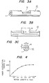
- FIGURE lA is a perspective view and FIGURE 1B is a longitudinal cross-sectional view of a conventional optical fiber connecting sleeve 1.
- Sleeve 1 is made of ceramics and has a length of 10 mm.
- Sleeve 1 is provided with an optical fiber insertion hole 2 having an internal diameter of 0.128mm for an optical fiber diameter of 0.125 mm.
- Sleeve 1 has also a hole 3 at its center portion in which matching oil may be inserted.
- optical fibers 5 are exposed by removing the end portion coatings of the respective coated optical fibers 4. Then the respective ends of optical fibers 5 are cut to be mirror faces and the respective optical fibers 5 are inserted into optical insertion hole 2 of sleeve 1 from opposite ends thereof. A matching agent is then injected into hole 3 to prevent Fresnel reflection.
- a first problem with sleeve-1 is that it is impossible to make visual confirmation as to whether the respective end faces of optical fibers 5 about against each other in sleeve 1. Instead proper abutment can be determined based only on feel. Therefore, in good cases, the loss in the connection portion is 0.1 dB or less, but in bad cases, the loss often is 3 dB or more.
- a second problem is that matching agent may flow out from hole 3.
- An experiment has shown that an initial loss of 0.1 dB increased to 0.4 dB when vibrations having a frequency of 10 Hz and an amplitude of +5 mm were applied for 200 hours. When matching agent was added again, the loss returned to 0.1 dB.
- An object of the present invention is to provide an improved optical fiber connecting coupler in which the aforementioned problems are eliminated. That is, the coupler of the present invention connects optical fibers with little loss which is maintained for an extended period.
- a sleeve for connecting optical fibers has a cylindrical shape and an axial passage therethrough.
- the passage has a diameter slightly larger than the diameter of the optical fibers being connected.
- the sleeve defines a notch in its outer periphery of its central portion. The notch extends radially inward to expose the passage -through the sleeve.
- the width, in a direction perpendicular t6 the longitudinal axis of the sleeve, across the opening into the passage provided by the notch, is less than the diameter of the optical fibers.
- the notch is sufficiently large to permit visual inspection of optical fibers in the passage.
- the length of the notch in the longitudinal direction may advantageously be at least 5 times the outer diameter of the optical fibers. It is also advantageous that an adhesive agent be disposed in the notch, the adhesive agent being selected to perform a matching function between the optical fibers.
- the sleeve may be positioned in a housing to form a coupler.
- the housing seals the notch and may include a portion extending into the notch.
- the housing may have two halves with a spring sleeve holding the halves together.
- One of the halves may have pressure sensitive adhesive on an inner peripheral surface at opposite ends to cause the optical fibers to stick to the housing.
- One of the housing halves may include a groove for guiding the optical fibers.
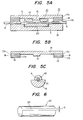
- a connecting sleeve 10 is generally cylindrical and hollow.
- a notch 12 is provided at a central portion of sleeve 10 in its outer periphery.
- notch 12 has a depth d sufficient to expose the passage within sleeve 10.
- the width, in a direction perpendicular to the longitudinal axis of sleeve 10, across the opening into the passage within sleeve 10, is defined as a. Width a is smaller than the outer diameter of an optical fiber.
- FIGURE 4 illustrates the relationship between the force for extracting the optical fiber from sleeve 10 and the axial length L of notch 12 when adhesive is applied to optical fibers 5 in notch 12 as will be described below.
- An extraction force of at least 500 g has been determined desirable to prevent separation of the optical fiber from sleeve 10. Therefore, the value of L should be equal to or larger than 0.6 mm so that the optical fiber is exposed by a length L five or more times the outer diameter of optical fiber 5 when the latter is 0.125 mm.
- FIGURE 5A illustrates connecting sleeve 10 in which optical fibers 5 have been connected.
- Sleeve 10 is accommodated in a housing having upper and lower parts 14 and 16. Where optical fibers 5 abut, an adhesive agent 20 is injected into sleeve 10 through notch 12 so as to fix the position of optical fibers 5.
- Upper housing part 14 is provided at its center portion with a seal portion 15 which extends into notch 12 to thereby prevent adhesive agent 20 from flowing out.
- the inner peripheral surfaces at opposite ends of upper housing part 14 are provided with pressure sensitive adhesive agent layers so that coated portions 4 of the respective optical fibers are fixed by these pressure sensitive adhesive agent layers when the upper and lower housing parts 14 and 16 are assembled.
- each of the inner peripheral surfaces at opposite ends of upper housing part 14 is provided with a first adhesive agent layer 17a, a foaming agent layer 18, a second adhesive agent layer 17b and a separator 19. In use, separator 19 is removed so that second adhesive layer 7b sticks to coated optical fiber 4 ⁇ .
- Lower housing part 16 has a guide groove 21 for holding each of coated optical fibers 4 as shown in FIGURE 5C.
- a spring sleeve 22 (see FIGURE 6) having a slit 23 surrounds housing parts 14 and 16 to fix and protect them.
- spring sleeve 22 can be easily positioned around housing parts 14 and 16 even after the housing parts 14 and 16 have been assembled.
- a connecting sleeve 10 as shown in FIGURES 3A - 3C was produced made of ceramics.
- SleeVE 10 had a length of 10 mm, an outer diameter of 2 mm, and an optical fiber insertion hole of 0.128 mm.
- notch 12 was formed having a length (L) of 2 mm and a depth d such that the exposed portion width a was 0.1 mm.
- Coated optical fibers 4 were connected using sleeve 10, with the diameter of each optical fiber 5 being 0.125 mm and the outer diameter of coated optical fiber 4 being 0.9 mm. The coating at the end portion of each coated optical fiber 4 was removed to expose optical fiber 5 at that portion, and the end portion was cut by an optical fiber cutter to obtain a mirror end face. Each optical fiber 5 was inserted into an optical fiber insertion hole of connecting sleeve 10. Since notch 12 had a length of 2 mm, the abutment between optical fibers 5 could be visually confirmed. The abutment could also be easily observed with a microscope of about 20 power magnification or a loupe or magnifying glass.
- An instant adhesive agent 20 of a cianoacrylate group was dropped through notch 12 to optical fibers 4 which were positioned in a manner as described above.
- adhesive agent 20 it is possible to prevent a Fresnel loss from occurring, to improve the loss to be 0.2 - 0.3 dB, and to fix optical fibers 5 to connecting sleeve 10.
- connecting sleeve 10 in which optical fibers 5 were connected, was positioned in a housing having upper and lower parts 14 and 16 as shown in FIGURES 5A - 5C.
- a four-layer pressure sensitive arrangement was provided composed of a first adhesive agent layer 17a, a foaming agent layer 18, a second adhesive agent layer 17b and a separator 19, as shown in FIGURE 5B. Separator 19 was removed and upper and lower housing parts 14 and 16 were pressed against each other so as to fix coated optical fibers 4.
- the thickness of the layers was selected to be about 1.3 mm.
- a material of an acrylic-group was used as the pressure sensitive adhesive agent, and a polyethylene foam material was used as the foam agent.
- a spring sleeve 22 having a slit 23 was attached on the outer periphery of the housing so that firm and stable fixing of the housing could be obtained. At that time, the outer diameter of the spring sleeve was about 4.5 mm.
- optical fiber connecting coupler of the present invention it is possible to perform positional adjustment of the gap between the end surfaces of optical fibers in the sleeve while visually observing them. At the same time a stable connection is provided exhibiting a loss not exceeding 1 dB, while having a low average loss of 0.23 dB. Also matching agent can be maintained in the sleeve for a long term by the use of an adhesive agent having a matching function.
- the sleeve connection can be protected by the use of the housing and the coated optical fibers of the optical fibers can be fixed with ease by the pressure sensitive adhesive agent so that a stable connection can be maintained.
- upper housing part 14 may be provided with reversely tapered pawls for the purpose of preventing opening.
Applications Claiming Priority (2)
| Application Number | Priority Date | Filing Date | Title |
|---|---|---|---|
| JP14666784A JPS6125109A (ja) | 1984-07-13 | 1984-07-13 | 光フアイバ接続用結合部材 |
| JP146667/84 | 1984-07-13 |
Publications (3)
| Publication Number | Publication Date |
|---|---|
| EP0171614A2 true EP0171614A2 (fr) | 1986-02-19 |
| EP0171614A3 EP0171614A3 (en) | 1988-01-20 |
| EP0171614B1 EP0171614B1 (fr) | 1991-05-29 |
Family
ID=15412892
Family Applications (1)
| Application Number | Title | Priority Date | Filing Date |
|---|---|---|---|
| EP85108725A Expired - Lifetime EP0171614B1 (fr) | 1984-07-13 | 1985-07-12 | Coupleur pour connecter des fibres optiques |
Country Status (4)
| Country | Link |
|---|---|
| EP (1) | EP0171614B1 (fr) |
| JP (1) | JPS6125109A (fr) |
| KR (1) | KR900005738B1 (fr) |
| DE (1) | DE3582975D1 (fr) |
Cited By (8)
| Publication number | Priority date | Publication date | Assignee | Title |
|---|---|---|---|---|
| FR2598819A1 (fr) * | 1986-05-14 | 1987-11-20 | Univ Limoges | Connecteur pour fibres optiques. |
| FR2607597A2 (fr) * | 1986-05-14 | 1988-06-03 | Univ Limoges | Connecteur pour fibres optiques |
| US4778242A (en) * | 1986-08-05 | 1988-10-18 | Ngk Insulators, Ltd. | Reinforcement for optical-fiber joint |
| EP0374939A2 (fr) * | 1988-12-23 | 1990-06-27 | Nec Corporation | Embout d'un connecteur optique et méthode pour l'assembler |
| EP0381766A1 (fr) * | 1988-07-27 | 1990-08-16 | NIPPON ELECTRIC GLASS COMPANY, Limited | Connecteur permanent de fibres optiques |
| EP0443409A1 (fr) * | 1990-02-21 | 1991-08-28 | Cimeo Precision Company, Limited | Manchon pour la connexion de guides de lumière |
| GB2263178A (en) * | 1992-01-13 | 1993-07-14 | Televerket | Splicing optical waveguides using solidifiable refractive index matching gel |
| EP2304484A1 (fr) * | 2008-07-10 | 2011-04-06 | ADC Telecommunications, INC. | Ensemble connecteur de fibres optiques raccordable sur site |
Families Citing this family (14)
| Publication number | Priority date | Publication date | Assignee | Title |
|---|---|---|---|---|
| JP2566961B2 (ja) * | 1987-06-10 | 1996-12-25 | 日本電気株式会社 | 光ファイバコネクタフェル−ル |
| JPH02256006A (ja) * | 1988-06-09 | 1990-10-16 | Tokyo Electric Power Co Inc:The | 多心光ファイバ一括接続部 |
| JPH01310312A (ja) * | 1988-06-09 | 1989-12-14 | Tokyo Electric Power Co Inc:The | 多心光ファイバ一括接続方法 |
| JPH01310310A (ja) * | 1988-06-09 | 1989-12-14 | Tokyo Electric Power Co Inc:The | 光ファイバの接続部 |
| JP2635699B2 (ja) * | 1988-07-19 | 1997-07-30 | 古河電気工業株式会社 | 光ファイバコネクタ |
| JPH0750219B2 (ja) * | 1988-10-21 | 1995-05-31 | 日本電気株式会社 | 光コネクタ端末構造 |
| JP2670334B2 (ja) * | 1989-01-30 | 1997-10-29 | 古河電気工業株式会社 | 光ファイバ組込台 |
| JP2670332B2 (ja) * | 1989-01-30 | 1997-10-29 | 古河電気工業株式会社 | 光ファイバ組込台 |
| JP2670333B2 (ja) * | 1989-01-30 | 1997-10-29 | 古河電気工業株式会社 | 光ファイバ組込台 |
| JPH0229608A (ja) * | 1989-05-31 | 1990-01-31 | Furukawa Electric Co Ltd:The | 光ファイバコネクタ |
| JP3362329B2 (ja) * | 1995-06-26 | 2003-01-07 | 住友電気工業株式会社 | 光ファイバ接続部材とその製造方法及び接続方法 |
| KR100493336B1 (ko) * | 2001-11-02 | 2005-06-02 | 엔티티 어드밴스드 테크놀로지 코포레이션 | 광섬유 접속 부재, 광섬유 접속 슬리브, 광섬유 접속 방법 및 광섬유 접속 장치 |
| JP4968122B2 (ja) * | 2008-03-10 | 2012-07-04 | 日立電線株式会社 | 光コネクタ |
| JP4968123B2 (ja) * | 2008-03-10 | 2012-07-04 | 日立電線株式会社 | 光コネクタ |
Citations (7)
| Publication number | Priority date | Publication date | Assignee | Title |
|---|---|---|---|---|
| DE7517996U (de) * | 1975-06-05 | 1975-09-25 | Siemens Ag | Spleissverbindungsanordnung fuer einzellichtwellenleiter |
| GB2008274A (en) * | 1977-11-14 | 1979-05-31 | Thomas & Betts Corp | Splicing Optical Fibres |
| EP0033408A1 (fr) * | 1980-01-30 | 1981-08-12 | BICC Public Limited Company | Procédé de jonction de fibres optiques et joint de fibres optiques |
| JPS56122004A (en) * | 1980-02-29 | 1981-09-25 | Canon Inc | Optical fiber connector |
| DE8212379U1 (de) * | 1982-04-29 | 1982-09-23 | Siemens AG, 1000 Berlin und 8000 München | Vorrichtung zum klebespleissen von lichtwellenleitfasern |
| JPS582814A (ja) * | 1981-06-29 | 1983-01-08 | Nippon Telegr & Teleph Corp <Ntt> | 光伝送用フアイバの接続方法 |
| GB2118322A (en) * | 1982-04-09 | 1983-10-26 | Western Electric Co | Low loss optical fiber splicing |
-
1984
- 1984-07-13 JP JP14666784A patent/JPS6125109A/ja active Pending
-
1985
- 1985-07-04 KR KR1019850004793A patent/KR900005738B1/ko not_active IP Right Cessation
- 1985-07-12 EP EP85108725A patent/EP0171614B1/fr not_active Expired - Lifetime
- 1985-07-12 DE DE8585108725T patent/DE3582975D1/de not_active Expired - Fee Related
Patent Citations (7)
| Publication number | Priority date | Publication date | Assignee | Title |
|---|---|---|---|---|
| DE7517996U (de) * | 1975-06-05 | 1975-09-25 | Siemens Ag | Spleissverbindungsanordnung fuer einzellichtwellenleiter |
| GB2008274A (en) * | 1977-11-14 | 1979-05-31 | Thomas & Betts Corp | Splicing Optical Fibres |
| EP0033408A1 (fr) * | 1980-01-30 | 1981-08-12 | BICC Public Limited Company | Procédé de jonction de fibres optiques et joint de fibres optiques |
| JPS56122004A (en) * | 1980-02-29 | 1981-09-25 | Canon Inc | Optical fiber connector |
| JPS582814A (ja) * | 1981-06-29 | 1983-01-08 | Nippon Telegr & Teleph Corp <Ntt> | 光伝送用フアイバの接続方法 |
| GB2118322A (en) * | 1982-04-09 | 1983-10-26 | Western Electric Co | Low loss optical fiber splicing |
| DE8212379U1 (de) * | 1982-04-29 | 1982-09-23 | Siemens AG, 1000 Berlin und 8000 München | Vorrichtung zum klebespleissen von lichtwellenleitfasern |
Non-Patent Citations (2)
| Title |
|---|
| PATENT ABSTRACTS OF JAPAN, vol. 5, no. 201 (P-94)[873], 19th December 1981; & JP-A-56 122 004 (HIROSHI HANADA) 25-09-1981 * |
| PATENT ABSTRACTS OF JAPAN, vol. 7, no. 73 (P-186)[1218], 25th March 1983; & JP-A-58 002 814 (NIPPON DENSHIN DENWA KOSHA) 08-01-1983 * |
Cited By (14)
| Publication number | Priority date | Publication date | Assignee | Title |
|---|---|---|---|---|
| FR2607597A2 (fr) * | 1986-05-14 | 1988-06-03 | Univ Limoges | Connecteur pour fibres optiques |
| FR2598819A1 (fr) * | 1986-05-14 | 1987-11-20 | Univ Limoges | Connecteur pour fibres optiques. |
| US4778242A (en) * | 1986-08-05 | 1988-10-18 | Ngk Insulators, Ltd. | Reinforcement for optical-fiber joint |
| EP0381766A4 (en) * | 1988-07-27 | 1991-11-27 | Nippon Electric Glass Company, Limited | Optical fiber permanent connector |
| EP0381766A1 (fr) * | 1988-07-27 | 1990-08-16 | NIPPON ELECTRIC GLASS COMPANY, Limited | Connecteur permanent de fibres optiques |
| EP0374939A2 (fr) * | 1988-12-23 | 1990-06-27 | Nec Corporation | Embout d'un connecteur optique et méthode pour l'assembler |
| EP0374939A3 (fr) * | 1988-12-23 | 1991-07-31 | Nec Corporation | Embout d'un connecteur optique et méthode pour l'assembler |
| EP0443409A1 (fr) * | 1990-02-21 | 1991-08-28 | Cimeo Precision Company, Limited | Manchon pour la connexion de guides de lumière |
| GB2263178A (en) * | 1992-01-13 | 1993-07-14 | Televerket | Splicing optical waveguides using solidifiable refractive index matching gel |
| US5347606A (en) * | 1992-01-13 | 1994-09-13 | Televerket | Method and an arrangement for splicing optical waveguides |
| GB2263178B (en) * | 1992-01-13 | 1994-11-23 | Televerket | Splicing optical waveguides using solidifiable silica gel |
| EP2304484A1 (fr) * | 2008-07-10 | 2011-04-06 | ADC Telecommunications, INC. | Ensemble connecteur de fibres optiques raccordable sur site |
| US10162113B2 (en) | 2008-07-10 | 2018-12-25 | Commscope Technologies Llc | Field terminable fiber optic connector assembly |
| US10481329B2 (en) | 2008-07-10 | 2019-11-19 | Commscope Technologies Llc | Field terminable fiber optic connector assembly |
Also Published As
| Publication number | Publication date |
|---|---|
| EP0171614A3 (en) | 1988-01-20 |
| DE3582975D1 (de) | 1991-07-04 |
| EP0171614B1 (fr) | 1991-05-29 |
| KR860001356A (ko) | 1986-02-26 |
| JPS6125109A (ja) | 1986-02-04 |
| KR900005738B1 (ko) | 1990-08-09 |
Similar Documents
| Publication | Publication Date | Title |
|---|---|---|
| EP0171614A2 (fr) | Coupleur pour connecter des fibres optiques | |
| US4553814A (en) | Detachable fiber optic connector assembly | |
| US5971626A (en) | Fiber optic connector and connector sleeve assembly | |
| US4693550A (en) | Crimp type fiber optic connector | |
| US5390269A (en) | Fiber optic connector with high resolution tunable fiber holder | |
| US4526438A (en) | Alignment sleeve for fiber optic connectors | |
| US4730892A (en) | Optical fiber mechanical splice | |
| US4812006A (en) | Fiber optic connector with colley retention | |
| EP0125398A1 (fr) | Connecteur de fibre-optique | |
| EP0418503A1 (fr) | Ensemble de connection à fibre optique | |
| EP0290188A2 (fr) | Connecteur à fibres optiques | |
| US5140661A (en) | Optical fiber terminus | |
| US5905835A (en) | Optical fiber multi-ribbon | |
| US4605281A (en) | Self-aligning fiber optic connector | |
| EP0061243B1 (fr) | Connecteur pour guide d'ondes optiques | |
| JP4030940B2 (ja) | 光コネクタ及び光コネクタボックス | |
| US4217029A (en) | Interlocking precision optical fiber connector or support | |
| US4166672A (en) | Optical fiber connector | |
| EP0911661B1 (fr) | Ferrule pour connecteur de fibres optiques | |
| US4383732A (en) | Fiber optic connector | |
| EP0421305A1 (fr) | Ensemble de connection à fibre optique | |
| US4676588A (en) | Fiber optic connector | |
| US4712864A (en) | Multi-channel fiber optic connector | |
| CA2137239A1 (fr) | Connecteur a fibres optiques | |
| CA1276491C (fr) | Dispositif de raccordement reciproque de fibres optiques |
Legal Events
| Date | Code | Title | Description |
|---|---|---|---|
| PUAI | Public reference made under article 153(3) epc to a published international application that has entered the european phase |
Free format text: ORIGINAL CODE: 0009012 |
|
| AK | Designated contracting states |
Designated state(s): DE FR GB IT NL SE |
|
| PUAL | Search report despatched |
Free format text: ORIGINAL CODE: 0009013 |
|
| AK | Designated contracting states |
Kind code of ref document: A3 Designated state(s): DE FR GB IT NL SE |
|
| 17P | Request for examination filed |
Effective date: 19880415 |
|
| 17Q | First examination report despatched |
Effective date: 19891214 |
|
| GRAA | (expected) grant |
Free format text: ORIGINAL CODE: 0009210 |
|
| AK | Designated contracting states |
Kind code of ref document: B1 Designated state(s): DE FR GB IT NL SE |
|
| ET | Fr: translation filed | ||
| REF | Corresponds to: |
Ref document number: 3582975 Country of ref document: DE Date of ref document: 19910704 |
|
| ITF | It: translation for a ep patent filed |
Owner name: MODIANO & ASSOCIATI S.R.L. |
|
| PLBE | No opposition filed within time limit |
Free format text: ORIGINAL CODE: 0009261 |
|
| STAA | Information on the status of an ep patent application or granted ep patent |
Free format text: STATUS: NO OPPOSITION FILED WITHIN TIME LIMIT |
|
| 26N | No opposition filed | ||
| EAL | Se: european patent in force in sweden |
Ref document number: 85108725.4 |
|
| PGFP | Annual fee paid to national office [announced via postgrant information from national office to epo] |
Ref country code: SE Payment date: 20000705 Year of fee payment: 16 |
|
| PGFP | Annual fee paid to national office [announced via postgrant information from national office to epo] |
Ref country code: DE Payment date: 20000710 Year of fee payment: 16 |
|
| PGFP | Annual fee paid to national office [announced via postgrant information from national office to epo] |
Ref country code: FR Payment date: 20000711 Year of fee payment: 16 |
|
| PGFP | Annual fee paid to national office [announced via postgrant information from national office to epo] |
Ref country code: GB Payment date: 20000713 Year of fee payment: 16 |
|
| PGFP | Annual fee paid to national office [announced via postgrant information from national office to epo] |
Ref country code: NL Payment date: 20000728 Year of fee payment: 16 |
|
| PG25 | Lapsed in a contracting state [announced via postgrant information from national office to epo] |
Ref country code: GB Free format text: LAPSE BECAUSE OF NON-PAYMENT OF DUE FEES Effective date: 20010712 |
|
| PG25 | Lapsed in a contracting state [announced via postgrant information from national office to epo] |
Ref country code: SE Free format text: LAPSE BECAUSE OF NON-PAYMENT OF DUE FEES Effective date: 20010713 |
|
| PG25 | Lapsed in a contracting state [announced via postgrant information from national office to epo] |
Ref country code: NL Free format text: LAPSE BECAUSE OF NON-PAYMENT OF DUE FEES Effective date: 20020201 |
|
| EUG | Se: european patent has lapsed |
Ref document number: 85108725.4 |
|
| GBPC | Gb: european patent ceased through non-payment of renewal fee |
Effective date: 20010712 |
|
| PG25 | Lapsed in a contracting state [announced via postgrant information from national office to epo] |
Ref country code: FR Free format text: LAPSE BECAUSE OF NON-PAYMENT OF DUE FEES Effective date: 20020329 |
|
| NLV4 | Nl: lapsed or anulled due to non-payment of the annual fee |
Effective date: 20020201 |
|
| PG25 | Lapsed in a contracting state [announced via postgrant information from national office to epo] |
Ref country code: DE Free format text: LAPSE BECAUSE OF NON-PAYMENT OF DUE FEES Effective date: 20020501 |
|
| REG | Reference to a national code |
Ref country code: FR Ref legal event code: ST |