EP0170975A1 - Bougie d'allumage - Google Patents
Bougie d'allumage Download PDFInfo
- Publication number
- EP0170975A1 EP0170975A1 EP85109234A EP85109234A EP0170975A1 EP 0170975 A1 EP0170975 A1 EP 0170975A1 EP 85109234 A EP85109234 A EP 85109234A EP 85109234 A EP85109234 A EP 85109234A EP 0170975 A1 EP0170975 A1 EP 0170975A1
- Authority
- EP
- European Patent Office
- Prior art keywords
- spark plug
- glass
- magnetic substance
- resistor
- insulator
- Prior art date
- Legal status (The legal status is an assumption and is not a legal conclusion. Google has not performed a legal analysis and makes no representation as to the accuracy of the status listed.)
- Ceased
Links
Images

Classifications
-
- H—ELECTRICITY
- H01—ELECTRIC ELEMENTS
- H01T—SPARK GAPS; OVERVOLTAGE ARRESTERS USING SPARK GAPS; SPARKING PLUGS; CORONA DEVICES; GENERATING IONS TO BE INTRODUCED INTO NON-ENCLOSED GASES
- H01T13/00—Sparking plugs
- H01T13/40—Sparking plugs structurally combined with other devices
- H01T13/41—Sparking plugs structurally combined with other devices with interference suppressing or shielding means
Definitions
- This invention relates to an improvement of spark plugs employed in a high voltage ignition circuit of an internal combustion engine and more particularly to decrease of an energy loss and to an effective suppression of radio noises generated from the spark plug.
- High frequency noise currents generated from a spark plug can be suppressed, for example, by means of a high frequency radio wave absorbing circuit which is made by connecting a resistor in series with a terminal metal member fitted to an end of an internal passage of the spark plug and a center electrode fitted in the other end of the internal passage.
- this resistor comprises a high resistive glass 42 and carbon (conductor) forming a current path 43 in a zigzag shape in order to improve a noise current suppression effect.
- the noise current suppression effect by means of the zigzag shape of the current path 43 is hereinafter referred to as a "structural effect”.
- zirconia helps carbon forming the current path 43 adhere to glass 42 and thereby reduces the irregularity of resistance and improves the durability of the resistor.
- radio noise suppression effect of the resistor composed of carbon, zirconia and glass is not sufficient. Especially in view of an increasing use of electronic equipments mounted in vehicles and increasing requirements for precision thereof in recent years, a further improvement in radio noise suppression is being called for.
- a magnetic substance is added to the resistor in order to enhance the absorption of high frequency noise currents.
- the spark plug of this invention comprises an insulator 1 having an internal passage extended in the axial direction of the spark plug, a terminal metal member 2 fitted to an open end portion of the internal passage, a center electrode 3 fitted to the other open end portion of the internal passage, and a resistor 4 positioned between the terminal metal member 2 and the center electrode 3 inside the internal passage, the resistor 4 is made of a sintered material comprising, by weight, 0.2 - 0.6 % carbon, 25 - 75 % glass of which the softening temperatures are 300 - 600°C and the particle diameters are 10 - 500 ⁇ m,0.4 - 40 % magnetic substance and a binder constituting the rest.
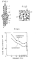
- the structure of the resistor 4 is considered to become like the one shown in Fig.2 comprising glass 42 of which particle sizes are about 10 - 500jU m, magnetic substance 41 and current path 43 mainly made of carbon and formed in a zigzag shape.
- the carbon is dispersed by the binder to adhere well to the glass 42 and magnetic substance 41.
- Materials such as zirconia, alumina, magnesia and glass of which grain sizes are less than about 5,um may be employed for the binder.
- the magnetic substance 41 absorbs high frequency noise currents, i.e., the magnetic substance 41 reduces high frequency noise currents by converting the energy of the noise currents to the magnetization energy of the spin of the magnetic substance 41 and/or to a joule heat. Therefore, the relative permeability of the magnetic substance 41 is required to be more than 10.
- the following may be used for the magnetic substance 41.
- the proportion of the magnetic substance to the resistor is limited to 0.4 - 40 wt%.
- the resistor could not show the above effects.
- more than 40 wt% magnetic susbtance is contained, due to the large energy loss at a low frequency, the performance is deteriorated.
- particle diameters of the magnetic substance are limited to 10 - 300 ⁇ m.
- the magnetic substance melts into the glass by its reaction with the glass in a heating process and thereby causes its magnetic property to be lost, its absorption of high frequency noise currents to decrease and its magnetic domain to be lost.
- the specific resistance of the magnetic substance should exceed 10 -1 ohm-cm. When the specific resistance is less than 10 -1 ohm.cm, the magnetic substance becomes conductive and thus the current path of the resistor 4 becomes too wide to obtain the aforesaid structural effect.
- the glass 42 is considered to work as an obstacle to electric currents and forms the current path 43 in a zigzag shape.
- the softening temperatures of the glass 42 should be about 300 - 600°C.
- the softening temperature of the glass 42 is preferably more than about 300° C because the spark plug is heated to about 250°C in its use. And the temperature is preferably less than 600 0 C in order to weld the resistor 4 inside the insulator 1 without oxidizing the terminal metal member 2 and the center electrode 3.
- Such glass as lithium (Li) glass, silica (SiO 2 ) glass, borosilicate glass not including lithia (Li 2 O), and soda zinc glass may be employed for the glass 42.
- Proportion of the glass to the resistor 4 is limited to 25 - 75 wt%.
- the aforesaid structural effect cannot be obtained sufficiently when the glass content in the resistor 4 is not more than 25 wt% and the amount of the magnetic substance 41 contained in the resistor 4 becomes too little if the glass content exceeds 75 wt%.
- Grain sizes of the glass 42 are preferably about 10 - 500 ⁇ m. Should the grain diameters be less than 10 ⁇ m, the glass 42 tends to soften in a normal use of the spark plug, and thereby the current path becomes unstable, and should the grain diameters exceed 500 ⁇ m, a gap tends to occur between the glass and the current path when the resistor 4 is being welded inside the insulator l.
- the current path 43 comprising 0.2 - 0.6 wt% carbon (conductor) and a binder constituting the rest are formed in a zigzag shape around the glass 42 and the magnetic substance 41.
- the spark plug of this invention is manufactured by filling and sintering and welding the resistor 4 between the terminal metal member 2 and the center electrode 3 inside the insulator 1.
- the welding temperatures are generally about 900°C.
- the spark plug of this invention includes the glass 42 and magnetic substance 41 which work as obstacles to radio noise currents and form the current path 43 in a zigzag shape and thereby provides the aforesaid structural effect. Further the magnetic substance 41 suppresses generation of radio noise currents by absorbing high frequency noise currents as mentioned before.
- spark plug of this invention An embodiment of the spark plug of this invention and comparative models were manufactured as follows. All of the spark plugs are shaped as illustrated in Fig.l.
- a mixture of carbon, glass whose grain size was 5 ⁇ m and zirconia at a proportion of 1 : 7.5 : 29 were dry-grounded for 2 hours by means of a vibration mill to produce a material for the current path.
- the glass was composed, by weight, of 52 % SiO 2 , 7 % CaO, 37 % B 2 O 3 , and 4 % Li 2 0.
- the nickel zinc ferrite was composed of 35 mol % NiO, 15 mol % ZnO, and 50 mol % Fe 2 O 3 .
- resistor materials respectively made of super permalloy and zinc oxide ferrite were also manufactured for the purpose of comparison as shown in a table.
- Fig.8 is a graph showing the measurement of the noise suppression effect using the resistors.
- the center electrode 3 was inserted in the lower end of the internal passage of the insulator 1 (alumina), then 0.26 g of copper glass which was a mixture of glass composed, by weight,of 64 % Si0 2 , 6 % Al 2 O 3 , 23 % B 2 O 3 and 7 % Na20 and copper powder at a proportion of 1 : 1 was filled on the center electrode 3, then a pressure of 1,400 kg/cm2 was applied onto the copper glass, then 0.5 g of the above-mentioned resistor material was added on the copper glass and a pressure was applied thereon in two successive process, then 0.46 g of the copper glass was placed on the resistor material, and then a pressure of 1,100 kg/cm 2 was applied on the copper glass by means of terminal nut.
- copper glass which was a mixture of glass composed, by weight,of 64 % Si0 2 , 6 % Al 2 O 3 , 23 % B 2 O 3 and 7 % Na20 and copper powder at a proportion of 1 : 1 was filled on
- the spark plug was placed in a furnace for thirty minutes at a temperature of 870°C to soften the glass contained in the materials of the copper glass and resistor. Then the spark plug was taken out of the furnace and a pressure of 1,000 kg/cm 2 was applied onto the terminal nut, and thereby the resistor material became the resistor 4 and the two pieces of copper glass become respectively the copper glass electrodes 51 and 52.
- the resistance value of the resistor 4 was controlled to comply with Japanese Industrial Standard (JIS).
- the housing 6 having an earth electrode 8 was placed around the insulator 1 to obtain the spark plug shown in Fig.l.
- a conventional spark plug A was also manufactured in the same process.
- the resister of the conventional spark plug A was composed, by weight, of 0.9 % carbon, 22.5 % zirconia, 4.5 % glass whose grain sizes are small, and 72.5 % glass whose grain sizes are large.
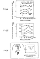
- the noise field intensity was measured with each spark plug to evaluate its noise suppressing effect. The results are shown in Figs.3 - 5.
- each spark plug was placed under 4 barometric pressures approximately equivalent to the pressure in an engine. Then a discharge aging was done for several minutes at a rotation of 2,000 rpm. Thereupon, noise field intensity was measured at various frequencies by means of a noise measuring apparatus shown in Fig.6. And, the measured values shown in Fig.3 - 5 were maximum values measured at each frequency.
- the noise field intensity of the embodiment of the spark plug of this invention is distinctly lower than that of the comparative model A at every frequency. Accordingly, the radio noise suppressing effect is enhanced by the spark plug of this invention.
- Fig.4 showing the noise suppression effects of the spark plugs, each of which is made of one of the five kinds of magnetic substances with different specific resistances and relative permeabilities indicated in Table 1; with the comparative model A being with criterion of comparison, the noise suppression effect of this invention can be obtained when the specific resistances are larger than 10 ohm cm and the relative permeabilities are more than 10.
- Fig.5 showing a comparison of noise suppression effects of various grain sizes of nickel zinc ferrite indicated as No.3 in Table 1, one of the necessary conditions for obtaining the effects of this invention is the grain sizes of the magnetic substance are larger than 10 ⁇ m.
- FIG.8 is a graph showing the measurment of the noise suppresstion effect using the resistors with varied composition weight ratio of ferrite. Since too little binder will result in instability of the resistance value, not less than 20 wt% binder is preferable. Conversely, when the binder is not less than 40 wt% and the ferrite is not less than 40 wt%, the noise suppression effect is reduced because the ferrite cannot be sealed with the binder and glass of 200 ⁇ m in grain size.
- Fig.9 shows the composition of the carbon and binder, the ferrite and the glass in the resistor of the present invention.
- the spark plug of this invention is provided with a high frequency radio wave absorbing circuit for suppressing radio noises which comprises a resistor connected between a terminal metal member and a center electrode in series.
- a magnetic substance, of which grain sizes of the glass are large, carbon and binder are employed for the material of the resistor of the spark plug.
- the spark plug of this invention absorbs high frequency radio noises by means of a magnetic substance and the current path formed in a zigzag shape by glass, of which grain sizes are large, and the magnetic substance, and thereby inhibits radio noises.
- the radio noise suppression effect of the spark plug of this invention is greatly enhanced as compared with conventional spark plugs.
Landscapes
- Chemical & Material Sciences (AREA)
- Engineering & Computer Science (AREA)
- Combustion & Propulsion (AREA)
- Spark Plugs (AREA)
Applications Claiming Priority (2)
| Application Number | Priority Date | Filing Date | Title |
|---|---|---|---|
| JP158131/84 | 1984-07-28 | ||
| JP15813184A JPS6139386A (ja) | 1984-07-28 | 1984-07-28 | 点火プラグ |
Publications (1)
| Publication Number | Publication Date |
|---|---|
| EP0170975A1 true EP0170975A1 (fr) | 1986-02-12 |
Family
ID=15664955
Family Applications (1)
| Application Number | Title | Priority Date | Filing Date |
|---|---|---|---|
| EP85109234A Ceased EP0170975A1 (fr) | 1984-07-28 | 1985-07-23 | Bougie d'allumage |
Country Status (3)
| Country | Link |
|---|---|
| EP (1) | EP0170975A1 (fr) |
| JP (1) | JPS6139386A (fr) |
| AU (1) | AU562651B2 (fr) |
Cited By (4)
| Publication number | Priority date | Publication date | Assignee | Title |
|---|---|---|---|---|
| EP0444877A2 (fr) * | 1990-02-28 | 1991-09-04 | Kabushiki Kaisha Toshiba | Résistance électrique |
| CN105308808A (zh) * | 2014-02-07 | 2016-02-03 | 日本特殊陶业株式会社 | 火花塞 |
| EP3089291A4 (fr) * | 2013-12-25 | 2017-08-30 | NGK Sparkplug Co., Ltd. | Bougie d'allumage |
| EP3312951A4 (fr) * | 2015-06-18 | 2019-03-06 | NGK Spark Plug Co., Ltd. | Bougie d'allumage |
Families Citing this family (5)
| Publication number | Priority date | Publication date | Assignee | Title |
|---|---|---|---|---|
| JP5688880B2 (ja) * | 2008-02-28 | 2015-03-25 | 日本電気硝子株式会社 | 点火プラグ用抵抗体形成用ガラス組成物 |
| JP5467495B2 (ja) * | 2008-02-28 | 2014-04-09 | 日本電気硝子株式会社 | 抵抗体形成用ガラス粉末 |
| JP5679273B2 (ja) * | 2009-09-09 | 2015-03-04 | 日本電気硝子株式会社 | 抵抗体形成材料 |
| JP5752329B1 (ja) * | 2014-02-07 | 2015-07-22 | 日本特殊陶業株式会社 | スパークプラグ |
| JP5931955B2 (ja) * | 2014-05-12 | 2016-06-08 | 日本特殊陶業株式会社 | スパークプラグ |
Citations (4)
| Publication number | Priority date | Publication date | Assignee | Title |
|---|---|---|---|---|
| FR1162823A (fr) * | 1955-12-23 | 1958-09-17 | Bosch Gmbh Robert | Dispositif de protection pour appareil de transmission sans fil, notamment sur véhicules automobiles |
| FR2270699A1 (fr) * | 1974-05-10 | 1975-12-05 | Nippon Denso Co | |
| DE3026374A1 (de) * | 1979-07-13 | 1981-01-22 | Hitachi Ltd | Widerstandsglasabdichtungs-zuendkerzen |
| DE3226340A1 (de) * | 1981-07-16 | 1983-02-03 | Ngk Spark Plug Co., Ltd., Nagoya, Aichi | Widerstandszusammensetzung fuer widerstandszuendkerzen |
-
1984
- 1984-07-28 JP JP15813184A patent/JPS6139386A/ja active Pending
-
1985
- 1985-07-23 EP EP85109234A patent/EP0170975A1/fr not_active Ceased
- 1985-07-25 AU AU45374/85A patent/AU562651B2/en not_active Ceased
Patent Citations (4)
| Publication number | Priority date | Publication date | Assignee | Title |
|---|---|---|---|---|
| FR1162823A (fr) * | 1955-12-23 | 1958-09-17 | Bosch Gmbh Robert | Dispositif de protection pour appareil de transmission sans fil, notamment sur véhicules automobiles |
| FR2270699A1 (fr) * | 1974-05-10 | 1975-12-05 | Nippon Denso Co | |
| DE3026374A1 (de) * | 1979-07-13 | 1981-01-22 | Hitachi Ltd | Widerstandsglasabdichtungs-zuendkerzen |
| DE3226340A1 (de) * | 1981-07-16 | 1983-02-03 | Ngk Spark Plug Co., Ltd., Nagoya, Aichi | Widerstandszusammensetzung fuer widerstandszuendkerzen |
Cited By (8)
| Publication number | Priority date | Publication date | Assignee | Title |
|---|---|---|---|---|
| EP0444877A2 (fr) * | 1990-02-28 | 1991-09-04 | Kabushiki Kaisha Toshiba | Résistance électrique |
| EP0444877A3 (en) * | 1990-02-28 | 1992-03-18 | Kabushiki Kaisha Toshiba | Electrical resistor element and method of manufacturing the same |
| US5182540A (en) * | 1990-02-28 | 1993-01-26 | Kabushiki Kaisha Toshiba | Electrical resistor element and method of manufacturing the same |
| EP3089291A4 (fr) * | 2013-12-25 | 2017-08-30 | NGK Sparkplug Co., Ltd. | Bougie d'allumage |
| EP3089290B1 (fr) * | 2013-12-25 | 2020-03-25 | NGK Spark Plug Co., Ltd. | Bougie d'allumage |
| CN105308808A (zh) * | 2014-02-07 | 2016-02-03 | 日本特殊陶业株式会社 | 火花塞 |
| US9614354B2 (en) | 2014-02-07 | 2017-04-04 | Ngk Spark Plug Co., Ltd. | Spark plug |
| EP3312951A4 (fr) * | 2015-06-18 | 2019-03-06 | NGK Spark Plug Co., Ltd. | Bougie d'allumage |
Also Published As
| Publication number | Publication date |
|---|---|
| JPS6139386A (ja) | 1986-02-25 |
| AU4537485A (en) | 1986-01-30 |
| AU562651B2 (en) | 1987-06-18 |
Similar Documents
| Publication | Publication Date | Title |
|---|---|---|
| US4713582A (en) | Spark plug | |
| KR100844613B1 (ko) | 입자 표면이 내산화성 금속으로 피복된 자기 분말을포함하는 본드 자석으로 이루어진 자기 코어 및 그 자기코어를 포함하는 인덕턴스 부품 | |
| EP0170975A1 (fr) | Bougie d'allumage | |
| EP0316015A2 (fr) | Matériau pour résistance et résistance non linéaire ainsi préparée | |
| DE3501558C3 (de) | Pulvermischung zur Herstellung eines elektrischen Widerstands in einer Zündkerze | |
| EP2190085B1 (fr) | Isolateur pour bougie d'allumage et bougie d'allumage comportant cet isolateur | |
| US5807510A (en) | Electric resistance element exhibiting voltage nonlinearity characteristic and method of manufacturing the same | |
| US4933659A (en) | Voltage non-linear resistor and method of producing the same | |
| US5225111A (en) | Voltage non-linear resistor and method of producing the same | |
| JPS6139385A (ja) | 点火プラグ | |
| JP3175500B2 (ja) | 電圧非直線抵抗体およびその製造方法 | |
| GB2145075A (en) | Material for high-frequency suppression and a distributor for an internal combustion engine having an electrode composed of such material | |
| US3737718A (en) | Ignition noise suppression center electrode assembly for spark plugs | |
| JPH0945458A (ja) | 抵抗入りプラグ | |
| JPS61135079A (ja) | 抵抗入点火プラグ | |
| JPS61104580A (ja) | 点火プラグ | |
| US4270266A (en) | Method of making a dielectric containing material for RF suppression | |
| JP3538032B2 (ja) | 電圧非直線性抵抗体磁器組成物及び電圧非直線性抵抗体 | |
| JPH0548594B2 (fr) | ||
| JP2002083708A (ja) | 酸化物磁性材料とその製造方法および積層チップインダクタ | |
| JP6267779B1 (ja) | スパークプラグ | |
| JPH0346668B2 (fr) | ||
| JPS61208768A (ja) | 抵抗入りプラグ | |
| JP2001326108A (ja) | 電圧非直線抵抗体およびその製造方法 | |
| JPH07169613A (ja) | 複合磁性体材料 |
Legal Events
| Date | Code | Title | Description |
|---|---|---|---|
| PUAI | Public reference made under article 153(3) epc to a published international application that has entered the european phase |
Free format text: ORIGINAL CODE: 0009012 |
|
| AK | Designated contracting states |
Designated state(s): DE FR GB |
|
| 17P | Request for examination filed |
Effective date: 19860207 |
|
| 17Q | First examination report despatched |
Effective date: 19870413 |
|
| STAA | Information on the status of an ep patent application or granted ep patent |
Free format text: STATUS: THE APPLICATION HAS BEEN REFUSED |
|
| 18R | Application refused |
Effective date: 19880723 |
|
| RIN1 | Information on inventor provided before grant (corrected) |
Inventor name: YAMADA, MANABU Inventor name: YOSHIDA, ICHIROU Inventor name: YAMAGUCHI, SHUNZO |