EP0170513A2 - Fiberskop zur Verwendung bei sehr niedrigen Temperaturen - Google Patents
Fiberskop zur Verwendung bei sehr niedrigen Temperaturen Download PDFInfo
- Publication number
- EP0170513A2 EP0170513A2 EP85305396A EP85305396A EP0170513A2 EP 0170513 A2 EP0170513 A2 EP 0170513A2 EP 85305396 A EP85305396 A EP 85305396A EP 85305396 A EP85305396 A EP 85305396A EP 0170513 A2 EP0170513 A2 EP 0170513A2
- Authority
- EP
- European Patent Office
- Prior art keywords
- body tube
- image guide
- objective lens
- image
- fiberscope
- Prior art date
- Legal status (The legal status is an assumption and is not a legal conclusion. Google has not performed a legal analysis and makes no representation as to the accuracy of the status listed.)
- Granted
Links
- 239000000835 fiber Substances 0.000 claims description 37
- 230000002093 peripheral effect Effects 0.000 claims description 22
- 238000004891 communication Methods 0.000 claims description 18
- 239000003822 epoxy resin Substances 0.000 claims description 12
- 229920000647 polyepoxide Polymers 0.000 claims description 12
- 239000013307 optical fiber Substances 0.000 claims description 11
- 229910052738 indium Inorganic materials 0.000 claims description 9
- APFVFJFRJDLVQX-UHFFFAOYSA-N indium atom Chemical compound [In] APFVFJFRJDLVQX-UHFFFAOYSA-N 0.000 claims description 9
- KCTAWXVAICEBSD-UHFFFAOYSA-N prop-2-enoyloxy prop-2-eneperoxoate Chemical compound C=CC(=O)OOOC(=O)C=C KCTAWXVAICEBSD-UHFFFAOYSA-N 0.000 claims description 8
- 229910052751 metal Inorganic materials 0.000 claims description 5
- 239000002184 metal Substances 0.000 claims description 5
- 239000004593 Epoxy Substances 0.000 claims description 4
- 239000000853 adhesive Substances 0.000 claims description 4
- ATJFFYVFTNAWJD-UHFFFAOYSA-N Tin Chemical compound [Sn] ATJFFYVFTNAWJD-UHFFFAOYSA-N 0.000 claims description 2
- 150000002739 metals Chemical class 0.000 claims 1
- 239000001307 helium Substances 0.000 abstract description 23
- 229910052734 helium Inorganic materials 0.000 abstract description 23
- SWQJXJOGLNCZEY-UHFFFAOYSA-N helium atom Chemical compound [He] SWQJXJOGLNCZEY-UHFFFAOYSA-N 0.000 abstract description 23
- 230000005540 biological transmission Effects 0.000 abstract description 22
- 239000007788 liquid Substances 0.000 abstract description 21
- 238000010791 quenching Methods 0.000 description 9
- 230000000171 quenching effect Effects 0.000 description 9
- 238000009833 condensation Methods 0.000 description 5
- 230000005494 condensation Effects 0.000 description 5
- 230000008014 freezing Effects 0.000 description 5
- 238000007710 freezing Methods 0.000 description 5
- 239000007789 gas Substances 0.000 description 5
- 238000004519 manufacturing process Methods 0.000 description 5
- 238000010276 construction Methods 0.000 description 3
- 238000001514 detection method Methods 0.000 description 3
- 230000000694 effects Effects 0.000 description 3
- 239000000463 material Substances 0.000 description 3
- 238000011084 recovery Methods 0.000 description 3
- 208000024891 symptom Diseases 0.000 description 3
- IJGRMHOSHXDMSA-UHFFFAOYSA-N Atomic nitrogen Chemical compound N#N IJGRMHOSHXDMSA-UHFFFAOYSA-N 0.000 description 2
- ATUOYWHBWRKTHZ-UHFFFAOYSA-N Propane Chemical compound CCC ATUOYWHBWRKTHZ-UHFFFAOYSA-N 0.000 description 2
- 238000000034 method Methods 0.000 description 2
- 230000008569 process Effects 0.000 description 2
- 239000010935 stainless steel Substances 0.000 description 2
- 229910001220 stainless steel Inorganic materials 0.000 description 2
- -1 160°C Chemical compound 0.000 description 1
- 229910000978 Pb alloy Inorganic materials 0.000 description 1
- 229910001128 Sn alloy Inorganic materials 0.000 description 1
- 229910045601 alloy Inorganic materials 0.000 description 1
- 239000000956 alloy Substances 0.000 description 1
- 238000005452 bending Methods 0.000 description 1
- 230000015572 biosynthetic process Effects 0.000 description 1
- 230000008859 change Effects 0.000 description 1
- 230000008602 contraction Effects 0.000 description 1
- 238000001816 cooling Methods 0.000 description 1
- 230000006837 decompression Effects 0.000 description 1
- 230000003292 diminished effect Effects 0.000 description 1
- 239000011521 glass Substances 0.000 description 1
- 230000006872 improvement Effects 0.000 description 1
- 230000001678 irradiating effect Effects 0.000 description 1
- 239000003949 liquefied natural gas Substances 0.000 description 1
- 230000008018 melting Effects 0.000 description 1
- 238000002844 melting Methods 0.000 description 1
- 238000012986 modification Methods 0.000 description 1
- 230000004048 modification Effects 0.000 description 1
- 229910052757 nitrogen Inorganic materials 0.000 description 1
- 239000001294 propane Substances 0.000 description 1
- 239000010453 quartz Substances 0.000 description 1
- 230000009467 reduction Effects 0.000 description 1
- VYPSYNLAJGMNEJ-UHFFFAOYSA-N silicon dioxide Inorganic materials O=[Si]=O VYPSYNLAJGMNEJ-UHFFFAOYSA-N 0.000 description 1
- 238000007738 vacuum evaporation Methods 0.000 description 1
Images

Classifications
-
- G—PHYSICS
- G02—OPTICS
- G02B—OPTICAL ELEMENTS, SYSTEMS OR APPARATUS
- G02B23/00—Telescopes, e.g. binoculars; Periscopes; Instruments for viewing the inside of hollow bodies; Viewfinders; Optical aiming or sighting devices
- G02B23/24—Instruments or systems for viewing the inside of hollow bodies, e.g. fibrescopes
- G02B23/26—Instruments or systems for viewing the inside of hollow bodies, e.g. fibrescopes using light guides
-
- G—PHYSICS
- G02—OPTICS
- G02B—OPTICAL ELEMENTS, SYSTEMS OR APPARATUS
- G02B23/00—Telescopes, e.g. binoculars; Periscopes; Instruments for viewing the inside of hollow bodies; Viewfinders; Optical aiming or sighting devices
- G02B23/24—Instruments or systems for viewing the inside of hollow bodies, e.g. fibrescopes
- G02B23/2476—Non-optical details, e.g. housings, mountings, supports
- G02B23/2492—Arrangements for use in a hostile environment, e.g. a very hot, cold or radioactive environment
Definitions
- the present invention relates to a very-low-temperature fiberscope used in liquefied gas of very low temperature, such as liquefied natural gas, liquefied propane gas, liquid nitrogen, liquid helium, etc.
- the superconductive magnet device generally comprises a cryostat, a superconductive coil housed in the cryostat, and liquid helium for cooling the coil to very low temperature.
- a quenching phenomenon such that the superconductive coil is shifted from a superconducting state to a normal conducting state, may present itself from some cause.
- the superconductive coil is connected with a detection system for electrically detecting the quenching phenomenon, an energy recovery circuit being connected to both ends of the superconductive coil when an output is delivered from the detection system.
- the energy recovery circuit is connected so late that the superconductive coil is very liable to be burned.
- it is to be desired that a symptom of the phenomenon is detected in advance so that the energy recovery circuit can be connected to the superconductive coil immediately on detection of the symptom.
- Such a symptom may be perceived by production of air bubbles from the surface region of the coil, or by deformation of the coil itself.
- the quenching phenomenon takes place when the temperature of a part of the superconductive coil is increased slightly, triggering a sudden increase in the temperature of the entire coil.
- the temperature of the coil is increased slightly in the initial stage of the quenching phenomenon, the liquid helium in contact with the surface of the coil is heated to produce air bubbles therein. Accordingly, presentation of the quenching phenomenon can be foreseen by observing the production of air bubbles near the surface of the coil.
- the quenching phenomenon may also be caused by a distortion of the superconductive coil resulting from some external force. Therefore, development of the quenching phenomenon may be expected when the start of coil deformation is observed. In other words, observation of the surface conditions of the superconductive coil enables us to foresee a subsequent development of the quenching phenomenon.
- a fiberscope may be used as an image transmission system which comprises an image guide consisting of a plurality of optical fibers in a bunch, an objective lens unit attached to one end of the image guide and etc.
- the objective lens unit and part of the image guide are immersed in the liquid helium contained in the cryostat, the helium being of a very low temperature of, for example, about 4.2 K. If the fiberscope used is intended for normal-temperature use, freezing or dew condensation will, possibly, ensue on the end face of the image guide or the surfaces of the objective lenses, constituting a hindrance to satisfactory observation.
- the present invention is contrived in consideration of these circumstances, and is intended to provide a very-low-temperature fiberscope capable of preventing freezing and/or dew condensation on both the end face of the image guide and the surfaces of the objective lenses, thereby permitting satisfactory observation of an object kept at very low temperature.
- a fiberscope which comprises a light source; a light guide, extending from the light source to a position near an object of observation in a very-low-temperature region and adapted to lead light emitted from the light source onto the object; an image guide, having one end located in the vicinity of the object and the other end outside the very-low-temperature region and adapted to lead an image of the object to the outside of the very-low-temperature region; an objective lens unit fixed to the one end of the image guide, the objective lens unit including a body tube extending from the one end of the image guide and at least one objective lens whose one side faces said one end of the image guide and whose other side faces the object to project the image of the object onto said one end face of the image guide, the inside of the body tube being kept under vacuum; and an eyepiece fixed to the other end of the image guide and through which the object is viewed.
- a fiberscope which comprises a light source; a light guide, extending from the light source to a position near an object of observation in a very-low-temperature region and adapted to lead light emitted from the light source onto the object; an image guide, having one end located in the vicinity of the object and the other end outside the very-low-temperature region and adapted to lead an image of the object to the outside of the very-low-temperature region; an objective lens unit fixed to the one end of the image guide, the objective lens unit including a body tube extending from the one end of the image guide, at least one objective lens whose one side faces said one end of the image guide and whose other side faces the object to project the image of the object onto the one end face of the image guide, and the inside space of the body tube communicating with the outside thereof; and an eyepiece fixed to the other end of the image guide and through which the object is viewed.
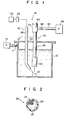
- a fiberscope 14 used for observation of a sample kept at very low temperature.
- numeral 10 designates a cryostat containing liquid helium therein as a very-low-temperature liquefied gas.
- the sample 12 is held in the cryostat 10.
- a vacuum pump 13 is connected to the cryostat 10 by means of a pipe 11.
- the fiberscope 14 is mainly composed of an irradiation system 16 for irradiating the sample 12, and a transmission system 18 for transmitting an image of the sample 12.
- the irradiation system 16 includes a light source 20, a filter 22 for intercepting infrared components of light emitted from the light source and a light guide 24 for leading the light transmitted through the filter 22 to the sample 12.
- One end of the light guide 24 is connected ' to the light source 20 through the filter 22, while the other end thereof extends close to the sample 12 through the top wall of the cryostat 10.
- the light guide 24 applies the light emitted from the light source 20 to the top surface of the sample 12.
- the light guide 24 includes a cylindrical optical fiber bundle 26 consisting of a number of optical fibers 25, and a sheath 28 covering the outer peripheral surface of the fiber bundle 26.
- the sheath 28 is formed of covering material such as epoxy resin, preferably epoxy acrylate.
- the thickness of the sheath 28 is set to be one fourth or less of the diameter of the fiber bundle 26.
- the transmission system 18 is provided with an image guide 36 which includes a cylindrical fiber bundle 32 consisting of a number of optical fibers 30 and a sheath 33 covering the outer peripheral surface of the fiber bundle 32.
- the sheath 33 is formed of epoxy resin, preferably epoxy acrylate, its thickness being one fourth or less of the diameter of the fiber bundle 32.
- a flexible covering tube 34 formed of, for example, stainless steel, is disposed outside of the image guide 36, extending coaxial therewith and spaced therefrom.
- an annular exhaust passage 35 is defined between the image guide 36 and the covering tube 34.
- the lower half portion of the image guide 18 extends through the top wall of the cryostat 10 into the liquid helium.
- Fiber holders 38 and 39 are fixed to the upper and lower end portions of the image guide 36, respectively. These holders 38 and 39 are each in the form of a hollow cylinder having an inner diameter substantially equal to the diameter of the image guide 36. Each end portion of the image guide 36 is fixedly inserted into the bore of its corresponding holder 38 or 39.
- a connecting tube 40 is hermetically fixed to the outer periphery of the holder 38, and a suction pipe 42 is connected to the connecting tube 40.
- An eyepiece 44 is fixed to the upper end of the connecting tube 40, facing the top end face of the fiber bundle 32.
- the upper end of the covering tube 34 is fixed to the lower end of the connecting tube 40.
- the suction pipe 42 is connected to a vacuum pump 46, and a valve 48 is provided at the middle portion of the suction pipe 42.
- An objective lens unit 51 including a body tube 50, is fixed to the fiber holder 39.
- the fiber holder 39 is inserted into the upper end portion of the body tube 50 and hermetically fixed to the inner peripheral surface of the body tube 50.
- the lower end of the covering tube 34 is fixed to the upper end of the body tube 50.
- the lower half portion of the body tube 50 extends from the holder 39 to a position near the sample 12.
- the bottom opening of the body tube 50 is closed by a transparent plate 52 so that the inside of the body tube 50 is kept airtight.
- First, second and third objective lenses 54, 55 and 56 are arranged within the body tube 50 so as to be coaxial therewith.
- a pair of semicircular lens holders 58 are fixed to the outer peripheral edge of each objective lens by means of, e.g., an epoxy-based adhesive agent whose adhesiveness will never be diminished even at very low temperatures. Threading is formed on the inner peripheral surface of the body tube 50 so that the lenses 54, 55 and 56, with their corresponding lens holders 58 thereon, are screwed into the body tube 50.
- a pair of communication passages 60 are defined between the lens holders 58.
- the space between the first lens 54 and the bottom end face of the fiber bundle 32, the space between the first and second lenses 54 and 55, the space between the second and third lenses 55 and 56, and the space between the third lens and transparent plate 52 communicate with one another by means of the communication passages 60.
- a pair of communication grooves 62 are formed in the fiber holder 39 to extend in the axial direction of the body tube 50. These communication grooves 62 communicate with the inside space of the body tube 50 and the exhaust passage 35.
- a pair of communication grooves 64 are formed in the fiber holder 38 to extend in the axial direction thereof. These communication grooves 64 communicate with the exhaust passage 35.
- An annular groove 66 is formed in the holder 38, whereby the two communication grooves 64 are connected to each other. The annular groove 66 communicates with the suction pipe 42.
- the vacuum pump 46 can communicate with the inside space of the body tube 50 by means of the suction pipe 42, the annular groove 66, the communication grooves 64, the exhaust passage 35 and the communication grooves 62.
- the sample 12 placed in the liquid helium in the cryostat 10 is observed as follows.
- the sample 12 is placed in the cryostat 10 and the irradiation system 16 and the transmission system 18 of the fiberscope 14 are then set in place, as shown in Fig. 1.
- the valve 48 is opened and the vacuum pump 46 is actuated to exhaust the interior of the transmission system 18.
- the inside space of the body tube 50 communicates with the vacuum pump 46 by means of the communication grooves 62, the exhaust passage 35, the communication grooves 64, the annular groove 66, and the suction pipe 42, so that air and steam in the inside space of the body tube 50 is sucked out by the vacuum pump 46, carried on an exhaust current.
- the valve 48 is closed.
- the inside of the transmission system 18, including that of the body tube 50 is sealed under vacuum.
- the inside of the system 18 may be sealed after it is exhausted.
- the valve 48 may be kept open to continue the exhaust from the transmission system 18 till the end of the observation.
- the cryostat 10 is exhausted and decompressed by the vacuum pump 13. Then, liquid helium is poured into the cryostat 10. Thereafter, the light source 20 is actuated, and a light, with its infrared components intercepted by the filter 22, is applied to the sample 12 through the light guide 24. The light reflected by the sample 12 is projected through the transparent plate 52 into the body tube 50, imaged by the objective lenses 54, 55 and 56, and then delivered to the eyepiece 44 through the image guide 36.
- the fiberscope 14 with the aforementioned construction has the following advantages.
- the inside of the body tube 50 is kept under vacuum, so that no air or steam exists around the objective lenses 54, 55 and 56. Accordingly, even if the body tube 50 is immersed in the liquid helium to be cooled inside, neither freezing nor dew condensation will ensue on the surfaces of the objective lenses, the bottom end face of the fiber bundle 32, or the inner surface of the transparent plate 52. Thus, the sample 12 can be clearly observed. If a light containing infrared components is applied to liquid helium, the liquid helium absorbs the infrared components. As a result, a number of air bubbles are produced in the liquid helium, constituting a hindrance to the observation of the sample 12. According to this embodiment, however, the infrared components of the light to be projected into the liquid helium are intercepted by the filter 22, so that the condition of the sample 12 can be satisfactorily observed without impediment by the production of air bubbles.
- the light guide 34 and the image guide 36 have their respective sheaths 28 and 33 formed of epoxy acrylate.
- This sheath material is higher in refractive index than the quartz used as the material for the optical fibers, thus providing a better contrast.
- the sheaths 28 and 33 cannot easily peel off, even if they are cooled to very low temperature. Having a thickness equal to one fourth or less of the diameter of their corresponding fiber bundles 26 and 32, the sheaths 28 and 33 are low in contraction coefficient even when they are cooled to very low temperature. If the sheaths 28 and 33 have a greater thickness, they will possibly contract greatly when cooled, bending the optical fibers by their compressive force. In this case, the optical fibers will not be able to securely transmit the light, thereby failing to provide a good contrast.
- This embodiment offers a solution to this problem.
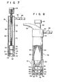
- the transmission system of the fiberscope may be constructed as shown in Fig. 7.
- like reference numerals are used to designate like portions as included in the first embodiment.
- a transmission system 18 includes an image guide 36 which is formed of a fiber bundle 32 and a sheath 33.
- An eyepiece 44 is fixed to the upper end of the image guide 36, while a body tube 50 is hermetically fixed to the lower end.
- the bottom opening of the body tube 50 is closed by a transparent plate 52.
- a pair of objective lenses 54 and 55 are arranged in the body tube 50, facing the bottom end face of the image guide 36 and the transparent plate 42, respectively.
- An outer tube 70 is disposed outside of the body tube 50 and the image guide 36. One end of the outer tube 70 is fixed to the lower end of the body tube 50, while the other end is fixed to the intermediate portion of the image guide 36.
- the outer tube 70 is connected with a suction pipe 42 which, opening into the exhaust passage 35, is connected to a vacuum pump.
- the suction pipe 42 is fitted with a valve 48.
- the objective lenses 54 and 55 are each firmly fixed to the inner peripheral surface of the body tube 50 by means of a soft metal or alloy layer, e.g., an indium layer 74.
- a soft metal or alloy layer e.g., an indium layer 74.
- the following are processes for fixing the objective lenses 54 and 55 to the body tube 50 with the aid of the indium layers 74.
- the indium layers 74 with a thickness of about 0.2 to 0.3 mm, are formed individually on the peripheral edge portions of the objective lenses 54 and 55 by vacuum evaporation.
- the objective lenses 54 and 55, with their corresponding indium layers 74 thereon are force-fitted into the body tube 50.
- the fixing operation is finished.
- Communication ports 75, 76 and 77 are bored through those portions of the peripheral wall of the body tube 50 which are located between the bottom end face of the image guide 36 and the objective lens 54, between the objective lenses 54 and 55, and between the objective lens 55 and the transparent plate 52, respectively.
- the inside space of the body tube 50 can communicate with the vacuum pump by means of the communication ports 75, 76 and 77, the exhaust passage 35, and the suction pipe 42.
- the fiberscope with the aforementioned construction may provide the same effect as those of the first embodiment.
- the transmission system 18 When the transmission system 18 is exhausted by actuating the vacuum pump with the valve 48 open, air and steam in the inside space of the body tube 50 is discharged, carried by an exhaust current, to the outside of the transmission system 18 through the communication ports 75, 76 and 77, the exhaust passage 35 and the suction pipe 42.
- the inside of the body tube 50 is kept under vacuum.
- the objective lenses 54 and 55 are fixed to the body tube 50 by means of the indium layers 74.
- Indium is an element whose mechanical strength does not change even at a very low temperature of about 4.2 K, it having a thermal expansion coefficient resembling that of the glass which forms the objective lenses. Therefore, even when the transmission system 18 is repeatedly used at normal temperature and at very low temperature, no gaps will be formed between the objective lenses 54 and 55 and the inner surface of the body tube 50. Thus, there will be no possibility of the objective lenses slipping out of the body tube 50, or of the body tube 50 losing its airtight seal.
- the whole body tube 50 may be heated to a temperature higher than the melting point (156.4°C) of indium, e.g., 160°C, kept at that temperature for about one minute, and then cooled.
- the objective lenses 54 and 55 can be soldered to the body tube 50 for greater fixity.
- the objective lenses may be fixed as follows. First, the body tube 50 is heated and the objective lenses, in a cooled state, are then inserted into the body tube 50. Thereafter, the body tube 50 is cooled to fix the objective lenses therein.
- the body tube 50 may be externally pressurized and crimped to fixedly hold the objective lenses after the objective lenses are inserted into the body tube 50.
- Fig. 8 shows a fiberscope according to a third embodiment of the present invention, in which irradiation and transmission systems are formed integrally.
- like reference numerals are used to designate like portions as included in the first embodiment.
- a light guide 24 and an image guide 36 are formed from a common fiber bundle 78; the central portion of the fiber bundle 78 constitutes the image guide 36 and the outer peripheral portion the light guide 24.
- the outer peripheral surface of the fiber bundle 78 is covered with a sheath 80 made of epoxy resin.
- a covering-tube 34 made of stainless steel is disposed outside of the fiber bundle 78, and an annular exhaust passage 35 is defined between the covering tube 34 and the fiber bundle 78.
- a body tube 50 is fixed to the lower end portions of the fiber bundle 78 and the covering tube 34.
- the body tube 50 has an inner bore 81 and a plurality of vertical holes 82 spaced and arranged outside of the inner bore 81 along the circumference thereof.
- the bottom openings of the inner bore 81 and the vertical holes 82 are hermetically closed by a transparent plate 52.
- a plurality of segments of the light guide 24 are individually inserted into the vertical holes 82.
- a lens 84 for diffusing light is disposed in each of the vertical holes 82 such that it faces the bottom end face of each corresponding light guide segment.
- the image guide 36 is inserted in the inner bore 81, and a pair of objective lenses 54 and 55 are arranged in the inner bore 81 to face the bottom end face of the image guide 36.
- Communication ports 86 for connecting the inner bore 81 and the vertical holes 82 are formed in those portions of the wall of the body tube 50 located between the inner bore 81 and the vertical holes 82.
- the communication ports 86 are located on either side of the lenses 84.
- An exhaust groove 88 is formed in the inner peripheral surface of the inner bore 81 to extend from the bottom to the top of the body tube 50 along the axial direction thereof.
- the upper end portion of the fiber bundle 78 is divided into two parts constituting the light guide 24 and the image guide 36.
- the light guide 24 is connected to a light source through a filter, while an eyepiece 44 is fixed to the upper end of the image guide 36.
- the same effect of the first embodiment can be produced by evacuating the inner bore 81 and the vertical holes 82 of the tube 50.
- the integral formation of the irradiation and transmission systems leads to a reduction in size and an improvement in the operativity of the fiberscope.
- the body tube is evacuated by means of the vacuum pump.
- the body tube may be exclusively sealed as a vacuum after its manufacture.
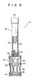
- Fig. 9 shows a transmission system of a fiberscope according to a fourth embodiment of the present invention.
- the irradiation system is constructed in the same manner as that of the first embodiment.
- a transmission system 18 is provided with an image guide 36 which includes a fiber bundle 32 and a sheath 33 formed on the outer peripheral surface of the fiber bundle 32.
- the sheath 33 is formed of epoxy resin such as epoxy acrylate, and has a thickness equal to one fourth or less of the diameter of the fiber bundle 32.
- An eyepiece 44 is fixed to the upper end of the image guide 36 while a body tube 50 is fixed to the lower end, by means of a holder 39, SO as to be coaxial with the image guide 36.
- a pair of objective lenses 54 and 55 are fixed within the body tube 50, facing the bottom end face of the image guide 36, by means of an epoxy-based adhesive agent.
- Three sets of apertures 90, 92 and 94 are circumferentially formed in those portions of the outer peripheral wall of the body tube 50 which are located between the bottom end face of the image guide 36 and the objective lens 54, between the two objective lenses 54 and 55, and below the objective lens 55, respectively.
- a plurality of apertures 96 are circumferentially formed in the top wall of the body tube 50.
- the body tube side is inserted into a cryostat so that the objective lens 55 faces a sample.
- the sample placed in the cryostat is observed as follows.
- the irradiation system and the transmission system 18 of the fiberscope are set in position in the cryostat. Then, the cryostat is exhausted by a vacuum pump. When the exhaust process ends, helium gas is introduced into the cryostat, following which liquid helium is poured into the cryostat to a predetermined level. Thereupon, part of the liquid helium flows into the body tube 50 through the apertures 90, 92, 94 and 96 therein, finally filling the body tube 50. As a result, air and steam in the body tube 50 are forced out of the body tube by the liquid helium.
- the supply of liquid helium is stopped, and the cryostat is decompressed to a predetermined pressure level by the vacuum pump. By this decompression, air bubbles sticking to the surfaces of the objective lenses 54 and 55 are removed. After the air bubbles are removed, helium gas is introduced into the cryostat to restore the pressure therein to one atmosphere.
- the light source is actuated so that observation of the sample can be performed through the eyepiece 44.
- behavior of the sample at a very low temperature can be visually monitored.
- layers of liquid helium are formed between the bottom end face of the image guide 36 and the objective lens 54, and between the two objective lenses 54 and 55 during the observation of the sample. It is to be understood, therefore, that the distances between the bottom end face of the image guide and the objective lens 54, and between the two objective lenses 54 and 55 should be set in consideration of the refractive index of the liquid helium layers.
Landscapes
- Physics & Mathematics (AREA)
- Astronomy & Astrophysics (AREA)
- General Physics & Mathematics (AREA)
- Optics & Photonics (AREA)
- Instruments For Viewing The Inside Of Hollow Bodies (AREA)
- Endoscopes (AREA)
- Microscoopes, Condenser (AREA)
Applications Claiming Priority (8)
| Application Number | Priority Date | Filing Date | Title |
|---|---|---|---|
| JP16058284A JPS6139007A (ja) | 1984-07-31 | 1984-07-31 | 極低温下で使用される対物レンズ装置の製造方法 |
| JP160582/84 | 1984-07-31 | ||
| JP59175417A JPS6152602A (ja) | 1984-08-23 | 1984-08-23 | 極低温用フアイバ−スコ−プ |
| JP175417/84 | 1984-08-23 | ||
| JP10872185A JPS61267014A (ja) | 1985-05-21 | 1985-05-21 | 極低温用ファイバ−スコ−プ |
| JP108723/85 | 1985-05-21 | ||
| JP10872385A JPH063497B2 (ja) | 1985-05-21 | 1985-05-21 | 極低温用フアイバ−スコ−プ |
| JP108721/85 | 1985-05-21 |
Publications (3)
| Publication Number | Publication Date |
|---|---|
| EP0170513A2 true EP0170513A2 (de) | 1986-02-05 |
| EP0170513A3 EP0170513A3 (en) | 1986-05-14 |
| EP0170513B1 EP0170513B1 (de) | 1988-10-19 |
Family
ID=27469656
Family Applications (1)
| Application Number | Title | Priority Date | Filing Date |
|---|---|---|---|
| EP85305396A Expired EP0170513B1 (de) | 1984-07-31 | 1985-07-29 | Fiberskop zur Verwendung bei sehr niedrigen Temperaturen |
Country Status (3)
| Country | Link |
|---|---|
| US (1) | US4707075A (de) |
| EP (1) | EP0170513B1 (de) |
| DE (1) | DE3565724D1 (de) |
Cited By (1)
| Publication number | Priority date | Publication date | Assignee | Title |
|---|---|---|---|---|
| EP0922983A1 (de) * | 1997-12-12 | 1999-06-16 | Carl Zeiss | VUV-beständige Verbindungstechnik für Linsen und Fassungen |
Families Citing this family (8)
| Publication number | Priority date | Publication date | Assignee | Title |
|---|---|---|---|---|
| JPH0797167B2 (ja) * | 1987-01-14 | 1995-10-18 | 住友電気工業株式会社 | 光バンドルフアイバの端末構造 |
| US5208644A (en) * | 1990-05-18 | 1993-05-04 | Xinix, Inc. | Interference removal |
| US5381508A (en) * | 1993-08-25 | 1995-01-10 | Krumenacher; Paul F. | Suction and light guide assembly |
| WO2006113916A2 (en) * | 2005-04-20 | 2006-10-26 | The Regents Of The University Of California | Crytogenic immersion microscope |
| JP5504173B2 (ja) | 2007-12-31 | 2014-05-28 | ボストン サイエンティフィック サイムド,インコーポレイテッド | 血管分岐部の処置のためのカテーテルアセンブリ |
| DE102015118641A1 (de) * | 2015-10-30 | 2017-05-04 | Carl Zeiss Microscopy Gmbh | Vorrichtung zum optischen Untersuchen einer Probe, Verfahren zum Untersuchen einer Probe und Verfahren zum Versetzen einer Vorrichtung in einen betriebsbereiten Zustand |
| GB201605182D0 (en) * | 2016-03-24 | 2016-05-11 | Air Bp Ltd | Viewing system for fluid vessel |
| FR3075960B1 (fr) * | 2017-12-22 | 2020-06-19 | Commissariat A L'energie Atomique Et Aux Energies Alternatives | Dispositif de mesure d'un rayonnement retrodiffuse par un echantillon et procede de mesure utilisant un tel dispositif. |
Family Cites Families (8)
| Publication number | Priority date | Publication date | Assignee | Title |
|---|---|---|---|---|
| CA961158A (en) * | 1971-01-08 | 1975-01-14 | Bruce W. Dobras | Optical reader |
| US3709612A (en) * | 1971-03-10 | 1973-01-09 | Miles Lab | Apparatus for measuring reflected light under stabilized light source conditions |
| JPS5457039U (de) * | 1977-09-28 | 1979-04-20 | ||
| CA1120904A (en) * | 1978-11-06 | 1982-03-30 | American Optical Corporation | Endoscope |
| JPS56102228A (en) * | 1980-01-17 | 1981-08-15 | Olympus Optical Co | Endoscope |
| JPS59124312A (ja) * | 1982-12-29 | 1984-07-18 | Sumitomo Electric Ind Ltd | 画像観察装置 |
| FR2543261B1 (fr) * | 1983-03-25 | 1985-08-16 | Gaz De France | Dispositif d'observation a l'interieur d'un reservoir cryogenique en service |
| JPS6042730A (ja) * | 1983-08-18 | 1985-03-07 | Olympus Optical Co Ltd | 内視鏡 |
-
1985
- 1985-07-24 US US06/758,402 patent/US4707075A/en not_active Expired - Fee Related
- 1985-07-29 EP EP85305396A patent/EP0170513B1/de not_active Expired
- 1985-07-29 DE DE8585305396T patent/DE3565724D1/de not_active Expired
Cited By (2)
| Publication number | Priority date | Publication date | Assignee | Title |
|---|---|---|---|---|
| EP0922983A1 (de) * | 1997-12-12 | 1999-06-16 | Carl Zeiss | VUV-beständige Verbindungstechnik für Linsen und Fassungen |
| US5991101A (en) * | 1997-12-12 | 1999-11-23 | Carl-Zeiss-Stiftung | UV-resistant jointing technique for lenses and mounts |
Also Published As
| Publication number | Publication date |
|---|---|
| EP0170513B1 (de) | 1988-10-19 |
| US4707075A (en) | 1987-11-17 |
| EP0170513A3 (en) | 1986-05-14 |
| DE3565724D1 (en) | 1988-11-24 |
Similar Documents
| Publication | Publication Date | Title |
|---|---|---|
| EP0170513B1 (de) | Fiberskop zur Verwendung bei sehr niedrigen Temperaturen | |
| US5992728A (en) | Endoscope | |
| EP0399684B1 (de) | Laser-Modul mit optischer Faser und Methode zu seiner Herstellung | |
| US4904046A (en) | Process of and apparatus for leading an optical waveguide through a wall via a hermetic seal | |
| CA2004858A1 (en) | Fiber optic canister having orthotropic, controlled thermal expansion bobbin | |
| JPH0395510A (ja) | 光ファイバ結合手段を有する光学的組立品 | |
| US20030174974A1 (en) | Optical communication part and method of fabricating the same | |
| US4902091A (en) | Light waveguide feedthrough for optoelectronic modules and method for their manufacture | |
| US20060115202A1 (en) | Fibre optic based semiconductor micro sensors for sensing pressure or temperature, fabrication methods of said sensors, and a method of securing an optical fibre to a silicon block | |
| JP3183810B2 (ja) | 光通信用モジュール | |
| EP0031146B1 (de) | Koppelmontage einer Lichtleitfaser und einer Lichtquelle und Verfahren zu deren Zusammenbau | |
| JPH03501171A (ja) | 堅固化構造を有する光ファイバ貫通アセンブリ | |
| JPH08262279A (ja) | 光ファイバ光源組立体 | |
| US5774613A (en) | Ferrule for an optical fiber connector | |
| US4209228A (en) | Pressure-light endoscope | |
| US20240310193A1 (en) | Off-axis fiber optic sensor | |
| JPH063497B2 (ja) | 極低温用フアイバ−スコ−プ | |
| JP2509582B2 (ja) | 光フアイバコリメ−タ | |
| JP3542842B2 (ja) | 光気密アダプタ | |
| JPH0342644B2 (de) | ||
| US20240280427A1 (en) | Optical pressure sensor and manufacturing method therefor | |
| JP2000121874A (ja) | フェルール付き光ファイバ及びその製造方法 | |
| JPH0453287B2 (de) | ||
| KR0149794B1 (ko) | 가변 광필터 | |
| JPH04350602A (ja) | 光ファイバ接続構造 |
Legal Events
| Date | Code | Title | Description |
|---|---|---|---|
| PUAI | Public reference made under article 153(3) epc to a published international application that has entered the european phase |
Free format text: ORIGINAL CODE: 0009012 |
|
| 17P | Request for examination filed |
Effective date: 19850808 |
|
| AK | Designated contracting states |
Designated state(s): DE FR GB |
|
| PUAL | Search report despatched |
Free format text: ORIGINAL CODE: 0009013 |
|
| AK | Designated contracting states |
Kind code of ref document: A3 Designated state(s): DE FR GB |
|
| 17Q | First examination report despatched |
Effective date: 19870714 |
|
| GRAA | (expected) grant |
Free format text: ORIGINAL CODE: 0009210 |
|
| AK | Designated contracting states |
Kind code of ref document: B1 Designated state(s): DE FR GB |
|
| REF | Corresponds to: |
Ref document number: 3565724 Country of ref document: DE Date of ref document: 19881124 |
|
| ET | Fr: translation filed | ||
| PLBE | No opposition filed within time limit |
Free format text: ORIGINAL CODE: 0009261 |
|
| STAA | Information on the status of an ep patent application or granted ep patent |
Free format text: STATUS: NO OPPOSITION FILED WITHIN TIME LIMIT |
|
| 26N | No opposition filed | ||
| PGFP | Annual fee paid to national office [announced via postgrant information from national office to epo] |
Ref country code: FR Payment date: 19980610 Year of fee payment: 14 |
|
| PGFP | Annual fee paid to national office [announced via postgrant information from national office to epo] |
Ref country code: GB Payment date: 19980720 Year of fee payment: 14 |
|
| PGFP | Annual fee paid to national office [announced via postgrant information from national office to epo] |
Ref country code: DE Payment date: 19980930 Year of fee payment: 14 |
|
| PG25 | Lapsed in a contracting state [announced via postgrant information from national office to epo] |
Ref country code: GB Free format text: LAPSE BECAUSE OF NON-PAYMENT OF DUE FEES Effective date: 19990729 |
|
| PG25 | Lapsed in a contracting state [announced via postgrant information from national office to epo] |
Ref country code: FR Free format text: THE PATENT HAS BEEN ANNULLED BY A DECISION OF A NATIONAL AUTHORITY Effective date: 19990731 |
|
| GBPC | Gb: european patent ceased through non-payment of renewal fee |
Effective date: 19990729 |
|
| PG25 | Lapsed in a contracting state [announced via postgrant information from national office to epo] |
Ref country code: DE Free format text: LAPSE BECAUSE OF NON-PAYMENT OF DUE FEES Effective date: 20000503 |
|
| REG | Reference to a national code |
Ref country code: FR Ref legal event code: ST |