EP0170449B1 - Steuersystem für die Tintentropfengeschwindigkeit - Google Patents
Steuersystem für die Tintentropfengeschwindigkeit Download PDFInfo
- Publication number
- EP0170449B1 EP0170449B1 EP85304924A EP85304924A EP0170449B1 EP 0170449 B1 EP0170449 B1 EP 0170449B1 EP 85304924 A EP85304924 A EP 85304924A EP 85304924 A EP85304924 A EP 85304924A EP 0170449 B1 EP0170449 B1 EP 0170449B1
- Authority
- EP
- European Patent Office
- Prior art keywords
- ink
- controller
- flow rate
- nozzle
- drop velocity
- Prior art date
- Legal status (The legal status is an assumption and is not a legal conclusion. Google has not performed a legal analysis and makes no representation as to the accuracy of the status listed.)
- Expired - Lifetime
Links
- 238000000034 method Methods 0.000 claims abstract description 9
- 230000008859 change Effects 0.000 claims abstract description 6
- 239000002904 solvent Substances 0.000 claims description 32
- 230000011664 signaling Effects 0.000 claims description 8
- 230000001105 regulatory effect Effects 0.000 claims description 5
- 230000001276 controlling effect Effects 0.000 claims description 4
- 238000005086 pumping Methods 0.000 claims 2
- 230000009471 action Effects 0.000 abstract description 8
- 239000000758 substrate Substances 0.000 abstract description 7
- 239000000976 ink Substances 0.000 description 143
- 238000005259 measurement Methods 0.000 description 12
- 238000010586 diagram Methods 0.000 description 9
- 239000007788 liquid Substances 0.000 description 8
- 238000001816 cooling Methods 0.000 description 6
- 230000007423 decrease Effects 0.000 description 6
- 230000003247 decreasing effect Effects 0.000 description 6
- 238000010438 heat treatment Methods 0.000 description 6
- 230000006870 function Effects 0.000 description 4
- 230000000694 effects Effects 0.000 description 3
- 235000014676 Phragmites communis Nutrition 0.000 description 2
- 238000013459 approach Methods 0.000 description 2
- 230000005484 gravity Effects 0.000 description 2
- 239000000203 mixture Substances 0.000 description 2
- 239000007787 solid Substances 0.000 description 2
- 244000273256 Phragmites communis Species 0.000 description 1
- 230000008021 deposition Effects 0.000 description 1
- 230000005684 electric field Effects 0.000 description 1
- 239000012530 fluid Substances 0.000 description 1
- 238000009472 formulation Methods 0.000 description 1
- 230000007246 mechanism Effects 0.000 description 1
- 230000004048 modification Effects 0.000 description 1
- 238000012986 modification Methods 0.000 description 1
- 238000012544 monitoring process Methods 0.000 description 1
- 238000011017 operating method Methods 0.000 description 1
- 238000002360 preparation method Methods 0.000 description 1
- 230000003134 recirculating effect Effects 0.000 description 1
- 230000009467 reduction Effects 0.000 description 1
- 230000004044 response Effects 0.000 description 1
- 230000001360 synchronised effect Effects 0.000 description 1
- 238000005303 weighing Methods 0.000 description 1
Images


Classifications
-
- B—PERFORMING OPERATIONS; TRANSPORTING
- B41—PRINTING; LINING MACHINES; TYPEWRITERS; STAMPS
- B41J—TYPEWRITERS; SELECTIVE PRINTING MECHANISMS, i.e. MECHANISMS PRINTING OTHERWISE THAN FROM A FORME; CORRECTION OF TYPOGRAPHICAL ERRORS
- B41J2/00—Typewriters or selective printing mechanisms characterised by the printing or marking process for which they are designed
- B41J2/005—Typewriters or selective printing mechanisms characterised by the printing or marking process for which they are designed characterised by bringing liquid or particles selectively into contact with a printing material
- B41J2/01—Ink jet
- B41J2/07—Ink jet characterised by jet control
- B41J2/125—Sensors, e.g. deflection sensors
-
- B—PERFORMING OPERATIONS; TRANSPORTING
- B41—PRINTING; LINING MACHINES; TYPEWRITERS; STAMPS
- B41J—TYPEWRITERS; SELECTIVE PRINTING MECHANISMS, i.e. MECHANISMS PRINTING OTHERWISE THAN FROM A FORME; CORRECTION OF TYPOGRAPHICAL ERRORS
- B41J2/00—Typewriters or selective printing mechanisms characterised by the printing or marking process for which they are designed
- B41J2/005—Typewriters or selective printing mechanisms characterised by the printing or marking process for which they are designed characterised by bringing liquid or particles selectively into contact with a printing material
- B41J2/01—Ink jet
- B41J2/015—Ink jet characterised by the jet generation process
- B41J2/02—Ink jet characterised by the jet generation process generating a continuous ink jet
-
- B—PERFORMING OPERATIONS; TRANSPORTING
- B41—PRINTING; LINING MACHINES; TYPEWRITERS; STAMPS
- B41J—TYPEWRITERS; SELECTIVE PRINTING MECHANISMS, i.e. MECHANISMS PRINTING OTHERWISE THAN FROM A FORME; CORRECTION OF TYPOGRAPHICAL ERRORS
- B41J2/00—Typewriters or selective printing mechanisms characterised by the printing or marking process for which they are designed
- B41J2/005—Typewriters or selective printing mechanisms characterised by the printing or marking process for which they are designed characterised by bringing liquid or particles selectively into contact with a printing material
- B41J2/01—Ink jet
- B41J2/015—Ink jet characterised by the jet generation process
- B41J2/04—Ink jet characterised by the jet generation process generating single droplets or particles on demand
- B41J2/045—Ink jet characterised by the jet generation process generating single droplets or particles on demand by pressure, e.g. electromechanical transducers
- B41J2/04501—Control methods or devices therefor, e.g. driver circuits, control circuits
- B41J2/04571—Control methods or devices therefor, e.g. driver circuits, control circuits detecting viscosity
-
- B—PERFORMING OPERATIONS; TRANSPORTING
- B41—PRINTING; LINING MACHINES; TYPEWRITERS; STAMPS
- B41J—TYPEWRITERS; SELECTIVE PRINTING MECHANISMS, i.e. MECHANISMS PRINTING OTHERWISE THAN FROM A FORME; CORRECTION OF TYPOGRAPHICAL ERRORS
- B41J2/00—Typewriters or selective printing mechanisms characterised by the printing or marking process for which they are designed
- B41J2/005—Typewriters or selective printing mechanisms characterised by the printing or marking process for which they are designed characterised by bringing liquid or particles selectively into contact with a printing material
- B41J2/01—Ink jet
- B41J2/015—Ink jet characterised by the jet generation process
- B41J2/04—Ink jet characterised by the jet generation process generating single droplets or particles on demand
- B41J2/045—Ink jet characterised by the jet generation process generating single droplets or particles on demand by pressure, e.g. electromechanical transducers
- B41J2/04501—Control methods or devices therefor, e.g. driver circuits, control circuits
- B41J2/04586—Control methods or devices therefor, e.g. driver circuits, control circuits controlling heads of a type not covered by groups B41J2/04575 - B41J2/04585, or of an undefined type
-
- B—PERFORMING OPERATIONS; TRANSPORTING
- B41—PRINTING; LINING MACHINES; TYPEWRITERS; STAMPS
- B41J—TYPEWRITERS; SELECTIVE PRINTING MECHANISMS, i.e. MECHANISMS PRINTING OTHERWISE THAN FROM A FORME; CORRECTION OF TYPOGRAPHICAL ERRORS
- B41J2/00—Typewriters or selective printing mechanisms characterised by the printing or marking process for which they are designed
- B41J2/005—Typewriters or selective printing mechanisms characterised by the printing or marking process for which they are designed characterised by bringing liquid or particles selectively into contact with a printing material
- B41J2/01—Ink jet
- B41J2/17—Ink jet characterised by ink handling
- B41J2/195—Ink jet characterised by ink handling for monitoring ink quality
Definitions
- This invention relates to the field of drop marking systems of the type in which a liquid ink is forced under pressure through a nozzle which converts the liquid into droplets which can then be controlled by various means while projected toward a substrate for marking purposes.
- Examples of such systems include the familiar ink jet marking systems used for high speed label printing, product identification and the like, although there are other drop marking systems known in the art.
- One particular type of system which advantageously employs the present invention is the continuous stream, synchronous ink jet printer.
- Such a system typically includes an ink reservoir and a remotely located nozzle connected to the reservoir by a conduit. Ink is forced under pressure from the reservoir to the nozzle which emits a continuous stream of ink drops.
- the ink which is electrically conductive, is provided with a charge as the drops leave the nozzle.
- the drops then pass through a deflection field which causes selected drops to be deflected so that some of the drops are deposited onto a substrate while the remaining drops are returned to the reservoir by a suitable ink return means.
- ink drops In order to produce high quality marking, it is important that the ink drops pass through the deflection field at a relatively constant velocity. Thus, ink drops with similar charges but different velocities will experience unequal amounts of deflection resulting in inconsistent print quality.
- the present invention by sensing the flow of the ink from the reservoir and generating ink flow rate data, monitors the velocity of the drops of ink in the charge field and adjusts the ink parameters to maintain a desired flow rate which insures a substantially constant drop velocity.
- the present invention provides direct control over the velocity of the ink drops and does so by use of low cost components arranged in a simple manner.
- an ink drop velocity controller for a drop marking system having an ink supply reservoir, a nozzle to form a stream of ink drops, and a pressure source to force the ink to the nozzle from the reservoir
- the controller being characterised in that it comprises means for directly measuring the ink flow rate from the reservoir to the nozzle and consequently the time interval required for an established volume of ink to flow to the nozzle, controller means responsive to the measuring means for comparing said time interval against a reference value to identify deviations from the latter, and means responsive to the controller means for altering the ink flow rate to maintain said time interval substantially equal to said reference value.
- a method for controlling ink drop velocity in a drop marking system having an ink supply, a nozzle to form a stream of ink drops, and a pressure source to force the ink to the nozzle, from the supply, said method comprising the steps of directly measuring the ink flow rate from the reservoir to the nozzle and consequently the time interval required for a known volume of ink to flow to the nozzle comparing the time interval against a reference value to identify deviations therefrom, and altering the ink flow rate to maintain said time interval substantially equal to said reference value.
- the present invention provides direct feedback control of ink drop velocity.
- the invention eliminates the need for drop counters and evaporated loss measurement schemes of the prior art.
- the present invention measures the length of time required for a given volume of ink to flow through the ink jet nozzle.
- This information is supplied to a suitable electronic controller (for example, a microprocessor) to control one or more subsystems which cause a change in the ink flow rate as, for example, by changing the system pressure or the ink viscosity.
- a suitable electronic controller for example, a microprocessor
- the ink flow rate and drop velocity is initially set, by adjustment of the pressure in the ink flow line, to a condition which yields proper drop spacing.
- the present invention then forces perpetuation of a constant flow rate through the nozzle orifice resulting in a stream of ink drops of essentially unchanging velocity whereby accurate deflection of the ink drops for accurate deposition of certain drops onto the substrate can be achieved.
- the ink flow information which is obtained at a location remote from the nozzle orifice, represents the velocity of the drops projected from the nozzle so that such velocity can be accurately maintained.
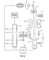
- FIG. 1 a generalized schematic of the invention, applied to a typical ink drop marking system, is shown.
- a typical marking system a plurality of ink drops 10, separated by a spacing D, emanate from an ink jet nozzle 12 having an orifice 14.
- the nozzle is acted upon by a piezo electric device 18 in a manner well known in the art (see, for example, U.S. Patent No. 3,512,172).
- the drops pass adjacent a charging electrode 17 and then through an electrical deflection field schematically represented by plates 19.
- Ink flows to the nozzle 12 by way of a flexible conduit 20 from a pressurized supply tank 22 which is usually remotely located from the print head.
- a supply tank may supply ink to several ink jet nozzles.
- the supply tank 22 is repetitively filled by suitable means which comprise a part of the ink recirculation system designated generally at 24.
- suitable means which comprise a part of the ink recirculation system designated generally at 24.
- recirculating systems may have many forms as is known in the art.
- a recirculation system will include an ink drop return mechanism such as the collector 26 positioned to receive ink drops which are not projected onto a substrate 27 and a conduit 28 to return the unused ink to the recirculation system 24 and then to the reservoir 22.
- Typical ink recirculation systems also include means for adding additional ink and solvent in order to make up for depletion during operation.
- a suitable substantially constant pressure source for example, gas pressure is supplied to the tank or reservoir 22 to cause ink flow from the reservoir to the nozzle.
- a compressed gas (air) pressure source 30 is provided which is a regulated source as disclosed, for example, in U.S. Patent No. 4,067,020.
- the supply tank or reservoir chamber 22 is filled with an electrically conductive ink to some arbitrarily determined level as indicated at C for example.
- the level of ink in the tank decreases until it reaches a second, arbitrarily determined level as indicated at A.
- a first level detector 32 is activated signalling an electronic controller 34 which initiates a time interval.
- Ink continues to flow out of the nozzle causing a drop in the tank level until at some later time the level of the ink in the supply tank reaches a third, arbitrarily determined level as indicated at B.
- a second liquid level detector 36 is activated signalling the controller 34 to cease measurement of the time interval.
- the controller When the controller receives this second signal, it compares the time interval or the average of a succession of such intervals to an established reference interval. If necessary the controller then initiates suitable action, as will be described, to force the ink flow rate through the nozzle to change such that successive time intervals will approach the reference interval.
- the level of ink in the tank 22 after passing point B may continue to fall until some suitable level as indicated at D is reached.
- the ink recirculation system 24 refills the supply tank.
- point D will usually be the same as point B so that upon completing measurement of the time interval between points A and B, the recirculation system will refill the tank to level C in preparation for the next time interval measurement.
- the liquid level detectors 32 and 36 provide their input to an electronic controller 34.
- the detector may be of any commercially available type as, for example, a magnetic float which actuates a common reed switch whereby a change in state of the reed switch (open to close or vice versa) is detected by the controller 34.
- the controller may be a solid state logic system or a programmed computer as, for example, a microprocessor computer system. Responsive to the switches 32 and 34, the controller will activate one or more output devices under its control as indicated schematically in Figure 1. These devices include ink heating and/or cooling means 40, pressure control means 42 and solvent control means 44. In addition, the controller may operate an information display, such as a LED or LCD display, to provide information to an operator concerning the status of the system as indicated at 46.
- an information display such as a LED or LCD display
- the specific means 40 through 44 are discussed in detail in connection with the embodiments of Figures 2 through 6. However, it can be seen that the invention is directly responsive to the flow rate data derived from the flow of ink between points A and B.
- the electronic controller adjusts system operation to insure that the flow rate of ink through the nozzle orifice 14 is such as to insure constant velocity of the ink drops through the electrically charged field. This results in a much more accurate placement of the ink drops on a substrate.
- the controller has a reference time for the flow of an established quantity of ink, that is the quantity of ink extant between the points A and B, set either by being programmed in or manually entered by the system operator or computed by the electronic controller.
- the velocity of the drops is set. For example, pressure is adjusted until the desired drop velocity is obtained in the operating system.
- the controller stores and averages a number of measurements of time required for the ink to pass between levels A and B. Typically, ten measurements may be used.
- the reference time is compared against the average time of the actual measurements.
- the reference may be multiplied by the number of actual measurements and the comparison performed. If the actual measurements are greater than the reference, it is necessary to increase flow through the nozzle orifice. This can be effected by a number of possible actions contemplated by the present invention: (1) solvent may be added to the ink to lower its viscosity; (2) the pressure driving the ink to the nozzle may be increased; or (3) the ink temperature may be increased by heating thereby lowering ink viscosity.
- the computed total is less than the reference value, it is necessary to decrease the flow rate through the nozzle orifice and opposite actions are required. For example, simply not adding solvent to the ink will increase its viscosity due to the normal evaporative losses as the ink circulates through the marking system. Alternatively, the ink pressure can be decreased or a cooler can be used to cool the ink or a heating system turned off.
- the controller repeats the above actions to maintain a substantially constant measured time interval which corresponds to a substantially constant ink flow rate and that, in turn, corresponds to a substantially constant ink drop velocity.
- the rate at which the measurement cycles occur is a function of the size of the supply tank, typically on the order of 10 ml, the precision required and a number of related factors including whether or not the system is utilized for one ink jet nozzle or multiple nozzles. For example, with a single ink jet head it may be sufficient to check flow rate at approximately one minute intervals but shorter or longer intervals may also be employed.
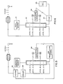
- the ink recirculation system includes a pump 50 supplying ink to the tank 22 from the catcher 26, the associated ink return means 52 and a reservoir 54 which receives fresh ink from a tank 56 and solvent from a tank 58.
- pump 50 accomplishes this by drawing fluid from the reservoir 54 into the tank 22.
- the contents of the reservoir will be mixture of fresh ink, return ink and solvent in proportions determined, in part, by the electronic controller as will be described.
- the electronic controller determines that the flow rate of ink through the tank is below the set point value, it adds solvent to the system. This is accomplished by permitting the controller to operate a valve 60 in the line 62 between the solvent tank 58 and the reservoir 54. Programmed into the controller is the flow rate of the solvent through the conduit 62 whereby the controller can determine the amount of solvent to be added and thereafter shut off the valve 60. Alternatively, the controller can be programmed to operate the valve for a fixed length of time thereby to add a known amount of solvent each time that it detects solvent is required and to continue adding solvent on subsequent operating cycles until solvent is no longer required.
- the reservoir 54 contains fresh ink from the tank 56, return ink from the ink catcher 26 via return means 52 and the associated vacuum source 53, and solvent from the tank 58.
- the entry of fresh ink into the reservoir 54 can be controlled by a suitable detector 70 which opens a valve 72 whenever the liquid in the reservoir 54 drops below a specified level.
- the Figure 2 embodiment measures the time interval for the ink to flow between the levels A and B in the tank 22 and makes a comparison of the data representing the flow rate against a standard value. If the flow rate is too great, it does not add make up solvent from container 58. Accordingly, as solvent evaporates viscosity increases and flow rate decreases toward the reference value. If the flow rate is insufficient, the electronic controller operates valve 60 adding solvent to the reservoir 54 thereby lowering the viscosity of the ink sent to tank 22 so that subsequent operation of the print head will result in an increased flow rate thereby to maintain the directed drop velocity.
- FIG. 3 a first alternative embodiment is disclosed.
- the electronic controller operates a pressure regulator 74 which controls the gas pressure from source 30.
- a pressure regulator 74 which controls the gas pressure from source 30.
- a second alternate embodiment is disclosed.
- the electronic controller operates a liquid pressure regulator 76 which acts on the ink flowing through the conduit 20.
- the ink in the supply tank 22 is pressurized by the usual gas source 30 to a pressure higher than is required to feed ink to the nozzle.
- the final ink delivery pressure to the orifice is, in turn, controlled by the regulator 76 which is instead responsive to the electronic controller.
- a third alternate embodiment of the invention is disclosed.
- temperature-viscosity relationship of the ink is employed.
- Ink viscosity decreases with increasing temperature and vice versa.
- the electronic controller operates heating and/or cooling elements indicated at 80 and 82, respectively, disposed in the supply line from the tank to the nozzle. It will be apparent that only one of these units need be employed whereby viscosity can be decreased by turning on the heater and increased by turning it off or, conversely, viscosity can be increased by cooling the ink and increased by turning off the cooling unit.
- FIG. 6 A final embodiment of the invention is disclosed in Figure 6.
- the output of a pump 84 is changed responsive to the electronic controller.
- Pump 84 at the end of each measurement period, supplies fresh ink from a reservoir 85 to refill the tank 22.
- the output of the pump 84 is increased when an increase in ink pressure is needed.
- the output of the pump is decreased when the controller requires a reduction in ink pressure.
- the gas pressure source 31 differs from the sources 30 used in the previous embodiments.
- Source 31 is a back pressure device which does not maintain a constant pressure in the tank.
- the pump 84 increases its output, the ink pressure will be higher and vice versa.
- the action of the pump 84 in supplying make up ink to the tank alters the ink pressure to the nozzle.
- FIG. 7A a flow diagram describing a manner of programming the computer embodiment of the electronic controller is disclosed.
- the main operating routine Prior to operation of the system it is necessary to initialize it which includes providing the number of reads per cycle of operation as well as the reference value.
- the main operating routine is entered. This is indicated at point A in Figure 7A.
- the first activity is to make sure that the switch and float associated with point A in the ink tank is in the correct position to begin sensing ink flow.
- a debounce routine is provided as indicated at 100.
- the system will not initiate operation, by arming the switch A, until it has verified that the tank has been refilled, the switch is in the correct position and has stopped oscillating or "bouncing".
- switch A is armed and enabled to signal the controller when the ink level drops below point A, as indicated at 102.
- the computer then enters a loop indicated at 103 in which it repetitively monitors switch A until it detects that the switch has opened at which time the counting interval begins as indicated at 104.
- the program next enters a second loop monitoring the state of switch B until it too is detected as open as indicated at 105.
- switch B opens it is detected and the counting interval terminates and the time of the interval is read by the program at 106 and stored in an appropriate memory location.
- the time for this interval is then added to the time for the previous reads in a particular cycle as indicated at 107. As previously indicated, however, it is possible, instead of accumulating a total of previous reads, to average them in which case a different reference value would be utilized.
- the program next checks to see if the number of reads or times that a counting interval has been completed equals the number specified during system initialization. If not, the program branches back to the beginning and conducts further counting intervals.
- the program branches to 109 where a comparison is made of the total time for all intervals against the reference value.
- Box 109 represents the type of program which would be utilized for the preferred embodiment of Figure 2 as well as for the embodiment of Figure 5 in which the viscosity of the ink is altered responsive to the need for adjustment in the flow rate.
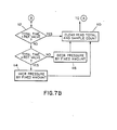
- Figure 7B discloses the appropriate portion of the flow diagram for the remaining embodiments as will be discussed presently.
- the solvent valve 60 is actuated adding solvent to the reservoir 54 which, in turn, is supplied to the tank 22 resulting in a reduced viscosity for the ink and an increased flow rate.
- the ink heater would be activated to warm the ink sufficiently to reduce its viscosity, achieving the same result.
- the program would be reversed so that if the ink were flowing too quickly, cooling would be turned on whereas if it were flowing too slowly, cooling would be turned off. After the solvent or temperature control activity indicated at 111 occurs, the program branches back to the beginning via subroutine 110.
- Figure 7B the modification to the flow diagram required for the embodiments of Figures 3, 4 and 6 is disclosed.
- Figure 7B replaces the portion of the Figure 7A flow diagram from point B on.
- the program makes a comparison.
- the first comparison is whether the total time is equal to the reference value. If so, no pressure adjustment is required and accordingly the program branches, via subroutine 110 back to the beginning. If, however, the total time does not equal the reference value, it is necessary to determine if the total time is greater than or less than the reference value. If greater, as indicated at 114, pressure is increased by a fixed amount and the program branches back to the beginning. If the total time is less than the reference value, it is necessary to decrease the pressure, as indicated at 116, and then the program branches back.
Landscapes
- Engineering & Computer Science (AREA)
- Quality & Reliability (AREA)
- Particle Formation And Scattering Control In Inkjet Printers (AREA)
- Ink Jet (AREA)
- Facsimile Heads (AREA)
- Fax Reproducing Arrangements (AREA)
- Extrusion Moulding Of Plastics Or The Like (AREA)
Claims (17)
Priority Applications (1)
| Application Number | Priority Date | Filing Date | Title |
|---|---|---|---|
| AT85304924T ATE51802T1 (de) | 1984-08-03 | 1985-07-10 | Steuersystem fuer die tintentropfengeschwindigkeit. |
Applications Claiming Priority (2)
| Application Number | Priority Date | Filing Date | Title |
|---|---|---|---|
| US06/637,404 US4555712A (en) | 1984-08-03 | 1984-08-03 | Ink drop velocity control system |
| US637404 | 1991-01-04 |
Publications (3)
| Publication Number | Publication Date |
|---|---|
| EP0170449A2 EP0170449A2 (de) | 1986-02-05 |
| EP0170449A3 EP0170449A3 (en) | 1986-06-04 |
| EP0170449B1 true EP0170449B1 (de) | 1990-04-11 |
Family
ID=24555778
Family Applications (1)
| Application Number | Title | Priority Date | Filing Date |
|---|---|---|---|
| EP85304924A Expired - Lifetime EP0170449B1 (de) | 1984-08-03 | 1985-07-10 | Steuersystem für die Tintentropfengeschwindigkeit |
Country Status (6)
| Country | Link |
|---|---|
| US (1) | US4555712A (de) |
| EP (1) | EP0170449B1 (de) |
| JP (2) | JPS6141555A (de) |
| AT (1) | ATE51802T1 (de) |
| CA (1) | CA1238238A (de) |
| DE (1) | DE3577062D1 (de) |
Families Citing this family (46)
| Publication number | Priority date | Publication date | Assignee | Title |
|---|---|---|---|---|
| US4651161A (en) * | 1986-01-17 | 1987-03-17 | Metromedia, Inc. | Dynamically varying the pressure of fluid to an ink jet printer head |
| GB8708884D0 (en) * | 1987-04-14 | 1987-05-20 | Domino Printing Sciences Plc | Control of ink jet printing system |
| GB8725465D0 (en) * | 1987-10-30 | 1987-12-02 | Linx Printing Tech | Ink jet printers |
| US4860027A (en) * | 1988-03-18 | 1989-08-22 | A. B. Dick Company | Ink drop control system with temperature compensation |
| US4827280A (en) * | 1988-08-09 | 1989-05-02 | A. B. Dick Company | Flow rate control system |
| US4845512A (en) * | 1988-10-12 | 1989-07-04 | Videojet Systems International, Inc. | Drop deflection device and method for drop marking systems |
| GB9009957D0 (en) * | 1990-05-03 | 1990-06-27 | Domino Printing Sciences Plc | Ink supply system for continuous ink jet printer |
| CA2049454C (en) * | 1990-10-18 | 1999-01-05 | Michael E. Stamer | Automatic character height control for ink jet printers |
| US5418557A (en) * | 1991-10-03 | 1995-05-23 | Videojet Systems International, Inc. | Drop quality control system for jet printing |
| GB9205343D0 (en) * | 1992-03-12 | 1992-04-22 | Willett Int Ltd | Temperature control system |
| US5517216A (en) * | 1992-07-28 | 1996-05-14 | Videojet Systems International, Inc. | Ink jet printer employing time of flight control system for ink jet printers |
| US5424766A (en) * | 1993-11-08 | 1995-06-13 | Videojet Systems International, Inc. | Ink jet printer control system responsive to acoustical properties of ink |
| US5623292A (en) * | 1993-12-17 | 1997-04-22 | Videojet Systems International, Inc. | Temperature controller for ink jet printing |
| US5583544A (en) * | 1994-10-06 | 1996-12-10 | Videojet Systems International, Inc. | Liquid level sensor for ink jet printers |
| DE4443526C1 (de) * | 1994-12-07 | 1995-12-21 | Daimler Benz Ag | Lamellendach für ein Kraftfahrzeug |
| US5805178A (en) * | 1995-04-12 | 1998-09-08 | Eastman Kodak Company | Ink jet halftoning with different ink concentrations |
| AUPN234595A0 (en) * | 1995-04-12 | 1995-05-04 | Eastman Kodak Company | Improvements in image halftoning |
| US6003965A (en) * | 1995-09-01 | 1999-12-21 | Videojet Systems International, Inc. | Ink and solvent container for ink jet printers |
| GB9603813D0 (en) | 1996-02-22 | 1996-04-24 | Videojet Systems Int | An ink jet printing system |
| US5980034A (en) * | 1996-03-11 | 1999-11-09 | Videojet Systems International, Inc. | Cross flow nozzle system for an ink jet printer |
| US6920400B2 (en) * | 1998-05-01 | 2005-07-19 | United Electric Controls Co. | Method and apparatus for detecting a plugged port |
| JPH11348261A (ja) * | 1998-06-10 | 1999-12-21 | Canon Inc | 液体噴射記録ヘッドにおける液体吐出状態検査方法および液体吐出状態検査装置 |
| JP2000158624A (ja) * | 1998-09-25 | 2000-06-13 | Fuji Photo Film Co Ltd | 平版印刷方法 |
| US6513434B1 (en) * | 1999-05-17 | 2003-02-04 | Fuji Photo Film Co., Ltd. | On-press recording type lithographic printing method and apparatus |
| DE60038491T2 (de) * | 1999-05-31 | 2009-05-07 | Fujifilm Corp. | Lithographisches verfahren und lithographische vorrichtung, verfahren und vorrichtung zur herstellung einer druckplatte und verfahren und vorrichtung zum tintenstrahldrucken |
| EP1142713B9 (de) * | 1999-11-05 | 2010-07-21 | Seiko Epson Corporation | Aufzeichnungsgerät des tintenstrahltyps und verfahren zur tintenversorgung für den untertank mittels desselben gertes und verfahren zur kontrolle der dem untertank zugeführten tintenmenge mittels desselben gerätes |
| US6631983B2 (en) * | 2000-12-28 | 2003-10-14 | Eastman Kodak Company | Ink recirculation system for ink jet printers |
| US6471327B2 (en) * | 2001-02-27 | 2002-10-29 | Eastman Kodak Company | Apparatus and method of delivering a focused beam of a thermodynamically stable/metastable mixture of a functional material in a dense fluid onto a receiver |
| TW526413B (en) * | 2001-08-28 | 2003-04-01 | Asustek Comp Inc | Connector capable of displaying version of computer connection interface |
| AU2003215357A1 (en) * | 2002-02-22 | 2003-09-09 | Terrasimco Inc. | Bladder-based apparatus and method for dispensing coatings |
| US6832699B2 (en) * | 2002-02-22 | 2004-12-21 | Terrasimco Inc. | Direct pressure apparatus and method for dispensing coatings |
| US6830320B2 (en) * | 2002-04-24 | 2004-12-14 | Eastman Kodak Company | Continuous stream ink jet printer with mechanism for asymmetric heat deflection at reduced ink temperature and method of operation thereof |
| US6615004B1 (en) | 2002-05-06 | 2003-09-02 | Hewlett-Packard Development Company, L.P. | Supplying marking fluid in an imaging system |
| US7207652B2 (en) * | 2003-10-17 | 2007-04-24 | Lexmark International, Inc. | Balanced satellite distributions |
| BRPI0509056A (pt) | 2004-03-31 | 2007-08-21 | Ajinomoto Kk | bactéria pertencendo ao gênero bacillus ou ao gênero escherichia, e, métodos para produzir um nucleosìdeo de purina, para produzir um nucleotìdeo de purina e para produzir ácido 5'-guanìlico |
| US20070251330A1 (en) * | 2006-04-13 | 2007-11-01 | Delaware Capital Formation, Inc. | Flowmeter |
| JP4664268B2 (ja) * | 2006-11-30 | 2011-04-06 | 紀州技研工業株式会社 | インクジェットプリンタ |
| GB0720289D0 (en) * | 2007-10-12 | 2007-11-28 | Videojet Technologies Inc | Ink jet printer |
| US8020980B2 (en) | 2007-10-16 | 2011-09-20 | Silverbrook Research Pty Ltd | Printer with reservoir headspace pressure control |
| WO2011020022A1 (en) * | 2009-08-13 | 2011-02-17 | Sun Chemical Corporation | Temperature control in gravure and flexographic printing by aqueous fluid injection into the ink |
| US10112385B2 (en) | 2014-10-31 | 2018-10-30 | Hewlett-Packard Development Company, L.P. | Ambient temperature based flow rates |
| FR3048200B1 (fr) * | 2016-02-26 | 2019-07-12 | Dover Europe Sarl | Procede et dispositif d'ajout de solvant par petites quantites |
| JP7227029B2 (ja) * | 2019-02-18 | 2023-02-21 | 株式会社Screenホールディングス | 印刷装置およびインク供給方法 |
| EP3741571A1 (de) * | 2019-05-24 | 2020-11-25 | Paul Leibinger GmbH & Co. KG Nummerier- und Markierungssysteme | Verfahren zur überwachung und einstellung der tintenviskosität während des betriebs eines continuous inkjet druckers und continuous inkjet drucker zur durchführung eines solchen verfahrens |
| CN110239216B (zh) * | 2019-07-25 | 2024-05-24 | 北京博源恒芯科技股份有限公司 | 基于can-lin协议的负压墨路系统 |
| GB2606168B (en) * | 2021-04-27 | 2025-01-22 | Domino Uk Ltd | Wash valve |
Family Cites Families (14)
| Publication number | Priority date | Publication date | Assignee | Title |
|---|---|---|---|---|
| US3930258A (en) * | 1975-01-13 | 1975-12-30 | Dick Co Ab | Ink monitoring and automatic fluid replenishing apparatus for ink jet printer |
| US4067020A (en) * | 1976-09-20 | 1978-01-03 | A. B. Dick Company | Noninterrupt ink transfer system for ink jet printer |
| US4130126A (en) * | 1977-05-31 | 1978-12-19 | International Business Machines Corporation | Ink maintenance sensor |
| US4121222A (en) * | 1977-09-06 | 1978-10-17 | A. B. Dick Company | Drop counter ink replenishing system |
| FR2405819A1 (fr) * | 1977-10-13 | 1979-05-11 | Dick Co Ab | Moyens pour l'alimentation en encre d'un dispositif d'impression par jet d'encre |
| JPS55109667A (en) * | 1979-02-19 | 1980-08-23 | Ricoh Co Ltd | Ink feeder for ink jet printer |
| JPS5646445A (en) * | 1979-09-21 | 1981-04-27 | Kagome Kk | Viscometer |
| US4382382A (en) * | 1979-11-01 | 1983-05-10 | General Electric Company | Multilevel liquid sensing system |
| JPS5670962A (en) * | 1979-11-16 | 1981-06-13 | Ricoh Co Ltd | Controlling method for ink density |
| JPS5672962A (en) * | 1979-11-19 | 1981-06-17 | Ricoh Co Ltd | Detecting device for viscosity of ink in ink-jet printing device |
| JPS56136381A (en) * | 1980-03-28 | 1981-10-24 | Sharp Corp | Control of viscosity of jet ink |
| JPS5821542A (ja) * | 1981-07-31 | 1983-02-08 | Shimadzu Corp | 流れ試験機 |
| JPS5962156A (ja) * | 1982-10-01 | 1984-04-09 | Oki Electric Ind Co Ltd | インクジエツト記録装置 |
| JPS5973956A (ja) * | 1982-10-20 | 1984-04-26 | Ricoh Co Ltd | インクジエツト記録装置 |
-
1984
- 1984-08-03 US US06/637,404 patent/US4555712A/en not_active Expired - Lifetime
-
1985
- 1985-07-10 DE DE8585304924T patent/DE3577062D1/de not_active Expired - Lifetime
- 1985-07-10 EP EP85304924A patent/EP0170449B1/de not_active Expired - Lifetime
- 1985-07-10 AT AT85304924T patent/ATE51802T1/de not_active IP Right Cessation
- 1985-07-24 JP JP16215485A patent/JPS6141555A/ja active Pending
- 1985-07-31 CA CA000487832A patent/CA1238238A/en not_active Expired
-
1992
- 1992-08-10 JP JP1992056039U patent/JP2574861Y2/ja not_active Expired - Lifetime
Also Published As
| Publication number | Publication date |
|---|---|
| EP0170449A2 (de) | 1986-02-05 |
| EP0170449A3 (en) | 1986-06-04 |
| US4555712A (en) | 1985-11-26 |
| CA1238238A (en) | 1988-06-21 |
| DE3577062D1 (de) | 1990-05-17 |
| JPH067945U (ja) | 1994-02-01 |
| JPS6141555A (ja) | 1986-02-27 |
| JP2574861Y2 (ja) | 1998-06-18 |
| ATE51802T1 (de) | 1990-04-15 |
Similar Documents
| Publication | Publication Date | Title |
|---|---|---|
| EP0170449B1 (de) | Steuersystem für die Tintentropfengeschwindigkeit | |
| US4860027A (en) | Ink drop control system with temperature compensation | |
| EP0076914B1 (de) | Tintenstrahldrucker mit Tintenrückführeinrichtungen | |
| US7594717B2 (en) | Inkjet printer and method of controlling same | |
| US4827278A (en) | Control of continuous ink jet printing system | |
| US20030000773A1 (en) | Additive nebulising device | |
| US5682183A (en) | Ink level sensor for an inkjet print cartridge | |
| US4121222A (en) | Drop counter ink replenishing system | |
| US5418557A (en) | Drop quality control system for jet printing | |
| US4714931A (en) | Ink jet printing system | |
| US4658268A (en) | Hydraulic system for recirculating liquid | |
| JPS59359A (ja) | 吐出制御方法及び装置 | |
| EP0891258B1 (de) | Tintenstrahldrucksystem | |
| EP0730529A1 (de) | Tropfenmarkierungssystem reagierend auf akustische eigenschaften von tinte | |
| US4829793A (en) | Ultra uniform fluid application apparatus | |
| US5517216A (en) | Ink jet printer employing time of flight control system for ink jet printers | |
| EP0142265B1 (de) | Hydraulische Systeme für Tintenstrahldrucker | |
| JP2002067347A (ja) | インクジェット記録装置 | |
| EP0757425A1 (de) | Verfahren und Vorrichtung zur Harzbeschichtung auf Läufern von dynamoelektrischen Maschinen |
Legal Events
| Date | Code | Title | Description |
|---|---|---|---|
| PUAI | Public reference made under article 153(3) epc to a published international application that has entered the european phase |
Free format text: ORIGINAL CODE: 0009012 |
|
| AK | Designated contracting states |
Designated state(s): AT BE CH DE FR GB IT LI LU NL SE |
|
| PUAL | Search report despatched |
Free format text: ORIGINAL CODE: 0009013 |
|
| AK | Designated contracting states |
Kind code of ref document: A3 Designated state(s): AT BE CH DE FR GB IT LI LU NL SE |
|
| 17P | Request for examination filed |
Effective date: 19861010 |
|
| 17Q | First examination report despatched |
Effective date: 19880428 |
|
| GRAA | (expected) grant |
Free format text: ORIGINAL CODE: 0009210 |
|
| AK | Designated contracting states |
Kind code of ref document: B1 Designated state(s): AT BE CH DE FR GB IT LI LU NL SE |
|
| PG25 | Lapsed in a contracting state [announced via postgrant information from national office to epo] |
Ref country code: SE Effective date: 19900411 Ref country code: NL Effective date: 19900411 Ref country code: LI Effective date: 19900411 Ref country code: CH Effective date: 19900411 Ref country code: BE Effective date: 19900411 Ref country code: AT Effective date: 19900411 |
|
| REF | Corresponds to: |
Ref document number: 51802 Country of ref document: AT Date of ref document: 19900415 Kind code of ref document: T |
|
| ITF | It: translation for a ep patent filed | ||
| REF | Corresponds to: |
Ref document number: 3577062 Country of ref document: DE Date of ref document: 19900517 |
|
| ET | Fr: translation filed | ||
| PG25 | Lapsed in a contracting state [announced via postgrant information from national office to epo] |
Ref country code: LU Free format text: LAPSE BECAUSE OF NON-PAYMENT OF DUE FEES Effective date: 19900731 |
|
| REG | Reference to a national code |
Ref country code: CH Ref legal event code: PL |
|
| PLBE | No opposition filed within time limit |
Free format text: ORIGINAL CODE: 0009261 |
|
| STAA | Information on the status of an ep patent application or granted ep patent |
Free format text: STATUS: NO OPPOSITION FILED WITHIN TIME LIMIT |
|
| 26N | No opposition filed | ||
| ITTA | It: last paid annual fee | ||
| REG | Reference to a national code |
Ref country code: GB Ref legal event code: 732E |
|
| ITPR | It: changes in ownership of a european patent |
Owner name: CESSIONE;VIDEOJET SYSTEMS INTERNATIONAL INC. |
|
| REG | Reference to a national code |
Ref country code: FR Ref legal event code: TP |
|
| REG | Reference to a national code |
Ref country code: GB Ref legal event code: IF02 |
|
| PGFP | Annual fee paid to national office [announced via postgrant information from national office to epo] |
Ref country code: GB Payment date: 20040707 Year of fee payment: 20 |
|
| PGFP | Annual fee paid to national office [announced via postgrant information from national office to epo] |
Ref country code: FR Payment date: 20040708 Year of fee payment: 20 |
|
| PGFP | Annual fee paid to national office [announced via postgrant information from national office to epo] |
Ref country code: DE Payment date: 20040722 Year of fee payment: 20 |
|
| PG25 | Lapsed in a contracting state [announced via postgrant information from national office to epo] |
Ref country code: GB Free format text: LAPSE BECAUSE OF EXPIRATION OF PROTECTION Effective date: 20050709 |
|
| REG | Reference to a national code |
Ref country code: GB Ref legal event code: PE20 |