EP0142265B1 - Hydraulische Systeme für Tintenstrahldrucker - Google Patents
Hydraulische Systeme für Tintenstrahldrucker Download PDFInfo
- Publication number
- EP0142265B1 EP0142265B1 EP84306916A EP84306916A EP0142265B1 EP 0142265 B1 EP0142265 B1 EP 0142265B1 EP 84306916 A EP84306916 A EP 84306916A EP 84306916 A EP84306916 A EP 84306916A EP 0142265 B1 EP0142265 B1 EP 0142265B1
- Authority
- EP
- European Patent Office
- Prior art keywords
- ink
- tube
- viscosity
- ink jet
- jet printer
- Prior art date
- Legal status (The legal status is an assumption and is not a legal conclusion. Google has not performed a legal analysis and makes no representation as to the accuracy of the status listed.)
- Expired
Links
- 239000007788 liquid Substances 0.000 claims description 8
- 230000000694 effects Effects 0.000 claims description 4
- 230000003213 activating effect Effects 0.000 claims description 2
- 239000002245 particle Substances 0.000 claims description 2
- 239000007787 solid Substances 0.000 claims description 2
- 239000002904 solvent Substances 0.000 description 18
- 239000000203 mixture Substances 0.000 description 6
- 230000005484 gravity Effects 0.000 description 3
- 238000005259 measurement Methods 0.000 description 3
- 230000008020 evaporation Effects 0.000 description 2
- 238000001704 evaporation Methods 0.000 description 2
- 238000000034 method Methods 0.000 description 2
- 229910000831 Steel Inorganic materials 0.000 description 1
- 230000007812 deficiency Effects 0.000 description 1
- 230000001419 dependent effect Effects 0.000 description 1
- 238000010586 diagram Methods 0.000 description 1
- 239000003085 diluting agent Substances 0.000 description 1
- 230000005686 electrostatic field Effects 0.000 description 1
- 239000005337 ground glass Substances 0.000 description 1
- 230000000704 physical effect Effects 0.000 description 1
- 238000010926 purge Methods 0.000 description 1
- 229910001220 stainless steel Inorganic materials 0.000 description 1
- 239000010935 stainless steel Substances 0.000 description 1
- 239000010959 steel Substances 0.000 description 1
- 230000000007 visual effect Effects 0.000 description 1
Images


Classifications
-
- B—PERFORMING OPERATIONS; TRANSPORTING
- B41—PRINTING; LINING MACHINES; TYPEWRITERS; STAMPS
- B41J—TYPEWRITERS; SELECTIVE PRINTING MECHANISMS, i.e. MECHANISMS PRINTING OTHERWISE THAN FROM A FORME; CORRECTION OF TYPOGRAPHICAL ERRORS
- B41J2/00—Typewriters or selective printing mechanisms characterised by the printing or marking process for which they are designed
- B41J2/005—Typewriters or selective printing mechanisms characterised by the printing or marking process for which they are designed characterised by bringing liquid or particles selectively into contact with a printing material
- B41J2/01—Ink jet
- B41J2/17—Ink jet characterised by ink handling
- B41J2/175—Ink supply systems ; Circuit parts therefor
Definitions
- This invention relates to hydraulic systems, suitably to ink supply systems for ink jet printers.
- ink is conveyed from a reservoir to a print head where, the ink is forced through a nozzle at high pressure and broken up into droplets by an ultrasonic vibrator. Droplets emerging from the nozzle are charged by amounts which suit their print positions on a target and the charged droplets are then deflected on to the target by an electrostatic field. Uncharged droplets are returned to the reservoir.
- US-A-4.027.516 discloses a viscometer system which operates on the falling slug principle.
- a sample of a liquid flowing along a process line is pumped into an operating section which includes an upright tube containing a slug.
- a measurement phase wherein the pump is switched off and the slug is allowed to fall through liquid in the tube. Viscosity is computed from the time taken for the slug to descend through a predetermined distance in the tube.
- an ink jet printer is provided with a sub-tank containing a float.
- a float moves upwardly in the sub-tank.
- a switch is operated and a control unit cause a valve to open.
- Diluent is then supplied to the ink. Operation depends upon a known relationship between viscosity and specific gravity so that a measurement of specific gravity is effectively converted into a viscosity measurement.
- an ink jet printer comprising an ink reservoir, means for charging the ink in the printer with a component which causes a change in the viscosity thereof, a printing head, a pump means for supplying ink from the reservoir to the head and for returning unused ink from the head to the reservoir, means for sensing the temperature of ink in the printer or the ambient temperature, a viscometer connected to a supply line from the pump means, the viscometer including an upstanding tube and an element which is movable upwardly and downwardly within the tube and control means including a store containing data representing the relationship between the desired viscosity of the ink and temperature, the control means being adapted, in use, first to allow an upwards flow of ink from the supply line to the tube sufficient to move the element to an upper part of the tube and then to terminate the upwards flow so that the element descends through the ink, and the control means being further adapted to determine the time taken for the element to descend through a predetermined distance, which time is representative of the vis
- an ink system is designed to convey ink between a reservoir 1 and a print head 3 of an ink jet printer.
- head 3 includes an ink container 5 having an inlet 7 at an upper end thereof, an outlet orifice 9 at a lower end, and a bleed outlet 11.
- ink in the container 5 is subjected to a pressure which forces a jet of ink through the orifice 9. Vibration of the vibrator 13 ensures that the jet breaks up into droplets of uniform size.
- an electrode 15 for charging droplets by an amount which suits their print positions on a target and a pair of electrodes 17 for deflecting charged droplets on to the target (not shown).
- a gutter 19 is provided for collecting uncharged droplets, which are not deflected on to the target.
- the reservoir 1 is provided with a cartridge 21 containing ink for replenishing the ink stored within the reservoir. Also mounted on the reservoir 1 is a make-up cartridge 23 containing solvents for adding to ink within the system, as hereinafter described.
- a double ended pump 25 serves to pump ink from the reservoir 1 to the print head 3 and to return unused ink from the head to the reservoir.
- the pump 25 includes a first gear pump 27, which is connected into the high pressure side of the system, and a second pump 29, which is on the suction side. Rotary parts of the pumps 27 and 29 are coupled to respective opposed shafts of a motor 31.
- the pump 27, which is a gear pump of the suction shoe type, has an inlet connected to the reservoir 1 and an outlet connected to the head 3 via a filter damper 33, a pressure regulator 35 and a jet run solenoid valve 37.
- the filter damper 33 serves both to filter ink from the reservoir 1 and to dampen cyclical variations in the rate of flow of ink from the pump 27.
- the pressure regulator 35 maintains the pressure of ink supplied to the head 3 at a predetermined value. A visual indication of this pressure is provided by a pressure gauge 34. To ensure that the pressure of ink does not rise above 412,800 Newtons/sq. metre (60 pounds per square inch), a pressure relief valve 41 connects the output of the pump 27 to the reservoir 1 by means hereinafter described.
- a bleed line 43 is provided for returning a mixture of ink and air from the containers of the head 3 to the reservoir 1 at the beginning of a printing operation.
- a bleed solenoid valve 45 Connected into the line 43 is a bleed solenoid valve 45.
- the pump 29 On the suction side of the system, the pump 29 has an inlet connected to the gutter 19 via a gutter filter 47 and an outlet connected directly to the reservoir 1.
- the pump 29 is a gear pump of the cavity plate type.
- the inlet to the pump is connected to the outlet of the pump 27 via a bleed line 49 and the pressure relief valve 41.
- a bleed control orifice 51 which is preset to allow a predetermined flow of ink to the pump 29.
- the junction between the bleed line 49 and the valve 41 is connected to the reservoir 1 by a further pressure relief valve 53, which opens if the pressure of ink in the line 49 exceeds 6,895 Newtons/sq. metre (1 pound per square inch).
- Operation of the motor 31 and the valves 37 and 45 is controlled by a main microprocessor (not shown) which is linked to the print microprocessor.
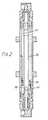
- a viscometer 55 has its inlet connected to the bleed line 49 by a normally closed solenoid valve 57 and its outlet directly connected to the reservoir 1.
- the viscometer 55 includes a stainless steel ball 58 which is movable upwardly and downwardly within an upstanding tube 59 of ground glass. At an upper end of the tube 59 there is a flared portion 61, whilst a seat 63 for the ball 57 is provided near to a lower end of the tube.
- a ball detector coil 65 surrounds a section of the tube 59 immediately above the seat 63.
- the ink make up cartridge 23, referred to above, contains solvents which are added to the ink when a loss of solvents is detected by the viscometer 55. Solvents from the cartridge 23 are supplied to the line between the pump 29 and the gutter 19 via a normally closed make-up solenoid valve 67.
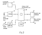
- the control circuit of Figure 3 includes a single chip microcomputer 69 having inputs which are supplied with data representing the current and desired viscosities of ink in the system and outputs which supply control signals for removing any discrepancy between current and desired viscosities.
- a first input to the microcomputer 69 is connected to a cartridge memory device 71 which stores data relating to various kinds of ink and the viscosities thereof for optimum printing results.
- a second input to the microcomputer is connected to a sensor 73, whose input is connected to the ball detector coil 65, referred to above. Further inputs are connected to a temperature sensor 75 and associated analogue/digital converter 77 and to a timer 79.
- Outputs from the microcomputer 69 are connected to the make-up solenoid valve 67 and to the solenoid valve 57, respectively.
- the microcomputer 69 is programmed to activate the viscometer 55, to interpret data relating to viscosity and associated parameters applied to the inputs thereof, and to provide control signals for actuating the make-up solenoid valve 67, as hereinafter described.
- the solenoid valves 57 and 67 are normally closed and the jet run solenoid valve 37 is normally open. Initially the bleed solenoid valve 45 is also open.
- ink from the reservoir 1 is pumped to the container 5 in the head 3 via the filter damper 33, the pressure regulator 35 and the jet run solenoid valve 37.
- the pressure applied to ink within the container 5 forces a jet of ink downwardly via the orifice 9 to the gutter 19.
- a mixture of ink and air is returned to the reservoir 1 via the bleed outlet 11 of the container 5, the bleed line 43 and the bleed solenoid valve 45.
- the bleed solenoid valve 45 is closed.
- Printing can now be commenced by energising the piezoelectric transducer so that the vibrator 13 causes the jet of ink from the orifice 7 to be broken up into droplets of uniform size.and by energising the charging electrode 15 and the deflecting electrodes 17.
- ink at an initial pressure of 6,895 Newtons/sq. metre (1 p.s.i.) is supplied from the outlet of the pump 27 to the inlet to the pump 29 via the pressure relief valve 41, the bleed line 49 and the bleed control orifice 51.
- This supply of ink seals internal clearances within the pump 29. Accordingly, the efficiency of the pump 29 as an air pump is increased, a higher suction is applied to the gutter 19, and a mixture of air and unused liquid is drawn from the gutter.
- the orifice 51 is pre-set to allow a predetermined flow of ink along the bleed line 49, this predetermined flow being sufficient to ensure that the pump 29 is adequately lubricated.
- the microcomputer 69 initiates a check on the viscosity of ink in the system.
- a signal from the microcomputer 69 is applied to the solenoid valve 57, causing the valve to open and to allow ink to flow from the bleed line 49 to the viscometer 55.
- Ink flows upwardly through the tube 59 of the viscometer 55, forcing the steel ball 58 upwardly into the flared portion 61 at the top of the tube.
- the ball remains in the flared portion 61, supported by the upwards flow of ink whilst ink continues to flow upwardly past the ball and then outwardly from the tube 59 to the reservoir 1.
- the presence of the flared portion 61 means there is sufficient space for any solid particles in the ink to pass between the wall of the tube 59 and to return to the reservoir 1.
- the microcomputer 69 activates the timer 79 and at the same time applies a further signal to the valve 57, causing the valve to close.
- the ball 58 descends slowly within the tube 59 at a rate dependent upon the viscosity of ink in the tube.
- the ball detector coil 65 Movement of the ball 58 through the coil 65 is sensed by the sensor 73, which applies an input signal to the microcomputer 69.
- a computation of the viscosity of the ink is made from data representing the time between the closing of solenoid valve 57 and the arrival of the ball 58 at the coil 65, data representing the ambient temperature or the temperature of the ink, supplied by the temperature sensor 75 and the analogue digital converter 77, and data stored in the memory device 71 and representing the relationship between the viscosity of the ink, the time taken for the ball to descend through the tube 59 and the ambient temperature.
- a comparison is then made between the computed viscosity and data representing the optimum viscosity, also stored in the memory device 71.
- an output signal is applied from the microcomputer 69 to the solenoid valve 67.
- the valve 67 is then opened for a predetermined interval of time and a predetermined volume of solvents flows from the make-up cartridge 23 to the line connecting the pump 29 to the gutter 19.
- a similar computation of viscosity is made at intervals of 15 minutes. Each time there is a discrepancy between the computed and optimum viscosities, a fresh volume of solvents is supplied from the make-up cartridge 23. If the computed viscosity equals the optimum viscosity, the solenoid valve 67 remains closed so that no solvents are added.
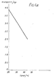
- Coates Black MEK One ink suitable for use in the ink jet printer of Figures 1 to 3 is known as "Coates Black MEK”.
- this ink has a viscosity which varies linearly with temperature between 20°C and 45°C, the viscosity falling from approximately 3.8 c.p. at a temperature of 20°C to approximately 2.0 cp at 45°C.
- the viscosity of this ink and the time taken for the ball to fall through the predetermined distance within the tube 59 of the viscometer 59, as shown in the graph forming Figure 4B.
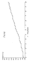
- the printer of Figures 1 to 3 was first operated over a period of 12 hours with the microcomputer 69 disconnected from the solenoid valve 57. This meant that the valve 57 remained closed so that there was no checking of the viscosity of ink in the system and no supply of fresh solvents from the make-up cartridge 23. As shown in Figure 4C, the viscosity increased at a fairly constant rate throughout the 12 hour period, starting at approximately 3.85 c.p. and ending at approximately 4.65 c.p.
- the ambient temperature was 28°C and the time for the ball to fall through the predetermined distance, assuming the viscosity was at its optimum value, was 72 secs. In practice, the measured time of descent was 74 secs. Accordingly, a charge of 8 ccs of solvent was added to the ink after the first check by the control means. This reduced the viscosity by 0.04 c.p. and reduced the ball descent time to 73 secs, as measured at the next check.
Landscapes
- Ink Jet (AREA)
Claims (7)
Applications Claiming Priority (2)
| Application Number | Priority Date | Filing Date | Title |
|---|---|---|---|
| GB838327999A GB8327999D0 (en) | 1983-10-19 | 1983-10-19 | Hydraulic systems |
| GB8327999 | 1983-10-19 |
Publications (2)
| Publication Number | Publication Date |
|---|---|
| EP0142265A1 EP0142265A1 (de) | 1985-05-22 |
| EP0142265B1 true EP0142265B1 (de) | 1988-09-21 |
Family
ID=10550452
Family Applications (1)
| Application Number | Title | Priority Date | Filing Date |
|---|---|---|---|
| EP84306916A Expired EP0142265B1 (de) | 1983-10-19 | 1984-10-10 | Hydraulische Systeme für Tintenstrahldrucker |
Country Status (3)
| Country | Link |
|---|---|
| EP (1) | EP0142265B1 (de) |
| DE (2) | DE3474124D1 (de) |
| GB (1) | GB8327999D0 (de) |
Families Citing this family (3)
| Publication number | Priority date | Publication date | Assignee | Title |
|---|---|---|---|---|
| ATE82196T1 (de) * | 1987-03-13 | 1992-11-15 | Jan Slomianny | Tintensystem fuer tintenstrahlmatrixdrucker. |
| US5455611A (en) * | 1992-05-29 | 1995-10-03 | Scitex Digital Printing, Inc. | Four inch print head assembly |
| FR3025454B1 (fr) | 2014-09-04 | 2016-12-23 | Markem-Imaje Holding | Procede de gestion de la qualite de l'encre d'une imprimante a jet d'encre en fonction de la temperature. |
Citations (2)
| Publication number | Priority date | Publication date | Assignee | Title |
|---|---|---|---|---|
| US4027516A (en) * | 1976-03-16 | 1977-06-07 | Gam Rad, Inc. | Viscometer system |
| EP0046589A1 (de) * | 1980-08-23 | 1982-03-03 | Ernst Thöne | Vorrichtung zum Bestimmen der Viskosität einer Flüssigkeit |
Family Cites Families (2)
| Publication number | Priority date | Publication date | Assignee | Title |
|---|---|---|---|---|
| JPS56136381A (en) * | 1980-03-28 | 1981-10-24 | Sharp Corp | Control of viscosity of jet ink |
| JPS5714053A (en) * | 1980-06-30 | 1982-01-25 | Sharp Corp | Detecting apparatus for abnormally directed jet in ink jet printer |
-
1983
- 1983-10-19 GB GB838327999A patent/GB8327999D0/en active Pending
-
1984
- 1984-10-10 DE DE8484306916T patent/DE3474124D1/de not_active Expired
- 1984-10-10 DE DE1984306916 patent/DE142265T1/de active Pending
- 1984-10-10 EP EP84306916A patent/EP0142265B1/de not_active Expired
Patent Citations (2)
| Publication number | Priority date | Publication date | Assignee | Title |
|---|---|---|---|---|
| US4027516A (en) * | 1976-03-16 | 1977-06-07 | Gam Rad, Inc. | Viscometer system |
| EP0046589A1 (de) * | 1980-08-23 | 1982-03-03 | Ernst Thöne | Vorrichtung zum Bestimmen der Viskosität einer Flüssigkeit |
Also Published As
| Publication number | Publication date |
|---|---|
| DE3474124D1 (en) | 1988-10-27 |
| EP0142265A1 (de) | 1985-05-22 |
| GB8327999D0 (en) | 1983-11-23 |
| DE142265T1 (de) | 1986-02-27 |
Similar Documents
| Publication | Publication Date | Title |
|---|---|---|
| US4658268A (en) | Hydraulic system for recirculating liquid | |
| EP0170449B1 (de) | Steuersystem für die Tintentropfengeschwindigkeit | |
| US4714931A (en) | Ink jet printing system | |
| CN102753351B (zh) | 连续喷墨打印机的流体回路中的测量系统、相关的流体回路和设计为执行所述测量系统的模块 | |
| US5320250A (en) | Method for rapid dispensing of minute quantities of viscous material | |
| US3761953A (en) | Ink supply system for a jet ink printer | |
| US4862192A (en) | Ink system for ink jet matrix printer | |
| US4284210A (en) | Static metering pump | |
| US6010032A (en) | Continuous dispensing system for liquids | |
| CN102770274A (zh) | 用于确定连续喷墨印刷机的耗材流体中的自治的系统 | |
| EP1250956B1 (de) | Verfahren zum kontrollierten Dosieren von Flüssigkeiten unter Verdrängung eines Gaspolsters | |
| CN101497263B (zh) | 喷墨记录装置 | |
| US20030000773A1 (en) | Additive nebulising device | |
| JPH07186404A (ja) | 熱インクジェット・プリンタ用のインク滴体積のテスト方法 | |
| JPH026143A (ja) | ドロップマーキング装置用インク組成制御器と制御方法 | |
| US4575735A (en) | Droplet depositing viscosity line-pressure sensing control for fluid re-supply | |
| EP0891258B1 (de) | Tintenstrahldrucksystem | |
| US4856322A (en) | Method and device for measuring the viscosity of an ink | |
| US4677845A (en) | Device for detecting viscosity of liquid | |
| EP0142265B1 (de) | Hydraulische Systeme für Tintenstrahldrucker | |
| EP0885659A1 (de) | System zur kontinuierlichen Abgabe von Flüsssigkeiten | |
| CN216900072U (zh) | 喷码机粘度检测装置 | |
| US5517216A (en) | Ink jet printer employing time of flight control system for ink jet printers | |
| US5404920A (en) | Automated fluid charging apparatus | |
| RU2051332C1 (ru) | Электрокаплеструйное маркирующее устройство |
Legal Events
| Date | Code | Title | Description |
|---|---|---|---|
| PUAI | Public reference made under article 153(3) epc to a published international application that has entered the european phase |
Free format text: ORIGINAL CODE: 0009012 |
|
| AK | Designated contracting states |
Designated state(s): DE FR GB |
|
| EL | Fr: translation of claims filed | ||
| 17P | Request for examination filed |
Effective date: 19851025 |
|
| DET | De: translation of patent claims | ||
| 17Q | First examination report despatched |
Effective date: 19861112 |
|
| GRAA | (expected) grant |
Free format text: ORIGINAL CODE: 0009210 |
|
| RAP1 | Party data changed (applicant data changed or rights of an application transferred) |
Owner name: DOMINO AMJET, INC. Owner name: DOMINO PRINTING SCIENCES LIMITED |
|
| RAP1 | Party data changed (applicant data changed or rights of an application transferred) |
Owner name: DOMINO AMJET, INC. Owner name: DOMINO PRINTING SCIENCES PLC |
|
| AK | Designated contracting states |
Kind code of ref document: B1 Designated state(s): DE FR GB |
|
| REF | Corresponds to: |
Ref document number: 3474124 Country of ref document: DE Date of ref document: 19881027 |
|
| ET | Fr: translation filed | ||
| PLBE | No opposition filed within time limit |
Free format text: ORIGINAL CODE: 0009261 |
|
| STAA | Information on the status of an ep patent application or granted ep patent |
Free format text: STATUS: NO OPPOSITION FILED WITHIN TIME LIMIT |
|
| 26N | No opposition filed | ||
| PGFP | Annual fee paid to national office [announced via postgrant information from national office to epo] |
Ref country code: DE Payment date: 19941010 Year of fee payment: 11 |
|
| PGFP | Annual fee paid to national office [announced via postgrant information from national office to epo] |
Ref country code: FR Payment date: 19941011 Year of fee payment: 11 |
|
| PG25 | Lapsed in a contracting state [announced via postgrant information from national office to epo] |
Ref country code: FR Effective date: 19960628 |
|
| PG25 | Lapsed in a contracting state [announced via postgrant information from national office to epo] |
Ref country code: DE Effective date: 19960702 |
|
| REG | Reference to a national code |
Ref country code: FR Ref legal event code: ST |
|
| PGFP | Annual fee paid to national office [announced via postgrant information from national office to epo] |
Ref country code: GB Payment date: 19971001 Year of fee payment: 14 |
|
| PG25 | Lapsed in a contracting state [announced via postgrant information from national office to epo] |
Ref country code: GB Free format text: LAPSE BECAUSE OF NON-PAYMENT OF DUE FEES Effective date: 19981010 |
|
| GBPC | Gb: european patent ceased through non-payment of renewal fee |
Effective date: 19981010 |