EP0168178B1 - Processes for finishing guide rollers - Google Patents
Processes for finishing guide rollers Download PDFInfo
- Publication number
- EP0168178B1 EP0168178B1 EP85304176A EP85304176A EP0168178B1 EP 0168178 B1 EP0168178 B1 EP 0168178B1 EP 85304176 A EP85304176 A EP 85304176A EP 85304176 A EP85304176 A EP 85304176A EP 0168178 B1 EP0168178 B1 EP 0168178B1
- Authority
- EP
- European Patent Office
- Prior art keywords
- guide roller
- assembly
- shaft
- roller sleeve
- sleeve
- Prior art date
- Legal status (The legal status is an assumption and is not a legal conclusion. Google has not performed a legal analysis and makes no representation as to the accuracy of the status listed.)
- Expired - Lifetime
Links
Images
Classifications
-
- B—PERFORMING OPERATIONS; TRANSPORTING
- B23—MACHINE TOOLS; METAL-WORKING NOT OTHERWISE PROVIDED FOR
- B23B—TURNING; BORING
- B23B5/00—Turning-machines or devices specially adapted for particular work; Accessories specially adapted therefor
-
- B—PERFORMING OPERATIONS; TRANSPORTING
- B23—MACHINE TOOLS; METAL-WORKING NOT OTHERWISE PROVIDED FOR
- B23B—TURNING; BORING
- B23B3/00—General-purpose turning-machines or devices, e.g. centre lathes with feed rod and lead screw; Sets of turning-machines
- B23B3/06—Turning-machines or devices characterised only by the special arrangement of constructional units
-
- B—PERFORMING OPERATIONS; TRANSPORTING
- B23—MACHINE TOOLS; METAL-WORKING NOT OTHERWISE PROVIDED FOR
- B23B—TURNING; BORING
- B23B31/00—Chucks; Expansion mandrels; Adaptations thereof for remote control
- B23B31/02—Chucks
- B23B31/10—Chucks characterised by the retaining or gripping devices or their immediate operating means
- B23B31/117—Retention by friction only, e.g. using springs, resilient sleeves, tapers
- B23B31/1175—Retention by friction only, e.g. using springs, resilient sleeves, tapers using elastomer rings or sleeves
-
- B—PERFORMING OPERATIONS; TRANSPORTING
- B23—MACHINE TOOLS; METAL-WORKING NOT OTHERWISE PROVIDED FOR
- B23F—MAKING GEARS OR TOOTHED RACKS
- B23F3/00—Making gear teeth involving copying operations controlled by templates having a profile which matches that of the required tooth face or part thereof or a copy thereof to a different scale
Definitions
- This invention relates to processes for finishing guide rollers, more particularly, precision guide rollers for video tape recorders (VTRs).
- VTRs video tape recorders
- a guide roller for a VTR comprises a cylindrical guide roller sleeve with annular bearings and an oil-seal inserted into an axial opening through the roller sleeve.
- the bearing is made of a sintered metal impregnated with oil.
- VTR guide rollers Such guide rollers, particularly guide rollers for VTRs and so forth, which will be referred to hereafter as "VTR guide rollers", must be machined to a smooth and very even surface finish.
- US patent specification US-A-3 541 905 discloses a method of cutting a tubular workpiece radially into rings with a rotating cutting tool.
- the workpiece is rotated by a belt and is held in a loop of the belt which extends at least 180° around the workpiece.
- German patent specification DE-C-518 279 discloses an apparatus for holding rings, particularly piston rings, the outer surfaces of which are to be ground by a grinding wheel.
- the piston rings are rotated and pressed against a holding shaft by rollers.
- a process for finishing the outer surface of a guide rollerfor a video tape recorder the guide roller having a central bore for accommodating bearings and/or lubricating elements, the processing being characterised by the steps of:
- Assembling the guide roller assembly prior to surface machining avoids degradation of the finished surface during the assembly process, which is conventionally performed after surfacing the guide roller sleeve. Also, by driving the guide roller assembly to rotate by means of a driving belt, surfacing is made simpler and does not require highly skilled personnel. Furthermore, the guide rollers can be manufactured with a high yield.
- An apparatus for finishing guide rollers includes a support rotatably supporting the guide roller assembly, and a driving belt which drives the guide roller assembly to rotate.
- a cutting tool is mounted opposite the guide roller assembly supported by the support and can be moved towards and away from the guide roller assembly for machining.
- the guide roller 1 comprises a cylindrical guide roller sleeve 1a and stationary bearings 1b.
- the bearings 1b are pressed into the axial through-opening 1d of the guide roller sleeve 1a.
- the bearings 1 b are made of a sintered metal impregnated with oil.
- a roller shaft 2 passes through the bearings 1b and rotatably supports the guide roller sleeve 1a.
- Oil-seals 1c are then inserted into either end of the through-opening 1d.
- the guide roller sleeve 1a, the bearings 1 b, the oil-seals 1 c and the roller shaft 2 constitute a guide roller assembly.
- Figure 3 illustrates the fundamental concepts of the preferred embodiment of a finishing process for guide rollers and according to the invention, by which the guide roller sleeve 1 a can be surfaced with high uniformity.
- the guide roller assembly is driven by a driving belt 3 which passes over the outer surface of the guide roller sleeve 1a.
- the driving belt 3 presses against the outer surface of the guide roller sleeve with a given tension.
- the tension on the driving belt 3 is referred to hereafter as the "belt pressure”.
- a cutting bit 4 opposes the outer surface of the guide roller sleeve 1a and is held against the opposing surface of the guide roller sleeve 1a with a given pressure.
- This section of the outer surface of the guide roller sleeve 1a is referred to hereafter as the “cutting section”, and diametrically opposes the point of contact between the driving belt 3 and the outer surface of the guide roller sleeve 1a.
- the given pressure at which the bit 4 engages the outer surface of the guide roller sleeve 1a is referred to hereafter as the "bit pressure".
- d represents the distance between a point on the inner surface of a bearing 1b to a diametrically opposing point on the outer surface of the guide roller sleeve 1a.
- the diameter of the roller shaft 2 is smaller than the inner diameter of the bearings 1b.
- the roller shaft 2 is supported rigidly at both ends by a suitable supporting means, so that the roller shaft 2 will not move during finishing.
- the guide roller sleeve 1a will be held against the bit 4 at a constant pressure while the distance d remains constant. In this case, the entire outer surface of the guide roller sleeve 1a will be machined evenly by the bit 4.
- surfacing uniformity is influenced by:
- the guide roller sleeve 1a can be very evenly finished.
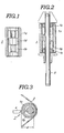
- FIG 4 shows the essential elements of an apparatus for finishing guide rollers.
- the apparatus includes a support shaft 8a extending from a holder 8.
- a eject rod 9 also extends through a hole in the holder 8.
- the holder 8 is stationarily secured to the apparatus so as to define the stationary rotational axis of the guide roller sleeve 1a while the rod 9 is free to move axially.
- a work base 12 opposes the holder 8.
- the work base 12 has an essentially V-shaped top 12a on which the guide roller sleeve 1a with the bearing 1 b is to be mounted in the initial stages of the surfacing operation.
- a push rod 10 and a coaxial boss 11 are movable axially towards and away from the holder 8 independently of each other.
- the push rod 10 rests on the V-shaped top 12a of the work base 12 and is used to push the guide roller sleeve 1 a with the bearings 1 b onto the support shaft 8a extending from the holder 8.
- the boss 11 can pass through a central bore 10a through the push rod 10. At one extreme of travel of the boss 11, an end opening 11a a thereof engages the free end of the support shaft 8a so as stationarily to support the support shaft 8a.
- the driving belt 3 is wound around a driving pulley 7 and upper and lower tension pulleys 5 and 6.
- the pulleys 5, 6 and 7 may be journalled on the apparatus.
- the driving pulley 7 is driven by a drive motor (not shown) through a suitable power transmission mechanism.
- the pulleys 5, 6 and 7 may be mounted on a movable frame (not shown) for movement towards and away from the guide roller sleeve 1 a mounted on the support shaft 8a.
- the bit 4 is adjustably mounted on the apparatus for movement along the x, y and z-axes.
- the x-axis of the bit 4 represents the direction of feed of the bit 4 relative to the guide roller sleeve 1a during machining.
- the y-position of the bit 4 determines the cutting depth during machining.
- the z-position adjustment may be necessary for height adjustment.
- the bearings 1b are pressed into the guide roller sleeve 1a.
- the guide roller sleeve 1a is mounted in the working section of the apparatus in a multistep process.
- the guide roller pre-assembly is placed on the work base 12 such that the through-opening 1d is in alignment with the support shaft 8a.
- the push rod 10 is moved towards the holder 8 so as to drive the support shaft 8a through the through-opening 1d of the guide roller sleeve 1a.
- the boss 11 is inserted through the central bore 10a of the push rod 10 so as to engage the free end of the support shaft 8a.
- the upper and lower tension rollers 5 and 6 are moved towards the guide roller sleeve 1a to tighten the drive belt 3 into contact with the guide roller sleeve 1a at the contact point at a predetermined pressure.
- the driving pulley 7 is driven by the motor in the direction shown by the arrow in Figure 4.
- the bit 4 is moved towards the guide roller sleeve 1 a so as to bring the cutting edge into contact with the guide roller sleeve 1a at a predetermined initial cutting section.
- the initial bit position is determined by the desired cutting depth.
- the bit 4 is driven parallel to the longitudinal axis of the guide roller sleeve 1 a at a predetermined speed.
- the apparatus will have a rough finishing bit and a fine finishing bit at different positions along the z-axis.
- the rough finishing bit and the fine finishing bit are brought into contact with the outer surface of the guide roller sleeve 1a in the stated order. It is also possible to arrange the rough finishing bit and the fine finishing bit horizontally so that rough finishing and fine finishing can be performed in a single-step machining operation.
- the tension pulleys 5 and 6 move towards and away from the work section in which the guide roller sleeve 1 a is mounted, it would also be possible to provide stationary tension pulleys and a movable holder 8 and boss 11 for shifting the guide roller sleeve 1a a towards the drive belt 3 after mounting on the apparatus.
- the drive belt 3 is driven after engaging the outer surface of the guide roller sleeve 1a.
- the upper and lower tension pulleys 5 and 6 are moved away to release the drive belt 3 from the outer surface of the finished guide roller sleeve 1a. Then, the ejecting rod 9 is driven into contact with the opposing edge of the guide sleeve 1a and pushes it back onto the work base 12 and off the support shaft 8a. After returning to the work base 12, the finished guide roller sleeve 1a is ejected from the apparatus and the next guide roller sleeve 1a to be finished is supplied.
- the guide roller sleeves 1a may be inserted and ejected by any conventional means which does not adversely affect their surface finish.
- tapered guide rollers can also be surfaced by the process of the present invention.
- the sintered alloy bearings were pressed into a guide roller sleeve 4.55 mm in diameter and 8.1 mm long. From this pre-assembly, a tapered guide roller sleeve with a major diameter of 4.5 mm and a taper angle of thirty minutes was formed.
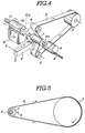
- FIG. 5 shows part of a second machining apparatus applicable to the process according to the invention.
- the tension pulleys of the foregoing first apparatus have been omitted.
- the driving belt 3 is wound around the guide roller sleeve 1a such that the contact point between the outer surface of the guide roller sleeve 1a and the driving belt 3 is on the opposite side from that of the first apparatus.
- the bit 4 again diametrically opposes the contact point.
- roller shaft 2 of Figure 2 it is also possible to use the roller shaft 2 of Figure 2 as the support shaft. In this case, the opposite ends of the roller shaft 2 will be retained by known suitable clamping or restraining means.
Landscapes
- Engineering & Computer Science (AREA)
- Mechanical Engineering (AREA)
- Finish Polishing, Edge Sharpening, And Grinding By Specific Grinding Devices (AREA)
- Turning (AREA)
- Constituent Portions Of Griding Lathes, Driving, Sensing And Control (AREA)
- Electrical Discharge Machining, Electrochemical Machining, And Combined Machining (AREA)
- Bearings For Parts Moving Linearly (AREA)
- Devices For Conveying Motion By Means Of Endless Flexible Members (AREA)
Priority Applications (1)
| Application Number | Priority Date | Filing Date | Title |
|---|---|---|---|
| AT85304176T ATE51176T1 (de) | 1984-06-14 | 1985-06-12 | Verfahren zur fertigbearbeitung von fuehrungsrollen. |
Applications Claiming Priority (2)
| Application Number | Priority Date | Filing Date | Title |
|---|---|---|---|
| JP122704/84 | 1984-06-14 | ||
| JP59122704A JPS614601A (ja) | 1984-06-14 | 1984-06-14 | ベルト駆動によるガイドロ−ラ−の加工方法 |
Publications (2)
| Publication Number | Publication Date |
|---|---|
| EP0168178A1 EP0168178A1 (en) | 1986-01-15 |
| EP0168178B1 true EP0168178B1 (en) | 1990-03-21 |
Family
ID=14842543
Family Applications (1)
| Application Number | Title | Priority Date | Filing Date |
|---|---|---|---|
| EP85304176A Expired - Lifetime EP0168178B1 (en) | 1984-06-14 | 1985-06-12 | Processes for finishing guide rollers |
Country Status (5)
| Country | Link |
|---|---|
| EP (1) | EP0168178B1 (ja) |
| JP (1) | JPS614601A (ja) |
| KR (1) | KR920008743B1 (ja) |
| AT (1) | ATE51176T1 (ja) |
| DE (1) | DE3576661D1 (ja) |
Families Citing this family (2)
| Publication number | Priority date | Publication date | Assignee | Title |
|---|---|---|---|---|
| RU2288076C2 (ru) * | 2004-03-26 | 2006-11-27 | Открытое Акционерное Общество "Корпорация Всмпо-Ависма" | Способ механической обработки труб и устройство для его осуществления |
| DE102010012612B3 (de) * | 2010-03-24 | 2011-06-01 | Wafios Ag | Transportvorrichtung zum Überführen vereinzelter länglicher Werkstücke |
Family Cites Families (6)
| Publication number | Priority date | Publication date | Assignee | Title |
|---|---|---|---|---|
| US1454684A (en) * | 1922-04-04 | 1923-05-08 | James H Matheson | Ball-placing device for tube mills |
| CH103924A (fr) * | 1923-03-03 | 1924-03-17 | Pollens Michel | Procédé pour arrondir des contre-pivots. |
| DE518279C (de) * | 1929-11-06 | 1931-02-24 | Muskegon Piston Ring Co Inc | Vorrichtung zum spitzenlosen Schleifen der aeusseren Flaechen von Ringen, insonderheit Kolbenringen |
| US3451172A (en) * | 1966-09-12 | 1969-06-24 | Ferro Equipment Co | Centerless grinder workpiece ejector |
| DE1627160C3 (de) * | 1967-07-14 | 1974-06-20 | Contec Gmbh, Sursee (Schweiz) | Vorrichtung zum Zerschneiden von ring- oder büchsenförmigen Werkstücken. Annl: Contec GmbH, Sursee (Schweiz) |
| CH1055067A4 (ja) * | 1967-07-25 | 1969-11-14 |
-
1984
- 1984-06-14 JP JP59122704A patent/JPS614601A/ja active Granted
-
1985
- 1985-06-08 KR KR1019850004023A patent/KR920008743B1/ko not_active Expired
- 1985-06-12 EP EP85304176A patent/EP0168178B1/en not_active Expired - Lifetime
- 1985-06-12 AT AT85304176T patent/ATE51176T1/de active
- 1985-06-12 DE DE8585304176T patent/DE3576661D1/de not_active Expired - Lifetime
Also Published As
| Publication number | Publication date |
|---|---|
| KR860000114A (ko) | 1986-01-25 |
| EP0168178A1 (en) | 1986-01-15 |
| JPH0438521B2 (ja) | 1992-06-24 |
| DE3576661D1 (de) | 1990-04-26 |
| JPS614601A (ja) | 1986-01-10 |
| ATE51176T1 (de) | 1990-04-15 |
| KR920008743B1 (ko) | 1992-10-09 |
Similar Documents
| Publication | Publication Date | Title |
|---|---|---|
| JP4499224B2 (ja) | 機械加工方法および機械加工装置 | |
| KR20010049775A (ko) | 크랭크축 저어널을 가공하는 장치 및 방법 | |
| US4617714A (en) | Process and apparatus for finishing a guide roller | |
| EP0168178B1 (en) | Processes for finishing guide rollers | |
| KR950008007A (ko) | 공작물을 기계가공하도록 회전시키는 장치 및 기계 가공에 의한 제품 형성 방법 | |
| CN109227353B (zh) | 柱形磁芯的端面研磨机 | |
| HU209638B (en) | Method and apparatus for generating machining with abrasive belt | |
| CA1332793C (en) | Method and apparatus for forming an incomplete hole in a workpiece | |
| US3936104A (en) | Bearing assembly for screw machine spindle | |
| CN100431755C (zh) | 车床主轴单元及车床装置 | |
| CN117548696B (zh) | 一种外圈双道止动槽的轴承外套圈的加工工艺及设备 | |
| US6154941A (en) | Crankshaft thrust face burnisher and method | |
| JP4330277B2 (ja) | 回転型ガイドブッシュ | |
| JP3835255B2 (ja) | ギア歯面加工方法及び装置 | |
| US4590827A (en) | Recess tool holder | |
| JPH10193202A (ja) | 心押し台 | |
| JP3415833B2 (ja) | 端面加工機 | |
| JPH06179030A (ja) | 管材用テーパねじ転造機 | |
| JP3827402B2 (ja) | 動圧流体軸受けの溝形成装置 | |
| US4398078A (en) | Finishing of annular articles | |
| JPH0350663B2 (ja) | ||
| JPH07242B2 (ja) | 回転長尺材の送り装置 | |
| CN219945780U (zh) | 旋转夹紧装置 | |
| JP3304617B2 (ja) | Nc自動旋盤のガイドブッシュ調整方法及びその装置 | |
| JP2000107947A (ja) | 円筒面加工装置、軸受内径加工装置及び円筒穴付構造体 |
Legal Events
| Date | Code | Title | Description |
|---|---|---|---|
| PUAI | Public reference made under article 153(3) epc to a published international application that has entered the european phase |
Free format text: ORIGINAL CODE: 0009012 |
|
| AK | Designated contracting states |
Designated state(s): AT DE FR GB NL |
|
| 17P | Request for examination filed |
Effective date: 19860530 |
|
| 17Q | First examination report despatched |
Effective date: 19871208 |
|
| GRAA | (expected) grant |
Free format text: ORIGINAL CODE: 0009210 |
|
| AK | Designated contracting states |
Kind code of ref document: B1 Designated state(s): AT DE FR GB NL |
|
| REF | Corresponds to: |
Ref document number: 51176 Country of ref document: AT Date of ref document: 19900415 Kind code of ref document: T |
|
| REF | Corresponds to: |
Ref document number: 3576661 Country of ref document: DE Date of ref document: 19900426 |
|
| ET | Fr: translation filed | ||
| PLBE | No opposition filed within time limit |
Free format text: ORIGINAL CODE: 0009261 |
|
| STAA | Information on the status of an ep patent application or granted ep patent |
Free format text: STATUS: NO OPPOSITION FILED WITHIN TIME LIMIT |
|
| 26N | No opposition filed | ||
| PGFP | Annual fee paid to national office [announced via postgrant information from national office to epo] |
Ref country code: GB Payment date: 19950601 Year of fee payment: 11 |
|
| PGFP | Annual fee paid to national office [announced via postgrant information from national office to epo] |
Ref country code: DE Payment date: 19950607 Year of fee payment: 11 |
|
| PGFP | Annual fee paid to national office [announced via postgrant information from national office to epo] |
Ref country code: FR Payment date: 19950609 Year of fee payment: 11 |
|
| PGFP | Annual fee paid to national office [announced via postgrant information from national office to epo] |
Ref country code: AT Payment date: 19950627 Year of fee payment: 11 |
|
| PGFP | Annual fee paid to national office [announced via postgrant information from national office to epo] |
Ref country code: NL Payment date: 19950628 Year of fee payment: 11 |
|
| PG25 | Lapsed in a contracting state [announced via postgrant information from national office to epo] |
Ref country code: GB Effective date: 19960612 Ref country code: AT Effective date: 19960612 |
|
| PG25 | Lapsed in a contracting state [announced via postgrant information from national office to epo] |
Ref country code: NL Effective date: 19970101 |
|
| GBPC | Gb: european patent ceased through non-payment of renewal fee |
Effective date: 19960612 |
|
| PG25 | Lapsed in a contracting state [announced via postgrant information from national office to epo] |
Ref country code: FR Effective date: 19970228 |
|
| PG25 | Lapsed in a contracting state [announced via postgrant information from national office to epo] |
Ref country code: DE Effective date: 19970301 |
|
| NLV4 | Nl: lapsed or anulled due to non-payment of the annual fee |
Effective date: 19970101 |
|
| REG | Reference to a national code |
Ref country code: FR Ref legal event code: ST |