EP0166253B1 - Device for accommodating cash enclosing envelopes - Google Patents
Device for accommodating cash enclosing envelopes Download PDFInfo
- Publication number
- EP0166253B1 EP0166253B1 EP85106600A EP85106600A EP0166253B1 EP 0166253 B1 EP0166253 B1 EP 0166253B1 EP 85106600 A EP85106600 A EP 85106600A EP 85106600 A EP85106600 A EP 85106600A EP 0166253 B1 EP0166253 B1 EP 0166253B1
- Authority
- EP
- European Patent Office
- Prior art keywords
- envelope
- cash
- envelopes
- receiving member
- enclosing
- Prior art date
- Legal status (The legal status is an assumption and is not a legal conclusion. Google has not performed a legal analysis and makes no representation as to the accuracy of the status listed.)
- Expired
Links
Images


Classifications
-
- G—PHYSICS
- G07—CHECKING-DEVICES
- G07D—HANDLING OF COINS OR VALUABLE PAPERS, e.g. TESTING, SORTING BY DENOMINATIONS, COUNTING, DISPENSING, CHANGING OR DEPOSITING
- G07D11/00—Devices accepting coins; Devices accepting, dispensing, sorting or counting valuable papers
- G07D11/009—Depositing devices
- G07D11/0096—Accepting paper currency or other valuables in containers, e.g. in code-marked envelopes
-
- B—PERFORMING OPERATIONS; TRANSPORTING
- B65—CONVEYING; PACKING; STORING; HANDLING THIN OR FILAMENTARY MATERIAL
- B65H—HANDLING THIN OR FILAMENTARY MATERIAL, e.g. SHEETS, WEBS, CABLES
- B65H1/00—Supports or magazines for piles from which articles are to be separated
- B65H1/08—Supports or magazines for piles from which articles are to be separated with means for advancing the articles to present the articles to the separating device
- B65H1/18—Supports or magazines for piles from which articles are to be separated with means for advancing the articles to present the articles to the separating device controlled by height of pile
Definitions
- the present invention relates to a device for accomodating cash enclosing envelopes with the features according to the first part of claim 1.
- a device for accomodating cash enclosing envelopes with the features according to the first part of claim 1.
- Such a device is known from US-A-3 873 443.
- the envelope take-in assembly is formed by rotatively driven endless chaines which support the envelopes to be taken into the envelope container from below.
- the means for detecting the quantity of envelopes placed on the receiving member comprises a photocell the light path of which is interrupted by an advanced envelope itself, causing the envelope receiving member to be lowered.
- the object of the present invention is to improve the known envelope accomodating device.
- the envelope pushes up the free end of the arcuate lever of the means for detecting the quantity of cash enclosing envelopes, so that the advancing envelope is pushed down by the counteraction of the lever. Accordingly, even if the envelope is bent or recurved upwardly, this envelope is smoothly and acurately placed in the uppermost position on a stack of envelopes on the receiving member.
- the lever when in the course of being moved upwardly the free end of the lever blocks the optical path of the photosensor a corresponding motor is driven to slightly lower the receiving member. That is, the lever has a double function of detecting the level of the uppermost envelope and of guiding the envelope taken in by the take-in assembly into the uppermost position on the receiving member.
- the means for detecting the quantity of cash enclosing envelopes is advantageously so designed that a function of guiding an envelope into the position where it is to be detected is realized as well.
- the take-in assembly is provided with an upper rotary member contacting the envelopes from above, the envelopes are sandwiched between the upper and lower rotary members so that they are securely and smoothly taken in even when they are deformed or bent.
- the receiving member is controlled to move upward or downward so that the uppermost of the cash enclosing envelopes on the receiving member is at a substantially definite level at all times. Accordingly, the cash enclosing envelope taken into the container through its inlet is allowed to fall under gravity a substantially constant distance at all times, and this distance of fall can be set to a very small value, with the result that the cash enclosing envelopes placed onto the receiving member one after another can be stacked up thereon in an orderly arrangement.
- This results in an improved accommodation efficiency eliminates the likelihood that the cash enclosing envelope will be subjected to an objectionable force that could cause damage to the envelope, and further renders the envelopes easy to handle when they are to be withdrawn from the container.
- the illustrated embodiment of the invention is adapted for use in an enveloped cash depositing machine.
- the depositing machine comprises an envelope handling device 1 for marking a cash enclosing envelope E with receipt data when the envelope E is placed into the device 1 through an inlet 10, and an envelope accommodating device 11 for accommodating the envelope E processed for receipt.
- the envelope handling device 1 comprises a conveyor 2 for transporting the envelope E placed in through the inlet 10 to the accommodating device 11, a printer 4 for printing on the surface of a label receipt data as to the envelope E placed in, a label feeder 3 for supplying to the path of transport of the conveyor 2 labels each having receipt data printed on one surface and an adhesive applied to the other surface, posture adjusting means 6 for aligning the envelope being transported with the path of transport and directing the envelope toward the direction of transport, and a roller 5 for affixing the label to the lower surface of the forwarded envelope.
- the labeled envelope is sent to the accommodating device 11.
- the conveyor 2 comprises an upper belt 8 and a lower belt 9 for transporting the envelope as held therebetween.
- the upper belt 8 is provided on a support assembly 7 which is supported upwardly or downwardly movably.
- the label and the envelope are brought into pressing contact with each other between the upper belt 8 and the roller 5, whereby the label is affixed to the lower surface of the envelope.
- the envelope accommodating device 11 comprises a container 12 for cash enclosing envelopes.
- the container 12 has an inlet 20 formed at an upper portion on its one side and opposed to the outlet of the envelope handling device 1.
- a receiving plate 13 which is slightly inclined downward toward the inlet 20.
- the plate 13 is guided upward and downward.
- Lift drive means moves the plate 13 upward or downward.
- An assembly 14 for taking in the envelope sent into the inlet 20 is disposed within the container 12 near the inlet 20.
- a sensor lever 15 is pivotably provided above the receiving plate 13.
- the receiving plate 13 When the uppermost of cash enclosing envelopes E on the receiving plate 13 pushes up one end of the sensor lever 15 in contact therewith, the receiving plate 13 is lowered by the lift drive means to a position where the uppermost envelope tends to move out of contact with the sensor lever 15. In this way, the level of the receiving plate 13 is so adjusted that the uppermost of the cash enclosing envelopes on the receiving plate 13 will be held at a substantially definite level at all times.
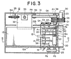
- Figs. 2 and 3 show the envelope accommodating device 11 in greater detail.
- the container 12 is internally provided with partitions 12A and 12B for defining a space for accommodating envelopes.
- the envelope taking-in assembly 14 includes rotary shafts 16, 17 and 18 rotatably supported by and extending between the partitions 12A and 12B.
- the rotary shaft 16 has two pulleys P1 and a pair of pivotal plates 19 disposed on opposite sides of each pulley P1 and each pivotably attached at its one end to the shaft 16.
- a rotary shaft 19a is provided between the other ends of the pair of pivotal plates 19 and carries a pulley P2.
- An endless belt 22 is reeved around the pulleys P1 and P2.
- Two rollers 21 are fixedly mounted on the rotary shaft 18.
- the pulleys P2 supported by the pivotal plates 19 bear on the rollers 21.
- a taking-in drive motor 23 is attached to a lower portion of the container 12 outside thereof and has an output shaft carrying a spur gear G1.
- a rotary shaft 26 mounted on a lower portion of the partition 12B and projecting outside the envelope accommodating space is provided with a pulley P3 and a spur gear G2.
- the spur gears G1 and G2 are in mesh with each other.
- the rotary shaft 18 extends outward beyond the partitions 12A and 12B, and pulleys P5 and P4 are fixedly mounted on the shaft ends.
- a belt 24 is reeved around the pulleys P4 and P5.
- Opposite ends of the rotary shaft 17, similarly extending outward beyond the partitions 12A and 128, are provided with a pulley P6 and a spur gear G3, respectively.
- a belt 25 is reeved around the pulleys P6 and P5.
- One end of the rotary shaft 16 extends outward beyond the partition 12B and fixedly carries a spur gear G4 mesh
- the rollers 21 and the pulleys P1 rotate in timed relation, further causing the belts 22 to rotate the pulleys P2 in timed relation with but in opposite direction to the rollers 21, whereby the envelope E placed between the pulleys P2 and the rollers 21 is taken in. Since the pivotal plates 19 are movable about the rotary shaft 16, the pulleys P2 are pushed up by the inserted envelope E by an amount corresponding to the thickness of the envelope E.
- An upright post 33 is provided inside the container 12 at one side thereof and extends through a bore formed in a lift block 32, which in turn is movable on the post 33 upward and downward.
- a portion of the lift block 32 is projected into the envelope accommodating space through a ver- tially elongated cutout formed in the partition 12B, and the receiving plate 13 is fixed to the projecting portion.
- a tension spring 34 is secured at its one end to the lift block 32.
- the tension spring 34 is passed over a pulley 34 rotatably supported by an upper portion of the container 12 and extends downward.
- the other end of the spring 34 is fixed to the bottom of the container 12.
- a lift drive motor 30, mounted on a lower portion of the container 12 outside thereof, has an output shaft fixedly carrying a spur gear G5.
- Two lower rotary shafts 38, 40 and an upper rotary shaft 39 disposed within the container 12 outside the partition 12B are attached to a side wall of the container 12.
- the rotary shafts 39 and 40 are so arranged that a line through these shafts 39 and 40 is vertical.
- the shaft 38 fixedly carries a gear G6 meshing with the gear G5 and a pulley P7.
- the shafts 39 and 40 are provided with pulleys P8 and P9, respectively.
- a belt 31, which is preferably a timing belt, is reeved around the pulleys P7, P8 and P9. Between the pulleys P8 and P9, a portion of the belt 31 is fixed to the lift block 32.
- the motor 30 is provided with a brake.
- the lever 15 is arcuate, and the bulging side thereof is oriented downward or toward the inelt 20.
- the lever 15 is pivotably supported at its one end by a rod 36 extending between and fixed to the partitions 12A and 12B.
- a photosensor 37 is provided, such that the optical path thereof is blocked by the lever 15 when the other end, i.e. acting end, of the lever 15 is raised approximately to the level of the rod 36.
- the lever 15 and the photosensor 37 constitute means for detecting the quantity of cash enclosing envelopes on the receiving plate 13.
- the distance the taken-in envelope falls under gravity is so small that envelopes are orderly stacked up on the receiving plate 13. If the envelope taken in has a large thickness, the acting end of the lever 15 still remains to block the optical path of the photosensor 37 even when the receiving plate lowers slightly. Consequently, the receiving plate 13 is lowered until the optical path becomes no longer blocked.
- the plate 13 strikes against a pin 42 on the free end of a lever 41 which is pivotably supported and retained in a suitable posture by a spring, pushing down the lever end against the action of the spring to cause an intermediate member to actuate a near fullness detecting switch 43.
- the detection signal of the switch 43 turns on a near fullness display lamp (not shown).
- fullness detecting means Disposed further below the near fullness detecting means is fullness detecting means which comprises a lever 51 having a pin 52, and a switch 53.
- a fullness detection signal is produced to turn on a fullness display lamp and give an alarm.
- shutters (not shown) provided for the inlets 10 and 20 are closed to automatically discontinue processing for cash enclosing envelopes.
Landscapes
- Engineering & Computer Science (AREA)
- Mechanical Engineering (AREA)
- Physics & Mathematics (AREA)
- General Physics & Mathematics (AREA)
- Container Filling Or Packaging Operations (AREA)
- Supplying Of Containers To The Packaging Station (AREA)
- Control Of Vending Devices And Auxiliary Devices For Vending Devices (AREA)
- Pile Receivers (AREA)
- Sheets, Magazines, And Separation Thereof (AREA)
- Packaging Of Special Articles (AREA)
Priority Applications (1)
| Application Number | Priority Date | Filing Date | Title |
|---|---|---|---|
| AT85106600T ATE47496T1 (de) | 1984-05-31 | 1985-05-29 | Vorrichtung zum unterbringen von geld enthaltenden umschlaegen. |
Applications Claiming Priority (2)
| Application Number | Priority Date | Filing Date | Title |
|---|---|---|---|
| JP112764/84 | 1984-05-31 | ||
| JP59112764A JPS60258057A (ja) | 1984-05-31 | 1984-05-31 | 紙葉類収納装置 |
Publications (3)
| Publication Number | Publication Date |
|---|---|
| EP0166253A2 EP0166253A2 (en) | 1986-01-02 |
| EP0166253A3 EP0166253A3 (en) | 1987-11-04 |
| EP0166253B1 true EP0166253B1 (en) | 1989-10-18 |
Family
ID=14594931
Family Applications (1)
| Application Number | Title | Priority Date | Filing Date |
|---|---|---|---|
| EP85106600A Expired EP0166253B1 (en) | 1984-05-31 | 1985-05-29 | Device for accommodating cash enclosing envelopes |
Country Status (5)
| Country | Link |
|---|---|
| US (1) | US4838480A (ja) |
| EP (1) | EP0166253B1 (ja) |
| JP (1) | JPS60258057A (ja) |
| AT (1) | ATE47496T1 (ja) |
| DE (1) | DE3573851D1 (ja) |
Families Citing this family (14)
| Publication number | Priority date | Publication date | Assignee | Title |
|---|---|---|---|---|
| US4597330A (en) * | 1984-11-28 | 1986-07-01 | Diebold, Incorporated | Depository envelope printing mechanism |
| GB8915048D0 (en) * | 1989-06-30 | 1989-08-23 | Ncr Co | Container for holding a stack of articles |
| GB8915126D0 (en) * | 1989-06-30 | 1989-08-23 | Ncr Co | Apparatus for stacking articles in a container |
| GB8927225D0 (en) * | 1989-12-01 | 1990-01-31 | Ncr Co | Depository apparatus for envelopes and single sheets |
| US5017972A (en) * | 1990-05-30 | 1991-05-21 | Xerox Corporation | Elevator tray position control apparatus |
| US5422467A (en) * | 1993-01-15 | 1995-06-06 | Interbold | Article depositing apparatus |
| US5722332A (en) * | 1995-12-28 | 1998-03-03 | M.I.B. Elettronica S.R.L. | Apparatus and process for conducting deposit and drawing operations of banknotes and valuables |
| DE19735563A1 (de) * | 1997-08-11 | 1999-02-18 | Mehring Gmbh | Vorrichtung zum Handhaben von Poststücken mit fristwahrendem Charakter |
| DE19805562C1 (de) * | 1998-02-11 | 1999-04-15 | Siemens Ag | Stapelfach für flache Sendungen |
| US6241099B1 (en) * | 1999-05-12 | 2001-06-05 | Northrop Grumman Corporation | Flats bundle collator |
| US6474548B1 (en) * | 1999-11-30 | 2002-11-05 | Diebold, Incorporated | Deposit accepting and storage apparatus and method for automated banking machine |
| DE10008136A1 (de) * | 2000-02-22 | 2001-08-23 | Giesecke & Devrient Gmbh | Stapler für blattförmige Gegenstände |
| GB2394710B (en) * | 2002-11-02 | 2007-03-14 | Ncr Int Inc | Media storage |
| JP6859745B2 (ja) * | 2017-02-23 | 2021-04-14 | 富士ゼロックス株式会社 | 後処理装置および画像形成装置 |
Family Cites Families (43)
| Publication number | Priority date | Publication date | Assignee | Title |
|---|---|---|---|---|
| GB337688A (en) * | 1930-01-16 | 1930-11-06 | Carl Wilhelm Hartmann | An improved conveyor for cartons |
| GB763013A (en) * | 1954-05-21 | 1956-12-05 | Adams Powel Equipment Ltd | Improvements in and relating to conveying apparatus |
| US2849236A (en) * | 1954-09-14 | 1958-08-26 | Kimberly Clark Co | Revolving layboy piler |
| US3102627A (en) * | 1956-03-29 | 1963-09-03 | Internat Staple And Machine Co | Apparatus for centering cartons |
| US2853725A (en) * | 1956-06-19 | 1958-09-30 | Donnelley & Sons Co | Machine for forming hinge joints in cased books |
| US2923587A (en) * | 1958-02-10 | 1960-02-02 | Bank Of America Nat Trust & Savings Ass | Autoamtic receiving teller |
| US3101892A (en) * | 1960-12-01 | 1963-08-27 | Nat Rejectors Gmbh | Bill-receiving cash boxes |
| US3182994A (en) * | 1962-02-26 | 1965-05-11 | American Can Co | Gauging mechanism |
| US3237365A (en) * | 1962-09-12 | 1966-03-01 | Fmc Corp | Case loading machine |
| US3213733A (en) * | 1964-06-29 | 1965-10-26 | F T Rosback Company | Three knife book trimmer |
| US3334895A (en) * | 1965-04-30 | 1967-08-08 | Curtice F Daniels | Apparatus for stacking sheets of veneer |
| US3540970A (en) * | 1967-12-05 | 1970-11-17 | Claude Raymond Huntwork | Tipping machine |
| US3779367A (en) * | 1970-10-09 | 1973-12-18 | Auto Mat Corp | Cleaning machine |
| GB1373349A (en) * | 1971-01-15 | 1974-11-13 | Mil Ltd | Haul-off machines |
| US3772971A (en) * | 1971-05-27 | 1973-11-20 | Taylor M L | Batch stacker |
| DE2127965A1 (de) * | 1971-06-05 | 1972-12-28 | Kochs Adler Ag, 4800 Bielefeld | Maschine zum erschliessen von Faltkartons mittels Klebestreifen |
| US3873443A (en) * | 1973-01-03 | 1975-03-25 | Docutel Corp | Depository system |
| US4016980A (en) * | 1975-05-09 | 1977-04-12 | Docutronix, Inc. | Device for checking envelopes for enclosed documents |
| JPS528900A (en) * | 1975-07-10 | 1977-01-24 | Tokyo Electric Co Ltd | Note transfer system |
| JPS5211571A (en) * | 1975-07-17 | 1977-01-28 | Fuji Electric Co Ltd | Device of pulling paper sheets |
| US3968364A (en) * | 1975-08-27 | 1976-07-06 | Xerox Corporation | Height sensing device |
| US4085687A (en) * | 1976-01-12 | 1978-04-25 | Diebold, Incorporated | Remote envelope depository construction |
| DE2724980C2 (de) * | 1977-06-02 | 1979-07-19 | Bielomatik Leuze & Co, 7442 Neuffen | Vorrichtung zum Transport von Blattlagen |
| JPS5483275A (en) * | 1977-12-14 | 1979-07-03 | Canon Kk | Paper surface detector |
| US4228994A (en) * | 1979-07-16 | 1980-10-21 | White Consolidated Industries, Inc. | Variable jogger for a sheet feeder |
| JPS5623112A (en) * | 1979-07-31 | 1981-03-04 | Natl House Ind Co Ltd | Locating device |
| US4310160A (en) * | 1979-09-10 | 1982-01-12 | Leo Willette | Card shuffling device |
| US4308804A (en) * | 1979-11-08 | 1982-01-05 | Honeywell Information Systems Inc. | Automatic cash depository |
| US4312277A (en) * | 1980-04-02 | 1982-01-26 | Diebold Incorporated | Remote depository with sealed deposit container construction |
| IT1130118B (it) * | 1980-04-16 | 1986-06-11 | Olivetti & Co Spa | Apparecchiatura di deposito di valori in busta con dispensazione automatica delle buste |
| US4321103A (en) * | 1980-09-25 | 1982-03-23 | Hi-Speed Checkweigher Co., Inc. | Mechanism for applying merchandising labels to packages/objects of different weights and dimensions |
| US4314869A (en) * | 1980-12-24 | 1982-02-09 | Label-Aire | Wine bottle labeler |
| US4386768A (en) * | 1981-02-17 | 1983-06-07 | Harris Corporation | Signature feeding and stitching apparatus |
| JPS5874455A (ja) * | 1981-10-26 | 1983-05-04 | Toshiba Corp | 紙葉類の集積装置 |
| JPS58192168A (ja) * | 1982-05-06 | 1983-11-09 | Toshiba Corp | 自動取引装置 |
| JPS58192167A (ja) * | 1982-05-06 | 1983-11-09 | Toshiba Corp | 自動取引装置 |
| JPS5930186A (ja) * | 1982-08-06 | 1984-02-17 | インタ−ナシヨナル ビジネス マシ−ンズ コ−ポレ−シヨン | 自動預金・支払装置用紙幣収納機構 |
| US4435243A (en) * | 1982-09-24 | 1984-03-06 | Diebold, Incorporated | Deposit information labeling mechanism for ATM envelope depositing equipment |
| JPS5960594A (ja) * | 1982-09-29 | 1984-04-06 | 富士通株式会社 | 紙幣取扱装置 |
| JPS59102755A (ja) * | 1982-12-03 | 1984-06-13 | Canon Inc | シ−ト収積装置 |
| FR2544658B1 (fr) * | 1983-04-22 | 1985-12-20 | Dev Mat Emballage | Intallation pour produire des caisses en carton sous forme pliee |
| US4512263A (en) * | 1983-05-06 | 1985-04-23 | International Business Machines Corporation | Depository apparatus with sequential stacking |
| US4607831A (en) * | 1983-10-19 | 1986-08-26 | Trimmer Machine Co., Inc. | Overlapping signature stream with adjustable side plate jogger |
-
1984
- 1984-05-31 JP JP59112764A patent/JPS60258057A/ja active Pending
-
1985
- 1985-05-29 AT AT85106600T patent/ATE47496T1/de active
- 1985-05-29 EP EP85106600A patent/EP0166253B1/en not_active Expired
- 1985-05-29 DE DE8585106600T patent/DE3573851D1/de not_active Expired
-
1987
- 1987-08-07 US US07/082,997 patent/US4838480A/en not_active Expired - Fee Related
Also Published As
| Publication number | Publication date |
|---|---|
| ATE47496T1 (de) | 1989-11-15 |
| US4838480A (en) | 1989-06-13 |
| EP0166253A3 (en) | 1987-11-04 |
| EP0166253A2 (en) | 1986-01-02 |
| DE3573851D1 (en) | 1989-11-23 |
| JPS60258057A (ja) | 1985-12-19 |
Similar Documents
| Publication | Publication Date | Title |
|---|---|---|
| EP0166253B1 (en) | Device for accommodating cash enclosing envelopes | |
| EP0157801B1 (en) | Card feeding, transfer and output apparatus for an automatic embossing system | |
| US4099609A (en) | Bobbin elevating conveyor and orientor | |
| EP0176662B1 (en) | Stretch film packaging machine | |
| US4531344A (en) | Device for aligning and banding a pile of paper sheets | |
| JPS61131A (ja) | ラベル貼設装置 | |
| GB2237798A (en) | Presenting piles to a sheet separating location | |
| US5188504A (en) | Envelope opener and load separator | |
| EP0164649B1 (en) | Envelope delivery device | |
| US4538330A (en) | Venetian blind assembly apparatus | |
| JPS6144787B2 (ja) | ||
| SU668822A1 (ru) | Устройство дл транспортировки книжных блоков и укладки их в два штабел | |
| EP0160280A2 (en) | Method and apparatus for supplying bar-like members | |
| JP2673723B2 (ja) | 紙葉類の堆積装置 | |
| KR100239772B1 (ko) | 지로(giro)용지 처리장치 | |
| JPH07223399A (ja) | 台紙にカードをセットし、それを封筒に挿入する装置 | |
| JP3030922B2 (ja) | 凝集パターン判定用プレート移送装置 | |
| JP2001269625A (ja) | 仕分け装置 | |
| JPH09106469A (ja) | 棒金搬送装置 | |
| KR960005293B1 (ko) | 자동판매기의 상품반송장치 | |
| ITFI970040A1 (it) | Cassetta postale automatizzata | |
| CA1329342C (en) | Envelope opener and load separator | |
| JPH0234859B2 (ja) | Shiitobunruisochi | |
| JPS6156142B2 (ja) | ||
| JP3397745B2 (ja) | 紙葉類整位搬送装置 |
Legal Events
| Date | Code | Title | Description |
|---|---|---|---|
| PUAI | Public reference made under article 153(3) epc to a published international application that has entered the european phase |
Free format text: ORIGINAL CODE: 0009012 |
|
| 17P | Request for examination filed |
Effective date: 19850529 |
|
| AK | Designated contracting states |
Designated state(s): AT BE CH DE FR GB IT LI LU NL SE |
|
| PUAL | Search report despatched |
Free format text: ORIGINAL CODE: 0009013 |
|
| AK | Designated contracting states |
Kind code of ref document: A3 Designated state(s): AT BE CH DE FR GB IT LI LU NL SE |
|
| 17Q | First examination report despatched |
Effective date: 19880128 |
|
| GRAA | (expected) grant |
Free format text: ORIGINAL CODE: 0009210 |
|
| AK | Designated contracting states |
Kind code of ref document: B1 Designated state(s): AT BE CH DE FR GB IT LI LU NL SE |
|
| PG25 | Lapsed in a contracting state [announced via postgrant information from national office to epo] |
Ref country code: NL Effective date: 19891018 Ref country code: LI Effective date: 19891018 Ref country code: IT Free format text: LAPSE BECAUSE OF FAILURE TO SUBMIT A TRANSLATION OF THE DESCRIPTION OR TO PAY THE FEE WITHIN THE PRESCRIBED TIME-LIMIT;WARNING: LAPSES OF ITALIAN PATENTS WITH EFFECTIVE DATE BEFORE 2007 MAY HAVE OCCURRED AT ANY TIME BEFORE 2007. THE CORRECT EFFECTIVE DATE MAY BE DIFFERENT FROM THE ONE RECORDED. Effective date: 19891018 Ref country code: FR Free format text: THE PATENT HAS BEEN ANNULLED BY A DECISION OF A NATIONAL AUTHORITY Effective date: 19891018 Ref country code: CH Effective date: 19891018 Ref country code: BE Effective date: 19891018 Ref country code: AT Effective date: 19891018 |
|
| REF | Corresponds to: |
Ref document number: 47496 Country of ref document: AT Date of ref document: 19891115 Kind code of ref document: T |
|
| REF | Corresponds to: |
Ref document number: 3573851 Country of ref document: DE Date of ref document: 19891123 |
|
| REG | Reference to a national code |
Ref country code: CH Ref legal event code: PL |
|
| EN | Fr: translation not filed | ||
| NLV1 | Nl: lapsed or annulled due to failure to fulfill the requirements of art. 29p and 29m of the patents act | ||
| PGFP | Annual fee paid to national office [announced via postgrant information from national office to epo] |
Ref country code: SE Payment date: 19900517 Year of fee payment: 6 |
|
| PG25 | Lapsed in a contracting state [announced via postgrant information from national office to epo] |
Ref country code: GB Effective date: 19900529 |
|
| PG25 | Lapsed in a contracting state [announced via postgrant information from national office to epo] |
Ref country code: LU Free format text: LAPSE BECAUSE OF NON-PAYMENT OF DUE FEES Effective date: 19900531 |
|
| PGFP | Annual fee paid to national office [announced via postgrant information from national office to epo] |
Ref country code: DE Payment date: 19900531 Year of fee payment: 6 |
|
| PLBE | No opposition filed within time limit |
Free format text: ORIGINAL CODE: 0009261 |
|
| STAA | Information on the status of an ep patent application or granted ep patent |
Free format text: STATUS: NO OPPOSITION FILED WITHIN TIME LIMIT |
|
| 26N | No opposition filed | ||
| GBPC | Gb: european patent ceased through non-payment of renewal fee | ||
| PG25 | Lapsed in a contracting state [announced via postgrant information from national office to epo] |
Ref country code: SE Effective date: 19910530 |
|
| PG25 | Lapsed in a contracting state [announced via postgrant information from national office to epo] |
Ref country code: DE Effective date: 19920303 |
|
| EUG | Se: european patent has lapsed |
Ref document number: 85106600.1 Effective date: 19911209 |