EP0165188A2 - Method and device for manufacturing regular ply yarns - Google Patents
Method and device for manufacturing regular ply yarns Download PDFInfo
- Publication number
- EP0165188A2 EP0165188A2 EP85420105A EP85420105A EP0165188A2 EP 0165188 A2 EP0165188 A2 EP 0165188A2 EP 85420105 A EP85420105 A EP 85420105A EP 85420105 A EP85420105 A EP 85420105A EP 0165188 A2 EP0165188 A2 EP 0165188A2
- Authority
- EP
- European Patent Office
- Prior art keywords
- wire
- passing
- wires
- spindle
- pulleys
- Prior art date
- Legal status (The legal status is an assumption and is not a legal conclusion. Google has not performed a legal analysis and makes no representation as to the accuracy of the status listed.)
- Withdrawn
Links
Images
Classifications
-
- D—TEXTILES; PAPER
- D02—YARNS; MECHANICAL FINISHING OF YARNS OR ROPES; WARPING OR BEAMING
- D02G—CRIMPING OR CURLING FIBRES, FILAMENTS, THREADS, OR YARNS; YARNS OR THREADS
- D02G3/00—Yarns or threads, e.g. fancy yarns; Processes or apparatus for the production thereof, not otherwise provided for
- D02G3/22—Yarns or threads characterised by constructional features, e.g. blending, filament/fibre
- D02G3/26—Yarns or threads characterised by constructional features, e.g. blending, filament/fibre with characteristics dependent on the amount or direction of twist
- D02G3/28—Doubled, plied, or cabled threads
- D02G3/285—Doubled, plied, or cabled threads one yarn running over the feeding spool of another yarn
Abstract
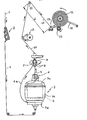
Un premier fil (1) est d'abord freiné par un frein progressif (2), puis il subit une fausse torsion. Un second fil (5) est freiné en (6) afin qu'on lui impose un effort très régulier. Les deux fils (1 et 5) passent dans un système tournant (7) comprenant deux poulies (9) solidaires qui assurent l'identité de l'avance de ces deux fils. Puis le fil composite ou câblé (10) traverse un système (1) arrêtant la progression de la torsion. Enfin le cablé (10) arrive à un dispositif de trancanage (13-15) en ayant soin de prévoir une grande distance (d) entre le dernier point (12) de guidage du fil au milieu de la course du guide-fil (13) et ce point (12) lui-même. Fabrication de câblés pour pneumatique.A first wire (1) is first braked by a progressive brake (2), then it undergoes a false twist. A second wire (5) is braked at (6) so that a very regular effort is imposed on it. The two wires (1 and 5) pass through a rotating system (7) comprising two pulleys (9) which are integral and which ensure the identity of the advance of these two wires. Then the composite or cabled wire (10) passes through a system (1) stopping the progression of the twist. Finally the cable (10) arrives at a cutting device (13-15) taking care to provide a large distance (d) between the last point (12) for guiding the wire in the middle of the course of the wire guide (13 ) and this point (12) itself. Manufacture of cables for tires.
Description
On sait que dans certaines applications, et plus particulièrement dans l'industrie des bandages pneumatiques, on exige des fils câblés qu'ils présentent des résistances à la traction très élevées. Or, cela n'exige pas seulement l'utilisation de matières textiles de haute qualité ; encore faut-il que les fibres constitutives de celles-ci et les fils élémentaires qui réalisent l'ensemble câblé soient sollicités très régulièrement par les efforts mis en jeu. Pour parvenir à satisfaire cette seconde condition, il est indispensable que les tensions et torsions mises en jeu au cours du câblage soient elles-mêmes strictement régulières sur toute la longueur du câblé considéré. Or, la pratique démontre que tel n'est pas le cas lorsqu'on utilise les dispositifs de câblage usuels et notamment ceux dits "de câblage direct". Il en résulte que si l'on considère par exemple une petite zone d'une enveloppe pneumatique comportant de tels fils câblés substantiellement parallèles les uns aux autres, les tensions ne se répartissent de façon régulière ni entre eux, ni entre leurs fibres ou autres éléments, de sorte que certains des fils sont déjà surchargés au moins localement quand d'autres ne subissent qu'une charge moyenne bien inférieure à ce qu'ils pourraient supporter. Cela limite la charge moyenne dans la zone considérée et oblige donc à utiliser des fils câblés plus gros, plus coûteux et plus lourds.It is known that in certain applications, and more particularly in the tire industry, cabled wires are required to have very high tensile strengths. This does not only require the use of high quality textile materials; still it is necessary that the constituent fibers thereof and the elementary son which realize the wired assembly are stressed very regularly by the forces involved. To achieve satisfying this second condition, it is essential that the tensions and twists put in play during the wiring are themselves strictly regular over the entire length of the cable in question. However, practice shows that this is not the case when using the usual wiring devices and in particular those called "direct wiring". As a result, if we consider for example a small area of a pneumatic envelope comprising such cabled wires substantially parallel to each other, the tensions are not evenly distributed between them, nor between their fibers or other elements. , so that some of the wires are already overloaded at least locally when others only undergo an average load much lower than they could bear. This limits the average load in the area considered and therefore requires the use of larger, more expensive and heavier cabled wires.
On a déjà proposé des têtes de câblage particulières grâce auxquelles la régularité du produit obtenu se trouve améliorée. Toutefois, les résultats qu'on a pu relever jusqu'ici ne sont nullement décisifs.Particular wiring heads have already been proposed thanks to which the regularity of the product obtained is improved. However, the results we have seen so far are by no means decisive.
L'invention vise à améliorer les dispositifs du genre en question.The invention aims to improve devices of the kind in question.
Conformément à l'invention, l'on procède de la façon suivante :
- 1° - On prélève à partir d'une réserve non tournante (bobine fixe, cantre) un premier fil substantiellement sans torsion importante et on le fait passer dans un dispositif de freinage progressif de manière à réaliser la parallélisation de ses brins constitutifs et la répartition régulière de la tension entre ceux-ci.
- 2° - On impartit à ce premier fil une fausse torsion en lui faisant traverser radialement le plateau de base d'une broche tournante portant la bobine de réserve d'un second fil.
- 3° - On fait comporter à la broche un dispositif de freinage de ce second fil, ledit dispositif étant prévu de façon à assurer une très grande régularité de l'effort qu'il impose au fil correspondant.
- 4°- On fait passer les deux fils dans un système tournant co-axial à la broche et comprenant deux poulies sur lesquelles ces fils s'enroulent au passage de façon à assurer l'identité de leurs avances, ce système étant entraîné par la réaction même des fils.
- 5° - On fait passer le fil composite ainsi obtenu par enroulement du premier et du second fil l'un sur l'autre à travers un système propre à arrêter la progression de la torsion, tel par exemple qu'un ensemble de poulies sur lesquelles ce fil s'enroule au passage.
- 6° - On amène enfin le fil composite précité, ou fil composite câblé, à un dispositif de bobinage à vitesse linéaire constante avec guide-fil mobile répartiteur des spires sur la longueur de la bobine, mais en ayant soin de prévoir, éventuellement à l'aide d'un renvoi, une grande distance entre le dernier point de guidage du fil et le guide-fil répartiteur qui assure le bobinage.
- 1 ° - We take from a non-rotating reserve (fixed spool, creel) a first wire substantially without significant twist and we pass it through a device progressive braking so as to achieve the parallelization of its constituent strands and the regular distribution of the tension between them.
- 2 ° - This first wire is imparted a false twist by making it radially cross the base plate of a rotating spindle carrying the reserve coil of a second wire.
- 3 ° - A braking device of this second wire is made to comprise the spindle, said device being provided so as to ensure a very great regularity of the force which it imposes on the corresponding wire.
- 4 ° - The two wires are passed through a rotating system coaxial with the spindle and comprising two pulleys on which these wires are wound in passing so as to ensure the identity of their advances, this system being driven by the reaction even sons.
- 5 ° - the composite yarn thus obtained is passed by winding the first and second yarn one over the other through a system capable of stopping the progression of torsion, such as for example a set of pulleys on which this wire is wound in the passage.
- 6 ° - Finally, the abovementioned composite wire, or cabled composite wire, is brought to a winding device at constant linear speed with a movable wire guide distributing the turns along the length of the coil, but taking care to plan, possibly at the 'using a return, a large distance between the last guide point of the wire and the distributor wire guide which ensures the winding.
Il est à noter que tous les éléments mis en oeuvre par l'invention sont en eux-mêmes connus, mais qu'ils n'avaient jamais été utilisés à la façon sus-exposée.It should be noted that all of the elements used by the invention are known in themselves, but that they had never been used in the manner described above.
Le dessin annexé, donné à titre d'exemple, permettra de mieux comprendre l'invention, les caractéristiques qu'elle présente et les avantages qu'elle est susceptible de procurer :
- La figure unique de ce dessin montre schématiquement une installation propre à la mise en oeuvre de l'invention.
- The single figure of this drawing schematically shows an installation specific to the implementation of the invention.
On a indiqué en 1 un premier fil provenant d'une réserve fixe telle qu'une bobine non tournante, un cantre, etc... Le fil 1 est substantiellement sans torsion ou du moins à torsion réduite, c'est-à-dire qu'il est fait de brins parallèles non serrés les uns contre les autres.We have indicated in 1 a first wire coming from a fixed reserve such as a non-rotating coil, a creel, etc. The
On lui fait traverser un premier dispositif de freinage 2 fait d'éléments successifs multiples, de façon à assurer la parallélisation des brins et la répartition régulière entre ceux-ci de la tension résultant du freinage. Le fil régularisé qui sort du dispositif 2 arrive à l'extrémité inférieure d'une broche creuse 3. Il pénètre dans celle-ci, mais en sort presque aussitôt à travers un canal percé radialement dans le plateau 3a de la broche. En raison de la rotation de celle-ci, il subit une fausse torsion et il forme un ballon tournant la qui entoure la cuvette 3b de la broche.It is made to pass through a
Cette cuvette 3b renferme une bobine 4 laquelle porte un second fil 5. Au sortir de la bobine 4, ce fil 5 traverse un second dispositif de freinage 6 porté par le couvercle 3c de la cuvette 3b et agencé de façon à assurer une force de freinage extrêmement régulière. On peut plus particulièrement util.iser à cet effet un frein de fil magnétique dans lequel ledit fil 5 est embarré plusieurs fois en vue de réaliser une régularité plus parfaite.This
Les deux fils 1 et 5 arrivent à un dispositif tournant 7 porté à rotation par un palier supérieur 8 monté dans l'axe de la broche 3. Ce dispositif comprend deux poulies 9 disposées suivant un même axe transversal à celui de la broche 3 et angulairement solidaires l'une de l'autre. Les fils s'enroulent au passage sur celles-ci, puis sortent ensemble à travers l'alésage de l'axe du dispositif 7. La présence des poulies 9 garantit que les avances ou débits des deux fils 1 et 5 sont toujours égaux.The two
Le fil composite 10 réalisé par l'ensemble des deux fils élémentaires 1 et 5 arrive ensuite à un dispositif 11 propre à empêcher la torsion de remonter plus loin. Ce dispositif 11 peut être constitué par un système à deux poulies ou davantage sur lesquelles le fil s'enroule au passage d'un angle important.The
Au sortir du dispositif 11, le fil 10 passe sur une poulie ou guide-fil de détour 12 qui le renvoie au guide-fil en va-et-vient 13 propre à assurer la formation régulière de la bobine 14 qui constitue le produit final désiré, cette bobine reposant sur un tambour d'entraînement 15 et étant maintenue par un ou deux bras tels que 16.Leaving the device 11, the
Bien entendu, la poulie ou guide-fil fixe 12 est disposée dans le plan passant par le point milieu de la course du guide-fil mobile 13, mais en outre la distance d qui sépare cette poulie 12 du point central précité est prévue aussi grande que le permettent les questions d'encombrement, de façon que les variations de la longueur de la partie du fil 10 comprise entre ladite poulie et le guide-fil mobile 13, et qui résultent du déplacement de ce dernier de part et d'autre du point central précité, soient aussi faibles que possible et n'aient pratiquement aucune influence sur la tension du fil enroulé sur la bobine.Of course, the pulley or fixed
On comprend que l'ensemble des dispositions sus-décrites permet d'obtenir finalement un câblé de constitution extrêmement régulière dans lequel toute tension éventuelle se répartit très régulièrement entre les divers brins et qui par conséquent présente une résistance à la traction pratiquement égale à la somme de celles de ceux-ci. ,,It will be understood that all of the above-described arrangements ultimately make it possible to obtain a cable of extremely regular constitution in which any possible tension is distributed very regularly between the various strands and which consequently has a tensile strength practically equal to the sum. of those. ,,
Claims (3)
Applications Claiming Priority (2)
| Application Number | Priority Date | Filing Date | Title |
|---|---|---|---|
| FR8408975A FR2565261B1 (en) | 1984-06-05 | 1984-06-05 | PROCESS FOR THE PRODUCTION OF HIGHLY REGULAR CABLES THREADS AND DEVICE FOR ITS IMPLEMENTATION |
| FR8408975 | 1984-06-05 |
Publications (2)
| Publication Number | Publication Date |
|---|---|
| EP0165188A2 true EP0165188A2 (en) | 1985-12-18 |
| EP0165188A3 EP0165188A3 (en) | 1986-08-13 |
Family
ID=9304821
Family Applications (1)
| Application Number | Title | Priority Date | Filing Date |
|---|---|---|---|
| EP85420105A Withdrawn EP0165188A3 (en) | 1984-06-05 | 1985-06-04 | Method and device for manufacturing regular ply yarns |
Country Status (4)
| Country | Link |
|---|---|
| US (1) | US4592195A (en) |
| EP (1) | EP0165188A3 (en) |
| JP (1) | JPS60259640A (en) |
| FR (1) | FR2565261B1 (en) |
Cited By (13)
| Publication number | Priority date | Publication date | Assignee | Title |
|---|---|---|---|---|
| EP0313877A1 (en) * | 1987-10-13 | 1989-05-03 | OFFICINE MECCANICHE RIVA S.r.l. | A twisting machine particularly for twisted threads |
| DE3743464A1 (en) * | 1987-12-22 | 1989-07-13 | Saurer Allma Gmbh | Apparatus for the production of twines, especially tyre cord |
| DE3817679C1 (en) * | 1988-05-25 | 1989-11-02 | Saurer-Allma Gmbh, 8960 Kempten, De | Cabling machine |
| FR2631978A1 (en) * | 1988-05-25 | 1989-12-01 | Saurer Allma Gmbh | IMPROVED ACTUATOR |
| FR2632981A1 (en) * | 1988-06-21 | 1989-12-22 | Icbt Lyon | WIRE WIRING MACHINE COMPRISING AN IMPROVED REGULATOR DEVICE |
| FR2632982A1 (en) * | 1988-06-21 | 1989-12-22 | Icbt Lyon | WIRE WIRING MACHINE |
| EP0480852A1 (en) * | 1990-10-11 | 1992-04-15 | Ic-Bt Lyon | Cabling machine for threads comprising regulating device |
| FR2667879A1 (en) * | 1990-10-11 | 1992-04-17 | Icbt Lyon | Machine for twisting (stranding) threads including an improved regulator device |
| FR2673956A1 (en) * | 1991-03-14 | 1992-09-18 | Ic Bt Lyon | Yarn cabling machine including an improved tension and length regulator assembly |
| WO1993011289A1 (en) * | 1991-11-26 | 1993-06-10 | E.I. Du Pont De Nemours And Company | A method for ply-twisting yarns without balloon limiters |
| EP0551787A1 (en) * | 1992-01-16 | 1993-07-21 | Emile Tardy S.A. | Machine for producing wrap yarns |
| FR2751667A1 (en) * | 1996-07-26 | 1998-01-30 | Saurer Allma Gmbh | Twisting head for a cable laying machine |
| US6775970B2 (en) | 2002-04-26 | 2004-08-17 | Leobardo Paulino Fernandez | Apparatus and method for making a hybrid cord |
Families Citing this family (7)
| Publication number | Priority date | Publication date | Assignee | Title |
|---|---|---|---|---|
| FR2583028B1 (en) * | 1985-06-11 | 1987-07-31 | Ic Acbf Sa | DEVICE FOR ADJUSTING THE TENSION OF A WIRE DURING DIFFERENT PROCESSING OPERATIONS WHICH IT UNDERGOES DURING ITS MANUFACTURE. |
| FR2586038B1 (en) * | 1985-08-07 | 1988-05-06 | Michelin & Cie | DEVICE AND METHOD FOR JOINING WIRES; WIRE ASSEMBLIES OBTAINED WITH THIS DEVICE AND METHOD |
| DE3708331C1 (en) * | 1987-03-14 | 1988-07-14 | Palitex Project Co Gmbh | Process for setting the thread tension ratio between the outer and inner thread in the production of cabled technical yarns and device for carrying out the process |
| FR2681612B1 (en) * | 1991-09-20 | 1993-11-05 | Icbt | IMPROVED MACHINE FOR CONTINUOUSLY CONDUCTING TWISTING AND ADDITIONAL TEXTURING TREATMENT ON A CHEMICAL WIRE. |
| ES2449218T3 (en) * | 2008-03-11 | 2014-03-18 | Invista Technologies S.À.R.L. | Wire formation procedures and apparatus for twisting or wiring wire |
| FR3004578B1 (en) | 2013-04-10 | 2015-05-01 | Verdol | DEVICE FOR MAINTAINING STATIONARY, IN AN ANGULAR POSITION REQUIRED, UNABLE TO STABILIZE ELEMENT AND USE OF THE DEVICE IN A TEXTILE YARN TRANSFORMATION MACHINE |
| CN104278368A (en) * | 2013-07-12 | 2015-01-14 | 张家港骏马涤纶制品有限公司 | Twisting device of direct twisting machine |
Citations (5)
| Publication number | Priority date | Publication date | Assignee | Title |
|---|---|---|---|---|
| FR1175229A (en) * | 1956-05-23 | 1959-03-23 | Deering Milliken Res Corp | Device for adjusting the advance and tension of the threads |
| GB831778A (en) * | 1957-04-23 | 1960-03-30 | Onderzoekings Inst Res | Improvements in apparatus for doubling two threads |
| FR1461336A (en) * | 1963-03-08 | 1966-02-25 | Cta | Device for pre-twisting continuous stranded threads |
| DE1510575A1 (en) * | 1966-03-25 | 1970-03-12 | Continental Gummi Werke Ag | Thread or cord composed of several pre-twists of different extensibility |
| US3724199A (en) * | 1970-04-20 | 1973-04-03 | Monsanto Co | Process for making continuous filament heather yarn |
Family Cites Families (4)
| Publication number | Priority date | Publication date | Assignee | Title |
|---|---|---|---|---|
| BE548196A (en) * | 1955-06-01 | |||
| US2961824A (en) * | 1955-06-20 | 1960-11-29 | Deering Milliken Res Corp | Apparatus for plying strands |
| US2949725A (en) * | 1957-06-06 | 1960-08-23 | Pirelli | Twisting head for two-fold yarn |
| US2902817A (en) * | 1957-10-09 | 1959-09-08 | American Enka Corp | Plying device |
-
1984
- 1984-06-05 FR FR8408975A patent/FR2565261B1/en not_active Expired
-
1985
- 1985-06-04 EP EP85420105A patent/EP0165188A3/en not_active Withdrawn
- 1985-06-04 US US06/741,087 patent/US4592195A/en not_active Expired - Fee Related
- 1985-06-05 JP JP60120736A patent/JPS60259640A/en active Pending
Patent Citations (5)
| Publication number | Priority date | Publication date | Assignee | Title |
|---|---|---|---|---|
| FR1175229A (en) * | 1956-05-23 | 1959-03-23 | Deering Milliken Res Corp | Device for adjusting the advance and tension of the threads |
| GB831778A (en) * | 1957-04-23 | 1960-03-30 | Onderzoekings Inst Res | Improvements in apparatus for doubling two threads |
| FR1461336A (en) * | 1963-03-08 | 1966-02-25 | Cta | Device for pre-twisting continuous stranded threads |
| DE1510575A1 (en) * | 1966-03-25 | 1970-03-12 | Continental Gummi Werke Ag | Thread or cord composed of several pre-twists of different extensibility |
| US3724199A (en) * | 1970-04-20 | 1973-04-03 | Monsanto Co | Process for making continuous filament heather yarn |
Cited By (18)
| Publication number | Priority date | Publication date | Assignee | Title |
|---|---|---|---|---|
| EP0313877A1 (en) * | 1987-10-13 | 1989-05-03 | OFFICINE MECCANICHE RIVA S.r.l. | A twisting machine particularly for twisted threads |
| DE3743464A1 (en) * | 1987-12-22 | 1989-07-13 | Saurer Allma Gmbh | Apparatus for the production of twines, especially tyre cord |
| US4932198A (en) * | 1988-05-25 | 1990-06-12 | Saurer-Allma Gmbh | Cabling machine |
| DE3817679C1 (en) * | 1988-05-25 | 1989-11-02 | Saurer-Allma Gmbh, 8960 Kempten, De | Cabling machine |
| FR2631978A1 (en) * | 1988-05-25 | 1989-12-01 | Saurer Allma Gmbh | IMPROVED ACTUATOR |
| FR2632981A1 (en) * | 1988-06-21 | 1989-12-22 | Icbt Lyon | WIRE WIRING MACHINE COMPRISING AN IMPROVED REGULATOR DEVICE |
| EP0348307A1 (en) * | 1988-06-21 | 1989-12-27 | Icbt Lyon | Machine for cabling threads comprising a regulation device |
| EP0348306A1 (en) * | 1988-06-21 | 1989-12-27 | Icbt Lyon | Machine for cabling threads |
| FR2632982A1 (en) * | 1988-06-21 | 1989-12-22 | Icbt Lyon | WIRE WIRING MACHINE |
| US4945720A (en) * | 1988-06-21 | 1990-08-07 | Icbt Lyon | Thread cabling machine having an improved regulator device |
| EP0480852A1 (en) * | 1990-10-11 | 1992-04-15 | Ic-Bt Lyon | Cabling machine for threads comprising regulating device |
| FR2667879A1 (en) * | 1990-10-11 | 1992-04-17 | Icbt Lyon | Machine for twisting (stranding) threads including an improved regulator device |
| FR2673956A1 (en) * | 1991-03-14 | 1992-09-18 | Ic Bt Lyon | Yarn cabling machine including an improved tension and length regulator assembly |
| WO1993011289A1 (en) * | 1991-11-26 | 1993-06-10 | E.I. Du Pont De Nemours And Company | A method for ply-twisting yarns without balloon limiters |
| EP0551787A1 (en) * | 1992-01-16 | 1993-07-21 | Emile Tardy S.A. | Machine for producing wrap yarns |
| FR2686354A1 (en) * | 1992-01-16 | 1993-07-23 | Tardy Sa Emile | MACHINE FOR THE PRODUCTION OF GUIPED WIRES. |
| FR2751667A1 (en) * | 1996-07-26 | 1998-01-30 | Saurer Allma Gmbh | Twisting head for a cable laying machine |
| US6775970B2 (en) | 2002-04-26 | 2004-08-17 | Leobardo Paulino Fernandez | Apparatus and method for making a hybrid cord |
Also Published As
| Publication number | Publication date |
|---|---|
| FR2565261B1 (en) | 1987-05-15 |
| US4592195A (en) | 1986-06-03 |
| EP0165188A3 (en) | 1986-08-13 |
| JPS60259640A (en) | 1985-12-21 |
| FR2565261A1 (en) | 1985-12-06 |
Similar Documents
| Publication | Publication Date | Title |
|---|---|---|
| EP0165188A2 (en) | Method and device for manufacturing regular ply yarns | |
| EP0217345B1 (en) | Method and apparatus for spinning staple fibre yarns | |
| FR2505372A1 (en) | STEEL CABLE FOR THE REINFORCEMENT OF AN ELASTOMERIC MATERIAL, PARTICULARLY FOR PNEUMATIC TIRES | |
| EP0022421B1 (en) | Method and apparatus for producing a yarn having along its length alternating opposite twist zones | |
| CH630543A5 (en) | METAL CABLE AND MANUFACTURING METHOD THEREOF. | |
| FR2560230A1 (en) | PROCESS FOR OBTAINING A FIBER FILE | |
| FR2483967A1 (en) | PREFERRED WIRE RING | |
| FR2558488A1 (en) | METHOD FOR FILING CUTTING FIBERS | |
| EP0279756A1 (en) | Multifilament sewing thread and method for making the same | |
| EP0211387B2 (en) | Apparatus and method for assembling yarns, assembling yarns obtained by means of this apparatus and this method | |
| WO2009027615A2 (en) | Hybrid thread and method for making same | |
| FR2521599A1 (en) | METHOD AND APPARATUS FOR MANUFACTURING YARNS HAVING VARIOUS STRUCTURES | |
| EP0070210B1 (en) | Method and apparatus of manufacturing a doubled yarn | |
| US4237683A (en) | Device for delivering yarns | |
| FR2548692A1 (en) | TEXTILE PRODUCT TYPE FIBER FIBER, METHOD AND DEVICE FOR MANUFACTURING THE SAME | |
| FR2476692A1 (en) | DEVICE FOR THE PRODUCTION OF EFFECT YARN | |
| FR2920787A1 (en) | Hybrid thread for manufacturing e.g. technical fabric, has two groups of elementary threads assembled by direct cabling method, where one group comprises high-tenacity threads arranged in pot of direct cabling pin | |
| SU239090A1 (en) | METHOD OF FORMING WRONG THREADS | |
| FR2629843A1 (en) | METHOD AND DEVICE FOR MANUFACTURING STEEL WIRE TORONES WITH VARIABLE TORONING STRUCTURE | |
| FR2597120A1 (en) | METHOD FOR PRODUCING AN ARMED WIRE, DEVICE FOR IMPLEMENTING IT, AND ARMED WIRE OBTAINED BY SAID METHOD | |
| RU2085631C1 (en) | Chemical thread production method | |
| FR2492853A3 (en) | Flax wet-spinning machine - has condenser system with sleeve enclosing acute angle as it passes around rounded sleeve-guide | |
| BE1002753A3 (en) | Process and device for feeding at least two ring-spinning frame stationsusing a drawn rove | |
| BE497655A (en) | ||
| FR2528456A2 (en) | Doubled core-spun yarn - produced by false-twisting two yarns together followed by separate high-speed up-twisting |
Legal Events
| Date | Code | Title | Description |
|---|---|---|---|
| PUAI | Public reference made under article 153(3) epc to a published international application that has entered the european phase |
Free format text: ORIGINAL CODE: 0009012 |
|
| AK | Designated contracting states |
Designated state(s): BE CH DE FR GB IT LI NL |
|
| PUAL | Search report despatched |
Free format text: ORIGINAL CODE: 0009013 |
|
| AK | Designated contracting states |
Kind code of ref document: A3 Designated state(s): BE CH DE FR GB IT LI NL |
|
| 17P | Request for examination filed |
Effective date: 19860923 |
|
| 17Q | First examination report despatched |
Effective date: 19880125 |
|
| STAA | Information on the status of an ep patent application or granted ep patent |
Free format text: STATUS: THE APPLICATION IS DEEMED TO BE WITHDRAWN |
|
| 18D | Application deemed to be withdrawn |
Effective date: 19880826 |
|
| RIN1 | Information on inventor provided before grant (corrected) |
Inventor name: CHARBONNIER, SIMON |