EP0165175A2 - Outlet and ventilating installation controllable in response to the temperature and the humidity fraction of the air stream - Google Patents
Outlet and ventilating installation controllable in response to the temperature and the humidity fraction of the air stream Download PDFInfo
- Publication number
- EP0165175A2 EP0165175A2 EP85401129A EP85401129A EP0165175A2 EP 0165175 A2 EP0165175 A2 EP 0165175A2 EP 85401129 A EP85401129 A EP 85401129A EP 85401129 A EP85401129 A EP 85401129A EP 0165175 A2 EP0165175 A2 EP 0165175A2
- Authority
- EP
- European Patent Office
- Prior art keywords
- mouth
- bimetallic strip
- air
- extraction
- intake
- Prior art date
- Legal status (The legal status is an assumption and is not a legal conclusion. Google has not performed a legal analysis and makes no representation as to the accuracy of the status listed.)
- Withdrawn
Links
Images


Classifications
-
- G—PHYSICS
- G05—CONTROLLING; REGULATING
- G05D—SYSTEMS FOR CONTROLLING OR REGULATING NON-ELECTRIC VARIABLES
- G05D23/00—Control of temperature
- G05D23/19—Control of temperature characterised by the use of electric means
- G05D23/275—Control of temperature characterised by the use of electric means with sensing element expanding, contracting, or fusing in response to changes of temperature
-
- F—MECHANICAL ENGINEERING; LIGHTING; HEATING; WEAPONS; BLASTING
- F24—HEATING; RANGES; VENTILATING
- F24F—AIR-CONDITIONING; AIR-HUMIDIFICATION; VENTILATION; USE OF AIR CURRENTS FOR SCREENING
- F24F11/00—Control or safety arrangements
- F24F11/0001—Control or safety arrangements for ventilation
-
- F—MECHANICAL ENGINEERING; LIGHTING; HEATING; WEAPONS; BLASTING
- F24—HEATING; RANGES; VENTILATING
- F24F—AIR-CONDITIONING; AIR-HUMIDIFICATION; VENTILATION; USE OF AIR CURRENTS FOR SCREENING
- F24F11/00—Control or safety arrangements
- F24F11/70—Control systems characterised by their outputs; Constructional details thereof
- F24F11/72—Control systems characterised by their outputs; Constructional details thereof for controlling the supply of treated air, e.g. its pressure
- F24F11/74—Control systems characterised by their outputs; Constructional details thereof for controlling the supply of treated air, e.g. its pressure for controlling air flow rate or air velocity
-
- F—MECHANICAL ENGINEERING; LIGHTING; HEATING; WEAPONS; BLASTING
- F24—HEATING; RANGES; VENTILATING
- F24F—AIR-CONDITIONING; AIR-HUMIDIFICATION; VENTILATION; USE OF AIR CURRENTS FOR SCREENING
- F24F13/00—Details common to, or for air-conditioning, air-humidification, ventilation or use of air currents for screening
- F24F13/08—Air-flow control members, e.g. louvres, grilles, flaps or guide plates
- F24F13/10—Air-flow control members, e.g. louvres, grilles, flaps or guide plates movable, e.g. dampers
-
- G—PHYSICS
- G05—CONTROLLING; REGULATING
- G05D—SYSTEMS FOR CONTROLLING OR REGULATING NON-ELECTRIC VARIABLES
- G05D23/00—Control of temperature
- G05D23/19—Control of temperature characterised by the use of electric means
- G05D23/1902—Control of temperature characterised by the use of electric means characterised by the use of a variable reference value
Definitions
- the present invention relates to a device for controlling the flow of air extracted from a room or admitted into it as a function of the temperature and the hygrometric degree of this air.
- the parameter taken into account is la. temperature of the extracted gas.
- the only application of these devices is carried out for gas extraction conduits ensuring simultaneously the ventilation of the room and the evacuation of the burnt gases from a gas generator.
- the operation of the generator generates the production of hot gases in the direction of the ventilation opening which reacts by moving the shutter in its position of maximum opening to let a large flow of gas pass through it.
- the temperature of the gases passing through the mouth decreases and the shutter resumes a position of weakest opening of the mouth limiting the flow rate to the only needs of the ventilation of the room.
- the aim of the present invention is to overcome the drawbacks of these existing devices by proposing a ventilation opening both for the extraction and the admission of air sensitive to the absolute humidity level of the air or of the gases extracted or admitted, while being capable of being mounted in a particular embodiment on a conduit for extracting combustion gases from a boiler.
- the subject of the invention is an air or gas extraction or admission mouth for the ventilation of a room, comprising an adjustable shutter constituted by a bimetallic strip sensitive to temperature and coupled to said mouth to constitute a movable member for adjusting the gas passage section inside the mouth and whose position in said section is such that it has a face subjected to the flow F of air tending to become more and more convex during a rise in temperature, characterized in that said bimetallic strip is equipped with a means for supplying calories additional controlled by an air humidity detector.
- a humidity detector as a main example, but the scope of the invention must be extended to any detector of polluting gas and in particular carbon dioxide, the presence of which is significant. occupancy of the premises and implies the need for ventilation.
- the means for providing additional calories consists of an electrical resistance fixed to said bimetallic strip connected to a current source by means of a supply circuit in which the rate detector humidity is a device for controlling its closing and opening.
- said resistor is integrated in a thin sheet glued to said bimetallic strip.
- Said detector can also be designed as a sensitive plate which can be dismantled with respect to a support for fixing and electrical connection to said bimetal supply circuit.
- the electrical circuit for supplying the resistor will include a manual switch arranged on the circuit to connect to said circuit a member for controlling the opening of this circuit, independent of the humidity detector.
- Another particularly interesting object of the invention lies in a ventilation installation comprising at least one extraction mouth and at least one intake mouth according to the invention, characterized in that it comprises a sensor of the current passing through the heating resistor of each bimetallic strip, connected to a control member for the opening and closing of the supply circuit of the heating resistor of the other bimetallic strip, acting on said circuit independently of the state of the humidity associated with it.
- This enslavement has the disadvantage that the fresh air necessary to overcome the humidity created in the kitchen, or in another technical room such as the bathroom, passes through the entire housing and helps to cool it.
- the inventor has been able to observe that the servo-control is not essential between the opening of an air intake mouth and the extraction vents. Indeed, the increase in flow rates which results from the opening of a single air inlet is reduced, and the balance of flow rates is obtained by a slight decrease in inlet flow rate in the unoccupied rooms.
- the present invention further aims to solve the new additional technical problem consisting of a simplification, and therefore better rationalization, of the design and operation of the vents and ventilation installations, in particular by eliminating the aforementioned servo provided between the opening of the intake and fresh air vents and those for extracting stale air without reducing the efficiency of its ventilation.
- the present invention also relates to a ventilation installation comprising at least one intake and / or extraction mouth as defined above, characterized in that said intake mouth when it is located in a room technical, such as kitchen, bathroom, does not include a humidity detector while the adjustable shutter, preferably a bimetallic strip, is controlled in parallel with that of the extraction mouth.
- the intake openings of the noble pieces are autonomous and of the humidity sensitive type and are not controlled by the opening of an extraction mouth.
- the opening of the air inlet of the intake mouth is delayed (or has a lower flow rate), compared to that of the extraction mouth so as to maintain a vacuum in said room, and therefore in said housing, so as to avoid a short-circuiting of the minimum ventilation of the noble or main rooms.
- the extraction mouth is made more simply. It includes a humidity detector and preferably also a manual control.
- the inlet mouth is not started until a certain extraction threshold for the extraction mouth.
- the flow rate of the inlet mouth can be zero when the flow rate of the extraction mouth is less than or equal to 40 m 3 / h and the flow rate of the mouth can be 95 cm 3 / h when the flow rate from the extraction outlet is 135 m per hour.
- FIG. 1 we see a ventilation channel 1, through the walls 2 of which an air intake 3 is provided to communicate this channel 1 with the air contained in a room 4, by -example a kitchen.
- This air intake 3 is equipped with a ventilation mouth 5, which will be described in more detail below, to which a duct 6 can be connected.
- This duct symbolizes the means for collecting the combustion gases from a heating boiler which is not shown and / or the polluted gases released by the kitchen appliances, passing through a hood which is also not shown. This duct is not necessary if there is no hood or gas generator.
- the mouth 5 is essentially constituted by a tube section 7 of rectangular, square or other suitable shape provided with a fixing flange 8, inside which is arranged a bimetallic strip 9 curved so as to present its convex face to the flow F of gas.
- This bimetallic strip constitutes a variable shutter of the passage section of the tube 7 between a maximum obturation position such as that shown and defined by an adjustable stop not shown (for example a screw penetrating at its upper part into the section of the tube) and a position of maximum opening in which the bimetallic strip 8 bears on the stop 10.
- an adjustable stop not shown for example a screw penetrating at its upper part into the section of the tube
- the concave face of the bimetallic strip 9 is further equipped with a resistor 11 shown here in the form of an adhesive film or bimetallic strip.
- a resistor 11 shown here in the form of an adhesive film or bimetallic strip.
- This heating element by Joule effect is connected to a source of electrical current supply (here the secondary of a transformer 12) by means of an electronic circuit 13 which essentially fulfills a role of current modulator controlled by a detector of humidity 14.
- This circuit will preferably consist of a triac, the trigger of which is controlled by the humidity detector.
- the detector 14 can simply be constituted by a body whose electrical resistance varies as a function of the humidity level. Powered by the secondary of the transformer 12, it can, beyond a certain conductivity threshold, deliver the voltage necessary for unlocking the aforementioned triac integrated in the circuit 13.
- the detector 14 is removable with respect to a fixed support which may include the circuit 13.
- This arrangement is advantageous because it allows, by simply removing the sensitive plate which forms the detector, a replacement easy of the latter, which can in use. be covered with an impermeable fatty layer.
- the plate and its support can be placed in a place in the room remote from the source of emission of the stale gases, in particular to reduce the fouling thereof, and possibly allow this detector to be placed in a place of the room far from the source of emission of the stale gases to, in particular, reduce the clogging and, possibly allow to place this detector in a place at a lower temperature than at the level of the mouth, therefore or the relative humidity is higher. It may however be advantageous to place this detector in the duct for extracting the products of combustion of a condensing boiler in order to modulate the flow rate extracted after the shutdown or operation of the boiler, a very attractive solution for dwellings or apartments. one or two main rooms.
- the resistor 11 supply circuit includes a manual switch 15 which can, for example, connect the trigger of the triac to an adequate voltage source forming a secondary control member thus allowing the supply of the resistor 11 to be controlled independently of the humidity level existing and detected and possibly controlled by a central heating programming unit.
- the bimetallic strip 9 is sensitive to the temperature of the gas flow F.
- this gas consists of the combustion products of a boiler, their high temperature will place the bimetallic strip in its opening configuration allowing the evacuation of gas flow rates necessary for the proper functioning of the boiler. After the boiler operating sequence, the opening will be reduced by the cooling bimetallic strip 9, thus limiting the ventilation rate to normal needs.
- the gases collected are at a temperature lower than those of combustion and the position of the bimetallic strip varies only slightly from that of minimum flow which is often insufficient to ventilate the room properly. It is at this moment that the humidity plate 14 intervenes because in these periods the humidity rate increases.
- the resistor 11 is then supplied and heats the bimetallic strip 9 which opens the mouth further.
- Another advantage of the invention resides in the possibility of using the same control voltage of the triac of circuit 13 to modulate, in a single-family house, the speed of the exhaust fan by means of another triac and of thus adjust this speed to the strict needs corresponding to the degree of opening of the mouth.
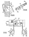
- FIG. 2A shows an air intake opening 20 made, for example, in the window frame 21 of a window and provided with an air intake mouth essentially comprising an external deflector 22, a calibrated orifice and profile 23 formed in an inner plate 24 and an inner deflector 25.
- bimetallic strip is thin enough to be elastically deformable towards the orifice 23 under the effect of a pressure difference existing between the outside and the inside of the window, due for example to the presence of wind.
- This bimetallic strip plays, in a known manner, the role of movable shutter flap giving the mouth a self-adjusting character, that is to say of stabilizing the air inlet flow whatever the pressure difference between the interior and the outside.
- the bimetallic strip 27 is equipped with a film 28 electrically resistant on one of its faces, connected (wires 29) to a supply circuit comprising, as in FIG. 1, a triac and a humidity detector.
- the position 27a of the bimetallic strip shown in solid lines in FIG. 2A symbolizes the rest position corresponding to ambient conditions in which there is no wind, a relatively low internal humidity rate leading to an admission flow d 'average air.
- the position 27b of the bimetallic strip shown in phantom is the result of the existence of wind on the facade of the building or of cold air. This intake flow is then reduced to a minimum, the ambient humidity level remaining low.
- the position 27c of the bimetallic strip is that which it takes in the presence of an excessively high internal humidity rate which has generated a heating spreading the bimetallic strip from the orifice 23 and allowing the admission of an air flow more important. It will be recalled that FIG.
- FIG. 2A is a diagrammatic cross-section of the inlet mouth according to the invention and that the positions indicated are those taken by the central part of the bimetal strip which is held in a sliding manner by its two ends in the slides 26a and 26b. It will be noted that, also with regard to the air intake vents, it may be advantageous to provide a forced opening control to favor the renewal of air through a living room which would be polluted by the smoke. of cigarettes.
- the device according to the invention it is possible by the device according to the invention to control the extraction and the admission of air to the temperature, to the humidity rate and also to take into account the external atmospheric conditions. the room to be ventilated.
- a control of the air flow entering an apartment implies a correlative control of the extracted air flow, and vice versa, so that ventilation is optimized.
- the inlet mouth is denoted 30 and includes the humidity detector 31, the additional resistance 32 of the bimetallic strip (heating film) in series across the secondary of the transformer 12 with one. triac 33 on the trigger 33a which acts the humidity detector 31.
- the extraction mouth is denoted 40 and includes the humidity detector 41, the additional resistance 42 of the bimetallic strip (heating film) in series across the transformer secondary 12 with a triac 43 on the trigger 43a which acts the humidity detector 41.
- Also in series on the triac detector circuit of each mouth is the primary of a step-up transformer 34, 44 whose voltage delivered by the secondary is applied for the transformer 34, to the trigger 43a and for the transformer 44, to the trigger 33a.
- the connection between the secondary of the transformer 34 and the trigger 43a can be interrupted by a manual switch (inverter) which can connect the trigger in its other position to an adequate voltage source. (from a divider 45).
- a manual switch inverter
- the control of each mouth 30, 40 is controlled by the operation of the other.
- the control of the extraction mouth 40 is forced and the control of the intake mouth 30 is controlled by the operation of the extraction mouth 40.
- a switch which would force the opening of the air intake mouth 30, but it is not departing from the scope of the present invention to provide it for, for example, favor the ventilation of a living room where you smoke. In this case, the opening of the extraction mouth 40 will be slaved to that of the mouth kept forced open.
- the heating of the bimetallic strip of a mouth 30 or 40 controlled by the plate 31 or 41 sensitive to the corresponding humidity is the result of the circulation of a charging current through the triac 33 or 43 turned on, this current generating by the transformer 34 or 44 a trigger control voltage 43a or 33a of the other triac 43, 33 making it passing in a ratio corresponding to the intensity of the load current.
- the bimetallic strip of the other mouth is therefore heated to an extent related to the bimetallic strip of the first mouth and the openings of the mouths are then in a relationship allowing good ventilation.
- FIG. 3 relates to the assertion of an extraction mouth to a single intake mouth.
- Each of the intake ports of a dwelling can be connected to the mouth of the kitchen of the same way on condition that a transformer 44 is used having as many secondaries as there are air inlets.
- transformers 34, 44 are only one possible example of sensors for the passage of current in the charging circuit of triacs capable of controlling the trigger.
- Other components can be used such as for example thermistors from other triacs or others making it possible to deliver a current or a voltage controlled as a function of a detected current.
- This inlet mouth 18 is preferably constructed on the same principle as that described in the main patent and shown in FIGS. 2A and 2B and reference will be made to these figures to understand the structure of this mouth.
- this inlet mouth 18 is of the thermoregulating type and also comprises the bimetallic strip 27 shown in attached FIG. 2A constituting the adjustable shutter, which is equipped with a film 28 electrically resistant on one of its faces, and which is connected by wires 29 to the supply circuit 13, being controlled in parallel with that of the mouth 5.
- the installation. ventilation is provided so that the noble rooms or main rooms are equipped with humidity-sensitive intake vents which can be of any humidity-sensitive model and in particular that previously described.
- These intake openings for soft rooms are autonomous and are no longer required to be controlled by the opening of an extraction opening, contrary to what is described in FIGS. 1 to 3.
- the opening of the inlet mouth 18 of the technical part is delayed relative to that of the extraction mouth 5 so as to maintain a vacuum in said part.
- the humidity plate 14 sends a signal to the circuit 13 which then heats the bimetallic strips of the extraction mouth 5 and of the intake mouth 18 in parallel.
- the supply of the bimetallic strip to the inlet mouth 18 can be delayed so as to maintain a vacuum in the housing.
- the invention also makes it possible, as previously described, to simplify the structure of the ventilation installation, by eliminating the need for servo-control between the intake mouth and the extraction mouth. This also eliminates the risk of breakdown due to a failure of the servo system.
- the invention offers the additional technical advantage of making it possible to connect a gas generator which requires a large flow of air.
- the invention finds an interesting explanation in the ventilation and air conditioning industry.
Landscapes
- Engineering & Computer Science (AREA)
- Physics & Mathematics (AREA)
- Chemical & Material Sciences (AREA)
- Combustion & Propulsion (AREA)
- Mechanical Engineering (AREA)
- General Engineering & Computer Science (AREA)
- Fluid Mechanics (AREA)
- General Physics & Mathematics (AREA)
- Automation & Control Theory (AREA)
- Ventilation (AREA)
Abstract
Description
La présente invention concerne un dispositif de contrôle du débit d'air extrait d'un local ou admis dans celui-ci en fonction de la température et du degré hygrométrique de cet air.The present invention relates to a device for controlling the flow of air extracted from a room or admitted into it as a function of the temperature and the hygrometric degree of this air.
Il est connu de contrôler la ventilation forcée d'un local, par exemple, d'habitation, en fonction des conditions d'utilisation de ce local qui sont variables au cours de l'année et de la journée. Pour ce faire, on dispose dans chaque (ou certains) orifices d'entrée ou de sortie d'air un obturateur dont la position détermine le débit d'air admis ou extrait. Le réglage de cette position est, pour chaque bouche,assuré soit manuellement par l'usager, soit automatiquement au moyen d'un dispositif d'asservissement qui est sensible à un-paramètre significatif de ces conditions d'utilisation.It is known to control the forced ventilation of a room, for example, a dwelling, according to the conditions of use of this room which are variable during the year and the day. To do this, there is in each (or certain) air inlet or outlet orifices a shutter whose position determines the flow of air admitted or extracted. The adjustment of this position is, for each mouth, carried out either manually by the user, or automatically by means of a servo device which is sensitive to a significant parameter of these conditions of use.
C 'est ainsi que dans certaines bouches connues il est prévu de prendre en compte le degré hygrométrique de l'air de la pièce à ventiler, qui est significatif de l'occupation de cette pièce. Cette disposition trouve une application intéressante pour des pièces de séjour, et des chambres en ce qui concerne l'entrée d'air et des cuisines, salles de bain et W.C. pour ce qui concerne l'extraction.It is thus that in certain known outlets it is planned to take into account the humidity of the air in the room to be ventilated, which is significant for the occupation of this room. This arrangement finds an interesting application for living rooms, and bedrooms with regard to air intake and kitchens, bathrooms and W.C. with regard to extraction.
Dans d'autres systèmes, le paramètre pris en considération est la. température du gaz extrait. La seule application de ces dispositifs est réalisée pour des conduits d'extraction de gaz assurant simultanément la ventilation du local et l'évacuation des gaz brûlés d'un générateur à gaz. Ainsi le fonctionnement du générateur engendre la production de gaz chauds en direction de la bouche de ventilation qui réagit en déplaçant l'obturateur dans sa position d'ouverture maximale pour laisser un grand débit de gaz la traverser. Lorsque le générateur cesse de fonctionner, la température des gaz traversant la bouche diminue et l'obturateur reprend une position de plus faible ouverture de la bouche limitant le débit de passage aux seuls besoins de la ventilation du local.In other systems, the parameter taken into account is la. temperature of the extracted gas. The only application of these devices is carried out for gas extraction conduits ensuring simultaneously the ventilation of the room and the evacuation of the burnt gases from a gas generator. Thus the operation of the generator generates the production of hot gases in the direction of the ventilation opening which reacts by moving the shutter in its position of maximum opening to let a large flow of gas pass through it. When the generator stops working, the temperature of the gases passing through the mouth decreases and the shutter resumes a position of weakest opening of the mouth limiting the flow rate to the only needs of the ventilation of the room.
Il existe également des dispositifs dans lesquels on prend en compte, par deux organes indépendants, le degré hygrométrique et la température pour commander l'ouverture de la bouche. Ce sont des bouches d'extraction pour ventiler une cuisine et évacuer les gaz d'un générateur. Leur installation dans une cuisine n'est pas satisfaisante car c'est le taux d'humidité relative qui est pris en compte. Or dans une cuisine la température croît en même temps que l'humidité si bien que l'humidité relative croît beaucoup plus lentement que l'élévation d'humidité absolue et le degré d'ouverture de la bouche s'avère insuffisant pour la ventilation correcte du local lorsque le générateur ne fonctionne pas, c'est-à-dire lorsque l'organe sensible à la température n'est pas mis en action. Il est alors nécessaire de maintenir la bouche de ventilation ouverte au moyen d'une commande manuelle qui la plupart du temps est négligée par l'utilisateur peu sensibilisé par ce problème.There are also devices in which the hygrometric degree and the temperature are taken into account by two independent members to control the opening of the mouth. These are extraction vents to ventilate a kitchen and evacuate gases from a generator. Their installation in a kitchen is not satisfactory because it is the relative humidity rate that is taken into account. However in a kitchen the temperature increases at the same time as the humidity so that the relative humidity increases much more slowly than the increase in absolute humidity and the degree of opening of the mouth proves to be insufficient for the correct ventilation from the room when the generator does not work, that is to say when the temperature-sensitive member is not put into action. It is then necessary to keep the ventilation opening open by means of a manual control which most of the time is neglected by the user little aware of this problem.
D'une manière générale dans les systèmes asservis à la température, il est également utile de prévoir une commande manuelle d'ouverture de la bouche pour q'une ventilation correcte du local puisse avoir lieu quand simplement les gaz et vapeurs de cuisine sont produits. En effet, ces gaz ne sont pas à une température suffisante pour déclencher par eux-mêmes l'ouverture du registre obturateur. En outre, l'ouverture ou la fermeture des bouches d'entrées d'air est restée jusqu'à ce jour indépendante de celle des bouches d'extraction, ce qui ne peut satisfaire de manière rationnelle la condition d'égalité de la somme des débits d'air entrant et de celle des débits d'air sortant. Les bouches existantes conduisent donc à des prises ou des évacuations d'air parasites incontrôlées.Generally in temperature-controlled systems, it is also useful to provide an order manual opening of the mouth so that correct ventilation of the room can take place when the kitchen gases and vapors are simply produced. In fact, these gases are not at a sufficient temperature to trigger the opening of the shutter register by themselves. In addition, the opening or closing of the air intake vents has so far remained independent of that of the extraction vents, which cannot rationally satisfy the condition of equality of the sum of the incoming air flows and that of the outgoing air flows. Existing outlets therefore lead to uncontrolled parasitic air intakes or evacuations.
La présente invention a pour but de pallier les inconvénients de ces dispositifs existants en proposant une bouche de ventilation tant pour l'extraction que l'admission d'air sensible au taux d'humidité absolu de l'air ou des gaz extraits ou admis, tout en étant capable d'être montée dans une variante de réalisation particulière sur un conduit d'extraction des gaz de combustion d'une chaudière.The aim of the present invention is to overcome the drawbacks of these existing devices by proposing a ventilation opening both for the extraction and the admission of air sensitive to the absolute humidity level of the air or of the gases extracted or admitted, while being capable of being mounted in a particular embodiment on a conduit for extracting combustion gases from a boiler.
A cet effet, l'invention a pour objet une bouche d'extraction ou d'admission d'air ou de gaz pour la ventilation d'un local, comportant un obturateur réglable constitué par un bilame sensible à la température et attelé à ladite bouche pour constituer un organe mobile de réglage de la section de passage des gaz à l'intérieur de la bouche et dont la position dans ladite section est telle qu'il comporte une face soumise au flux F d'air tendant à devenir de plus en plus convexe lors d'une élévation de température,caractérisée en ce que ledit bilame est équipé d'un moyen d'apport de calories additionnel commandé par un détecteur de taux d'humidité de l'air. Il convient de noter que le texte et les revendications mentionnent un détecteur d'humidité à titre d'exemple principal mais il faut étendre la portée de l'invention à tout détecteur de gaz polluant et notamment de gaz carbonique dont la présence est significative d'une occupation des locaux et implique la nécessité d'une ventilation.To this end, the subject of the invention is an air or gas extraction or admission mouth for the ventilation of a room, comprising an adjustable shutter constituted by a bimetallic strip sensitive to temperature and coupled to said mouth to constitute a movable member for adjusting the gas passage section inside the mouth and whose position in said section is such that it has a face subjected to the flow F of air tending to become more and more convex during a rise in temperature, characterized in that said bimetallic strip is equipped with a means for supplying calories additional controlled by an air humidity detector. It should be noted that the text and the claims mention a humidity detector as a main example, but the scope of the invention must be extended to any detector of polluting gas and in particular carbon dioxide, the presence of which is significant. occupancy of the premises and implies the need for ventilation.
Dans un mode de réalisation de l'invention, le moyen d'apport additionnel de calories est constitué par une résistance électrique fixée audit bilame connectée à une source de courant au moyen d'un circuit d'alimentation dans lequel le détecteur du taux d'humidité est un organe de commande de sa fermeture et de son ouverture.In one embodiment of the invention, the means for providing additional calories consists of an electrical resistance fixed to said bimetallic strip connected to a current source by means of a supply circuit in which the rate detector humidity is a device for controlling its closing and opening.
Dans un mode préféré de réalisation, ladite résistance est intégrée dans une feuille mince collée audit bilame.In a preferred embodiment, said resistor is integrated in a thin sheet glued to said bimetallic strip.
Il sera par ailleurs avantageux de prévoir l'installation du détecteur d'humidité séparément et à distance de celle de la bouche elle-même pour notamment réduire l'encrassage de celui-ci par les particules grasses ou non gazeuses véhiculées par l'air à extraire.It will also be advantageous to provide for the installation of the humidity detector separately and at a distance from that of the mouth itself, in particular to reduce the fouling thereof by fatty or non-gaseous particles conveyed by the air at extract.
On pourra également concevoir ledit détecteur comme une platine sensible démontable par rapport à un support de fixation et de connexion électrique audit circuit d'alimentation du bilame.Said detector can also be designed as a sensitive plate which can be dismantled with respect to a support for fixing and electrical connection to said bimetal supply circuit.
Enfin, dans une variante avantageuse le circuit électrique d'alimentation de la résistance comportera un commutateur manuel disposé sur le circuit pour connecter audit circuit un organe de commande de l'ouverture de ce circuit, indépendant du détecteur d'humidité.Finally, in an advantageous variant, the electrical circuit for supplying the resistor will include a manual switch arranged on the circuit to connect to said circuit a member for controlling the opening of this circuit, independent of the humidity detector.
Un autre objet particulièrement intéressant de l'invention réside dans une installation de ventillation comportant au moins une bouche d'extraction et au moins une bouche d'admission conformes à l'invention, caractérisée en ce qu'elle comporte un capteur du courant traversant la résistance de chauffage de chaque bilame, connecté à un organe de commande de l'ouverture et de la fermeture du circuit d'alimentation de la résistance de chauffage de l'autre bilame, agissant sur ledit circuit indépendamment de l'état du détecteur d'humidité qui lui est associé.Another particularly interesting object of the invention lies in a ventilation installation comprising at least one extraction mouth and at least one intake mouth according to the invention, characterized in that it comprises a sensor of the current passing through the heating resistor of each bimetallic strip, connected to a control member for the opening and closing of the supply circuit of the heating resistor of the other bimetallic strip, acting on said circuit independently of the state of the humidity associated with it.
Cet asservissement présente l'inconvénient que l'air neuf nécessaire à vaincre l'humidité créée dans la cuisine, ou dans une autre pièce technique telle que la salle de bains, transite par tout le logement et contribue à le refroidir.This enslavement has the disadvantage that the fresh air necessary to overcome the humidity created in the kitchen, or in another technical room such as the bathroom, passes through the entire housing and helps to cool it.
D'autre part, l'inventeur a pu constater que l'asservissement ne s'avère pas indispensable entre l'ouverture d'une bouche d'entrée d'air et les bouches d'extraction. En effet, l'augmentation des débits qui résulte de l'ouverture d'une seule entrée d'air est réduite, et l'équilibre des débits s'obtient par une légère diminution de débit d'entrée dans les pièces inoccupées.On the other hand, the inventor has been able to observe that the servo-control is not essential between the opening of an air intake mouth and the extraction vents. Indeed, the increase in flow rates which results from the opening of a single air inlet is reduced, and the balance of flow rates is obtained by a slight decrease in inlet flow rate in the unoccupied rooms.
Par contre, si plusieurs entrées sont sollicitées par l'augmentation de l'humidité intérieure, le détecteur de la bouche placée en cuisine sera donc sollicité et provoquera l'ouverture nécessaire de cette bouche.On the other hand, if several inputs are requested by the increase in interior humidity, the detector of the mouth placed in the kitchen will therefore be requested and will cause the necessary opening of this mouth.
La présente invention a en outre pour but de résoudre le nouveau problème technique supplémentaire consistant en une simplification, et donc meilleure rationalisation, de la conception et du fonctionnement des bouches et installations de.ventilation, notamment en éliminant l'asservissement précité prévu entre l'ouverture des bouches d'entrée et d'air neuf et celles d'extraction d'air vicié sans pour autant diminuer l'efficacité de sa ventilation.The present invention further aims to solve the new additional technical problem consisting of a simplification, and therefore better rationalization, of the design and operation of the vents and ventilation installations, in particular by eliminating the aforementioned servo provided between the opening of the intake and fresh air vents and those for extracting stale air without reducing the efficiency of its ventilation.
Ce nouveau problème technique est aussi résolu pour la première fois par la présente invention.This new technical problem is also solved for the first time by the present invention.
Ainsi, la présente invention concerne encore une installation de ventilation comportant au moins une bouche d'admission et/ou d'extraction telle -que ci-dessus définie, caractérisée en ce que ladite bouche d'admission lorsqu'elle est située dans une pièce technique, telle que cuisine, salle de bains, ne comporte pas de détecteur d'humidité tandis que l'obturateur réglable, de préférence un bilame, est commandé en parallèle avec celui de la bouche d'extraction. D'autre part, selon une caractéristique préférée, les bouches d'admission des pièces nobles sont autonomes et de type hygroréglables et ne sont pas asservies à l'ouverture d'une bouche d'extraction.Thus, the present invention also relates to a ventilation installation comprising at least one intake and / or extraction mouth as defined above, characterized in that said intake mouth when it is located in a room technical, such as kitchen, bathroom, does not include a humidity detector while the adjustable shutter, preferably a bimetallic strip, is controlled in parallel with that of the extraction mouth. On the other hand, according to a preferred characteristic, the intake openings of the noble pieces are autonomous and of the humidity sensitive type and are not controlled by the opening of an extraction mouth.
Selon une autre caractéristique de l'invention, l'ouverture de l'entrée d'air de la bouche d'admission est retardée, (ou est de débit plus faible), par rapport à celle de la bouche d'extraction de manière à maintenir une dépression dans ladite pièce, et donc dans ledit logement, de façon à éviter un court-circuitage de la ventilation minimale des pièces nobles ou principales.According to another characteristic of the invention, the opening of the air inlet of the intake mouth is delayed (or has a lower flow rate), compared to that of the extraction mouth so as to maintain a vacuum in said room, and therefore in said housing, so as to avoid a short-circuiting of the minimum ventilation of the noble or main rooms.
D'autre part, la bouche d'extraction est réalisée de manière plus simple. Elle comporte un détecteur d'humidité et de préférence également une commande manuelle.On the other hand, the extraction mouth is made more simply. It includes a humidity detector and preferably also a manual control.
Par contre, selon cette modification, toutes les bouches d'admission ou d'extraction ne comportent pas de circuit électrique comportant un capteur du courant traversant la résistance de chauffage de chaque bilame.On the other hand, according to this modification, all the intake or extraction vents do not have a circuit electric comprising a current sensor passing through the heating resistance of each bimetallic strip.
On obtient ainsi une autonomie complète des bouches d'admission des pièces nobles qui ne sont plus astreintes à un asservissement lié à l'ouverture d'au moins une bouche d'extraction.This gives complete autonomy to the intake openings of the noble pieces which are no longer subject to a control linked to the opening of at least one extraction outlet.
D'autre part, et par le retard de l'ouverture de l'entrée d'air de la bouche d'admission placée dans une pièce technique, on maintient une dépression dans le logement. Par exemple, la bouche d'admission n'est mise en route qu'à partir d'un certain seuil d'extraction pour la bouche d'extraction. A titre d'exemple, le débit de la bouche d'entrée peut être nul lorsque le débit de la bouche d'extraction est inférieur ou égal à 40 m3/h et le débit.de la bouche peut être de 95 cm3/h lorsque le débit de la bouche d'extraction est de 135 m par heure.On the other hand, and by the delay in opening the air inlet of the intake opening placed in a technical room, a vacuum is maintained in the housing. For example, the inlet mouth is not started until a certain extraction threshold for the extraction mouth. For example, the flow rate of the inlet mouth can be zero when the flow rate of the extraction mouth is less than or equal to 40 m 3 / h and the flow rate of the mouth can be 95 cm 3 / h when the flow rate from the extraction outlet is 135 m per hour.
L'invention sera mieux comprise au cours de la description donnée ci-après à titre d'exemple purement indicatif et non limitatif qui permettra d'en dégager les avantages et les caractéristiques secondaires.The invention will be better understood during the description given below by way of purely indicative and nonlimiting example which will make it possible to identify the advantages and the secondary characteristics thereof.
Il sera fait référence aux dessins annexés dans lesquels :
- - la figure 1 est un schéma d'une bouche d'extraction conforme à l'invention équipée de ses organes de commande,
- - les figures 2A et 2B illustrent une bouche d'admission conforme à l'invention,
- - la
figuré 3 est un schéma de principe d'une installation conforme à l'invention, et - - la figure 4 est une modification de la figure 1 représentant un montage en parallèle dans une pièce technique de la bouche d'extraction et de la bouche d'admission.
- FIG. 1 is a diagram of an extraction mouth according to the invention equipped with its control members,
- FIGS. 2A and 2B illustrate an intake opening according to the invention,
- - Figure 3 is a block diagram of an installation according to the invention, and
- - Figure 4 is a modification of Figure 1 showing a parallel mounting in a technical part of the extraction mouth and the intake mouth.
En se reportant tout d'abord à la figure 1 on voit un canal de ventilation 1, au travers des parois 2 duquel une prise 3 d'air est ménagée pour faire communiquer ce canal 1 avec l'air contenu dans un local 4, par -exemple une cuisine. Cette prise d'air 3 est équipée d'une bouche de ventilation 5, qui sera décrite plus en détail ci-après, à laquelle un conduit 6 peut être raccordé. Ce conduit symbolise le moyen de collecte des gaz de combustion d'une chaudière de chauffage non représentée et/ou des gaz pollués dégagés par les appareils de cuisine, transitant par une hotte également non représentée. Ce conduit n'est pas nécessaire dans le cas où il n'existe ni hotte ni générateur à gaz.Referring first to Figure 1 we see a
La bouche 5 est essentiellement constituée par un tronçon de tube 7 de section rectangulaire, carrée ou autre forme appropriée pourvue d'une bride de fixation 8, à l'intérieur duquel est disposé un bilame 9 recourbé de manière à présenter sa face convexe au flux F de gaz. Ce bilame constitue un obturateur variable de la section de passage du tube 7 entre une position d'obturation maximale telle que celle représentée et définie par une butée réglable non représentée (par exemple une vis pénétrant à sa partie supérieure dans le tronçon du tube) et une position d'ouverture maximale dans laquelle le bilame 8 prend appui sur la butée 10. Ainsi selon que les gaz du flux F sont plus ou moins chauds, l'ouverture de la bouche sera plus ou moins grande du fait de la courbure plus ou moins prononcée du bilame léché par ces gaz.The
La face concave du bilame 9 est en outre équipée d'une résistance 11 représentée ici sous la forme d'un film collé ou bilame. On peut imaginer sans sortir du cadre de l'invention que cette résistance affecte une autre forme par exemple celle d'un élément radiant placé dans la concavité du bilame. Cet élément de chauffage par effet Joule est connecté à une source d'alimentation en courant électrique (ici le secondaire d'un transformateur 12) au moyen d'un circuit électronique 13 qui assure essentiellement un rôle de modulateur de courant commandé par un détecteur d'humidité 14. Ce circuit sera constitué de préférence par un triac dont la gâchette est pilotée par le détecteur d'humidité. Le détecteur 14 peut être simplement constitué par un corps dont la résistance électrique varie en fonction du taux d'humidité. Alimenté par le secondaire du transformateur 12 il peut, au-delà d'un certain seuil de conductivité, délivrer la tension nécessaire au déblocage du triac susdit intégré dans le circuit 13.The concave face of the
On a représenté schématiquement sur cette figure le fait que le détecteur 14 est démontable par rapport à un support fixe qui peut comprendre le circuit 13. Cette disposition est avantageuse car elle permet, par simple débrochage de la platine sensible qui forme le détecteur, un remplacement aisé de cette dernière, qui peut à l'usage.se recouvrir d'une couche grasse imperméable. On notera également que l'on peut disposer la platine et son support dans un endroit du local éloigné de la source d'-émission des gaz viciés pour, notamment, en réduire l'encrassement et, éventuellement permettre de placer ce détecteur en un endroit du local éloigné de la source d'émission des gaz viciés pour, notamment, en réduire l'encrassement et, éventuellement permettre de placer ce détecteur en un endroit à température plus basse qu'au niveau de la bouche, donc ou l'humidité relative est plus élevée. Il peut toutefois être intéressant de placer ce détecteur dans le conduit d'extraction des produits de combustion d'une chaudière à condensation afin de moduler le débit extrait suivant l'arrêt ou le fonctionnement de la chaudière, solution très intéressante pour les logements ou appartements d'une ou deux pièces principales.Schematically shown in this figure is the fact that the
Enfin, le circuit d'alimentation de la résistance 11 comporte un commutateur manuel 15 qui peut par exemple connecter la gâchette du triac à une source de tension adéquate formant organe de commande secondaire permettant ainsi la commande de l'alimentation de la résistance 11 indépendamment du taux d'humidité existant et détecté et asservie éventuellement à une centrale de programmation du chauffage.Finally, the
En fonctionnement le bilame 9 est sensible à la température du flux de gaz F. Ainsi, si ce gaz est constitué par les produits de combustion d'une chaudière, leur température élevée placera le bilame dans sa configuration d'ouverture permettant l'évacuation des débits de gaz nécessaires au bon fonctionnement de la chaudière. Après la séquence de fonctionnement de la chaudière l'ouverture sera réduite par le bilame 9 se refroidissant, limitant ainsi le débit de ventilation aux besoins normaux. Aux périodes d'utilisation des appareils de cuisine, les gaz collectés sont à une température inférieure à ceux de combustion et la position du bilame ne varie que légèrement par rapport à celle de débit minimum ce qui est souvent insuffisant pour ventiler correctement le local. C'est à ce moment que la platine hygrométrique 14 intervient car dans ces périodes le taux d'humidité croît. La résistance 11 est alors alimentée et échauffe le bilame 9 qui ouvre davantage la bouche.In operation, the
Cette possibilité de commande électrique à distance présente un avantage considérable par rapport aux commandes mécaniques manuelles classiques, car le plus souvent ces commandes sont rendues inaccessibles à l'usager par la pose du mobilier de cuisine.This possibility of remote electrical control has a considerable advantage compared to conventional manual mechanical controls, because more often than not these controls are made inaccessible to the user by installing kitchen furniture.
Un autre avantage de l'invention réside dans la possibilité d'utiliser la même tension de commande du triac du circuit 13 pour moduler, en maison individuelle, la vitesse du ventilateur d'extraction par l'intermédiaire d'un autre triac et d'ajuster ainsi cette vitesse aux stricts besoins correspondant au degré d'ouverture de la bouche.Another advantage of the invention resides in the possibility of using the same control voltage of the triac of
Sur les figures 2A et 2B on a représenté une bouche d'entrée d'air équipée d'une variante du dispositif selon l'invention. On voit sur la figure 2A une ouverture 20 d'admission d'air ménagée par exemple dans l'huisserie dormante 21 d'une fenêtre et pourvue d'une bouche d'entrée d'air comportant essentiellement un déflecteur extérieur 22, un orifice calibré et profilé 23 ménagé dans une plaque intérieure 24 et un déflecteur intérieur 25. Sur la face intérieure de la plaque 24 il est prévu deux éléments de glissière 26a et 26b visibles sur la figure 2B, dans lesquels est monté à coulissement un bilame 27. Ce bilame est suffisamment mince pour être déformable élastiquement en direction de l'orifice 23 sous l'effet d'une différence de pression existant entre l'extérieur et.l'intérieur de la fenêtre, due par exemple à la présence du vent. Ce bilame joue de manière connue le rôle de volet obturateur mobile donnant à la bouche un caractère autoréglable c'est-à-dire de stabilisation du débit d'entrée d'air quelle que soit la différence de pression entre l'intérieur et l'extérieur.In Figures 2A and 2B there is shown an air inlet mouth equipped with a variant of the device according to the invention. FIG. 2A shows an air intake opening 20 made, for example, in the
Le bilame 27 est équipé d'un film 28 résistant électriquement sur l'une de ses faces, relié (fils 29) à un circuit d'alimentation comportant, comme dans la figure 1, un triac et un détecteur du taux d'humidité.The
La position 27a du bilame représentée en trait plein sur la figure 2A symbolise la position de repos correspondant à des conditions ambiantes dans lesquelles il n'y a pas de vent, un taux d'humidité intérieur relativement bas conduisant à un débit d'admission d'air moyen. La position 27b du bilame représentée en trait mixte est le résultat de l'existence de vent sur la façade de l'immeuble ou d'air froid. Ce débit d'admission est alors réduit au minimum, le taux d'humidité ambiant restant faible. Enfin la position 27c du bilame est celle qu'il prend en présence d'un taux d'humidité interne trop élevé qui a engendré un chauffage écartant le bilame de l'orifice 23 et permettant l'admission d'un débit d'air plus important. On rappellera que la figure 2A est une coupe schématique transversale de la bouche d'admission selon l'invention et que les positions indiquées sont celles prises par la partie centrale du bilame qui est maintenue de manière coulissante par ses deux extrémités dans les glissières 26a et 26b. On notera qu'en ce qui concerne également les bouches d'admission d'air il peut être intéressant de prévoir une commande d'ouverture forcée pour privilégier le renouvellement d'air au travers d'une pièce de séjour qui serait polluée par la fumée de cigarette.The position 27a of the bimetallic strip shown in solid lines in FIG. 2A symbolizes the rest position corresponding to ambient conditions in which there is no wind, a relatively low internal humidity rate leading to an admission flow d 'average air. The position 27b of the bimetallic strip shown in phantom is the result of the existence of wind on the facade of the building or of cold air. This intake flow is then reduced to a minimum, the ambient humidity level remaining low. Finally the position 27c of the bimetallic strip is that which it takes in the presence of an excessively high internal humidity rate which has generated a heating spreading the bimetallic strip from the
On a vu, en regard de ce qui précède que l'on peut par le dispositif selon l'invention asservir l'extraction et l'admission d'air à la température, au taux d'humidité et prendre également_en compte les conditions atmosphériques extérieures au local à ventiler. L'inventionIt has been seen, with regard to the above that it is possible by the device according to the invention to control the extraction and the admission of air to the temperature, to the humidity rate and also to take into account the external atmospheric conditions. the room to be ventilated. The invention
permet, en plus de ces avantages, de réguler la circulation d'air dans le local.allows, in addition to these advantages, to regulate the air circulation in the room.
En effet, une commande du débit d'air entrant dans un appartement implique une commande corrélative du débit d'air extrait, et inversement, pour que la ventilation soit optimisée.Indeed, a control of the air flow entering an apartment implies a correlative control of the extracted air flow, and vice versa, so that ventilation is optimized.
Les dispositions de l'invention sont adaptées à la réalisation de cet asservissement en boucle entre une bouche d'extraction, par exemple celle d'une cuisine et les bouches d'admission qui sont réglementairement disposées dans les chambres ou les pièces de séjour. La figure 3 illustre par un schéma la réalisation de ce montage.The provisions of the invention are adapted to the realization of this loop control between an extraction outlet, for example that of a kitchen and the intake openings which are legally arranged in the bedrooms or living rooms. Figure 3 illustrates by a diagram the realization of this arrangement.
Sur cette figure la bouche d'admission est notée 30 et comporte le détecteur d'humidité 31, la résistance additionnelle 32 du bilame (film chauffant) en série aux bornes du secondaire du transformateur 12 avec un. triac 33 sur la gâchette 33a duquel agit le détecteur d'humidité 31. La bouche d'extraction est notée 40 et comporte le détecteur d'humidité 41, la résistance additionnelle 42 du bilame (film chauffant) en série aux bornes du secondaire du transformateur 12 avec un triac 43 sur la gâchette 43a duquel agit le détecteur d'humidité 41. Egalement en série sur le circuit détecteur triac de chaque bouche on trouve le primaire d'un transformateur élévateur de tension 34, 44 dont la tension délivrée par le secondaire est appliquée pour le transformateur 34, à la gâchette 43a et pour le transformateur 44, à la gâchette 33a. Là liaison entre le secondaire du transformateur 34 et la gâchette 43a péut être interrompue par un commutateur 15 manuel (inverseur) qui peut relier dans son autre position ladite gâchette à une source de tension adéquate (provenant d'un diviseur 45). Dans la première position de l'inverseur 15 la commande de chaque bouche 30, 40 est asservie au fonctionnement de l'autre. Dans la seconde position de l'inverseur 15 (gâchette 43a reliée au diviseur 45) la commande de la bouche d'extraction 40 est forcée et la commande la bouche d'admission 30 est asservie au fonctionnement de la bouche d'extraction 40. Il n'est pas représenté sur la figure un commutateur qui permettrait de forcer l'ouverture de la bouche d'admission d'air 30, mais ce n'est pas sortir du cadre de la présente invention que de le prévoir pour, par exemple, privilégier la ventilation d'une salle de séjour où l'on fume. Dans ce cas, l'ouverture de la bouche d'extraction 40 sera asservie à celle de la bouche maintenue ouverte de manière forcée.In this figure the inlet mouth is denoted 30 and includes the
Par ce montage on voit en effet que le chauffage du bilame d'une bouche 30 ou 40 commandé par la platine 31 ou 41 sensible à l'umidité correspondante est le résultat de la circulation d'un courant de charge au travers du triac 33 ou 43 rendu passant, ce courant engendrant par le transformateur 34 ou 44 une tension de commande de la gâchette 43a ou 33a de l'autre triac 43, 33 le rendant passant dans un rapport correspondant à l'intensité du courant de charge. Le bilame de l'autre bouche est donc chauffé dans une mesure en rapport avec le bilame de la première bouche et les ouvertures des bouches sont alors dans une relation permettant une bonne ventilation.By this arrangement we see indeed that the heating of the bimetallic strip of a
On voit que ce montage met en oeuvre des éléments extrè- mement robustes qui ne nécessitent qu'un très faible entretien. L'exemple donné en figure 3 concerne l'asser- v-issement d'une bouche d'extraction à une seule bouche d'admission. Chacune des bouches d'admission d'un logement peut être reliée à la bouche de la cuisine de la même manière à condition d'utiliser un transformateur 44 ayant autant de secondaires qu'il est prévu d'entrées d'air.We see that this assembly implements extremely robust elements which require very little maintenance. The example given in FIG. 3 relates to the assertion of an extraction mouth to a single intake mouth. Each of the intake ports of a dwelling can be connected to the mouth of the kitchen of the same way on condition that a
On notera enfin que les transformateurs 34, 44 ne sont qu'un exemple possible de capteurs du passage du courant dans le circuit de charge des triacs susceptibles de commander la gâchette. D'autres composants peuvent être utilisés comme par exemple des thermistances d'autres triacs ou autres permettant de délivrer un courant ou une tension commandée en fonction d'un courant détecté.Finally, it will be noted that the
En réponse à la figure 4, on a représenté une modification du mode de réalisation faisant l'objet de la figure 1 et on utilisera donc les mêmes chiffres de référence pour les parties similaires ou identiques.In response to FIG. 4, a modification of the embodiment shown in FIG. 1 has been shown and the same reference numerals will therefore be used for the similar or identical parts.
Selon cette modification de la figure 4, la bouche d'admission représentée par le numéro de référence général 18, lorsqu'elle est située dans une pièce technique, telle que cuisine, salle de bains, ne comporte pas de détecteur d'humidité tandis que l'obturateur réglable, de préférence un bilame, est commandé en parallèle avec celui de la bouche d'extraction 5.According to this modification of FIG. 4, the intake port represented by the
Cette bouche d'admission 18 est de préférence construite sur le même principe que celle décrite dans le brevet principal et représentée aux figures 2A et 2B et on se reportera à ces figures pour comprendre la structure de cette bouche.This
Ainsi, selon cette modification, cette bouche d'admission 18 est de type thermoréglable et comporte aussi le bilame 27 représenté à la figure 2A annexée constituant l'obturateur réglable, qui est équipé d'un film 28 résistant électriquement sur l'une de ses faces, et qui est relié par des fils 29 au circuit d'alimentation 13, en étant commandé en parallèle avec celui de la bouche 5.Thus, according to this modification, this
D'autre part, selon cette modification, l'installation . de ventilation est prévue de sorte que les pièces nobles ou pièces principales soient équipées de bouches d'admission hygroréglables qui peuvent être de tout modèle hygroréglable et en particulier de celui précédemment décrit. Ces bouches d'admission des pièces mobles sont autonomes et ne sont plus astreintes à un asservissement lié à l'ouverture d'une bouche d'extraction contrairement à ce qui est décrit aux figures 1 à 3.On the other hand, according to this modification, the installation. ventilation is provided so that the noble rooms or main rooms are equipped with humidity-sensitive intake vents which can be of any humidity-sensitive model and in particular that previously described. These intake openings for soft rooms are autonomous and are no longer required to be controlled by the opening of an extraction opening, contrary to what is described in FIGS. 1 to 3.
D'autre part, de préférence selon cette modification, l'ouverture de la bouche d'admission 18 de la pièce technique est retardée par rapport à celle de la bouche d'extraction 5 de façon à maintenir une dépression dans ladite pièce. Le fonctionnement de l'installation ainsi modifiée est particulièrement simple et ressort clairement également des explications fournies précé-. demment relativement aux figures 1 à 3.On the other hand, preferably according to this modification, the opening of the
Ainsi, si le taux d'humidité croît dans la pièce technique, la platine hygrométrique 14 envoie un signal au circuit 13 qui chauffe alors en parallèle les bilames de la bouche d'extraction 5 et de la bouche d'admission 18. Selon une variante de réalisation, l'alimentation du bilame de la bouche d'admission 18 peut être retardée de manière à maintenir une dépression dans le logement.Thus, if the humidity level increases in the technical room, the
D'autre part, indépendamment, on peut refermer le commutateur 15 de la commande manuelle et commander ainsi l'échauffement des bilames de la même manière; Par ailleurs, étant donné que les bouches d'admission des pièces nobles sont autonomes et sont simplement de type hygroréglables, celles-ci ne sont plus astreintes à un asservissement lié à l'ouverture d'une bouche d'extraction et l'air neuf nécessaire à vaincre l'humidité créée dans la pièce technique ne transite donc plus par tout le logement en évitant ainsi de le refroidir.On the other hand, independently, one can close the
L'invention permet en outre, comme précédemment décrit, de simplifier la structure de l'installation de ventilation, en éliminant la nécessité d'un asservissement entre bouche d'admission et bouche d'extraction. On élimine ainsi également le risque de panne dû à une défaillance du système d'asservissement.The invention also makes it possible, as previously described, to simplify the structure of the ventilation installation, by eliminating the need for servo-control between the intake mouth and the extraction mouth. This also eliminates the risk of breakdown due to a failure of the servo system.
'L'invention offre l'avantage technique supplémentaire de permettre de raccorder un générateur à gaz qui exige un gros débit d'air.The invention offers the additional technical advantage of making it possible to connect a gas generator which requires a large flow of air.
L'invention trouve une explication intéressante dans l'industrie de la ventilation et de la climatisation.The invention finds an interesting explanation in the ventilation and air conditioning industry.
Claims (16)
Applications Claiming Priority (4)
| Application Number | Priority Date | Filing Date | Title |
|---|---|---|---|
| FR8409113 | 1984-06-12 | ||
| FR8409113A FR2565673B1 (en) | 1984-06-12 | 1984-06-12 | AIR VENT AND ADJUSTABLE INSTALLATION ACCORDING TO THE TEMPERATURE AND MOISTURE RATE OF THE AIRFLOW. |
| FR8501315 | 1985-01-30 | ||
| FR8501315A FR2576674B2 (en) | 1985-01-30 | 1985-01-30 | VENTILATION SYSTEM WITH INTAKE PORT LOCATED IN A TECHNICAL ROOM WITHOUT A HUMIDITY DETECTOR AND WITH A BILAME CONTROLLED IN PARALLEL WITH THAT OF THE EXTRACTION PORT OF THE WATER-CONTAINING TYPE |
Publications (2)
| Publication Number | Publication Date |
|---|---|
| EP0165175A2 true EP0165175A2 (en) | 1985-12-18 |
| EP0165175A3 EP0165175A3 (en) | 1986-10-22 |
Family
ID=26224005
Family Applications (1)
| Application Number | Title | Priority Date | Filing Date |
|---|---|---|---|
| EP85401129A Withdrawn EP0165175A3 (en) | 1984-06-12 | 1985-06-07 | Outlet and ventilating installation controllable in response to the temperature and the humidity fraction of the air stream |
Country Status (1)
| Country | Link |
|---|---|
| EP (1) | EP0165175A3 (en) |
Cited By (4)
| Publication number | Priority date | Publication date | Assignee | Title |
|---|---|---|---|---|
| DE3936094A1 (en) * | 1989-10-30 | 1991-05-02 | Hoval Interliz Ag | Regulation system for ventilation and air-conditioning air outlet - uses comparison of measured pressure with calculated required value to adjust regulation path transfer function |
| FR2729461A1 (en) * | 1995-01-17 | 1996-07-19 | Cerga | DEVICE FOR ADJUSTING THE PASSAGE SECTION OF A VENTILATION AIR VENT OF A PREMISES |
| FR2778230A1 (en) * | 1998-05-04 | 1999-11-05 | Nicoll Raccords Plastiques | Mounting for acoustic housing or building air inlet |
| FR3095031A1 (en) * | 2019-04-09 | 2020-10-16 | Anjos Ventilation | Air extractor |
Citations (12)
| Publication number | Priority date | Publication date | Assignee | Title |
|---|---|---|---|---|
| US2240390A (en) * | 1938-11-22 | 1941-04-29 | Bendix Aviat Corp | Automatic control device |
| FR1201624A (en) * | 1958-07-07 | 1960-01-04 | Improvement made to bimetallic strips and other metal parts that can deform under the effect of heat | |
| FR1334650A (en) * | 1961-09-08 | 1963-08-09 | Texas Instruments Inc | thermostatic element |
| US3312398A (en) * | 1965-06-28 | 1967-04-04 | Emerson Electric Co | Humidity controller with thermal relay |
| US3442483A (en) * | 1966-12-22 | 1969-05-06 | Dole Valve Co | Fluid flow control valve |
| US3513881A (en) * | 1967-07-24 | 1970-05-26 | Garrett Corp | Flow regulator having thrust recovery |
| DE1808380A1 (en) * | 1968-11-12 | 1970-05-27 | Eickelschulte Hans Ulrich | Device for automatic ventilation of a closed room |
| US3840176A (en) * | 1971-11-04 | 1974-10-08 | Emerson Electric Co | Humidifier control system |
| FR2291427A1 (en) * | 1974-11-13 | 1976-06-11 | Deutsche Vergaser Gmbh Co Kg | VALVE |
| GB2019609A (en) * | 1978-01-27 | 1979-10-31 | Lovell H | Apparatus for controlling air flow in ventilation systems |
| FR2496238A1 (en) * | 1980-12-11 | 1982-06-18 | Ventilation Indle Miniere | Tubular nozzle for ventilation system - has automatically opening shutter regulating temperature using bimetallic strip controlling aperture |
| EP0068917A2 (en) * | 1981-06-30 | 1983-01-05 | SOCIETE D'ETUDES ET DE RECHERCHES DE VENTILATION ET D'AERAULIQUE - SERVA Société dite : | Method of controlling the ventilation of a room and device for carrying out said method |
-
1985
- 1985-06-07 EP EP85401129A patent/EP0165175A3/en not_active Withdrawn
Patent Citations (12)
| Publication number | Priority date | Publication date | Assignee | Title |
|---|---|---|---|---|
| US2240390A (en) * | 1938-11-22 | 1941-04-29 | Bendix Aviat Corp | Automatic control device |
| FR1201624A (en) * | 1958-07-07 | 1960-01-04 | Improvement made to bimetallic strips and other metal parts that can deform under the effect of heat | |
| FR1334650A (en) * | 1961-09-08 | 1963-08-09 | Texas Instruments Inc | thermostatic element |
| US3312398A (en) * | 1965-06-28 | 1967-04-04 | Emerson Electric Co | Humidity controller with thermal relay |
| US3442483A (en) * | 1966-12-22 | 1969-05-06 | Dole Valve Co | Fluid flow control valve |
| US3513881A (en) * | 1967-07-24 | 1970-05-26 | Garrett Corp | Flow regulator having thrust recovery |
| DE1808380A1 (en) * | 1968-11-12 | 1970-05-27 | Eickelschulte Hans Ulrich | Device for automatic ventilation of a closed room |
| US3840176A (en) * | 1971-11-04 | 1974-10-08 | Emerson Electric Co | Humidifier control system |
| FR2291427A1 (en) * | 1974-11-13 | 1976-06-11 | Deutsche Vergaser Gmbh Co Kg | VALVE |
| GB2019609A (en) * | 1978-01-27 | 1979-10-31 | Lovell H | Apparatus for controlling air flow in ventilation systems |
| FR2496238A1 (en) * | 1980-12-11 | 1982-06-18 | Ventilation Indle Miniere | Tubular nozzle for ventilation system - has automatically opening shutter regulating temperature using bimetallic strip controlling aperture |
| EP0068917A2 (en) * | 1981-06-30 | 1983-01-05 | SOCIETE D'ETUDES ET DE RECHERCHES DE VENTILATION ET D'AERAULIQUE - SERVA Société dite : | Method of controlling the ventilation of a room and device for carrying out said method |
Cited By (7)
| Publication number | Priority date | Publication date | Assignee | Title |
|---|---|---|---|---|
| DE3936094A1 (en) * | 1989-10-30 | 1991-05-02 | Hoval Interliz Ag | Regulation system for ventilation and air-conditioning air outlet - uses comparison of measured pressure with calculated required value to adjust regulation path transfer function |
| DE3936094C2 (en) * | 1989-10-30 | 1998-11-26 | Hoval Interliz Ag | Process for regulating adjustable air distributors as air outlets for ventilation and air conditioning systems |
| FR2729461A1 (en) * | 1995-01-17 | 1996-07-19 | Cerga | DEVICE FOR ADJUSTING THE PASSAGE SECTION OF A VENTILATION AIR VENT OF A PREMISES |
| ES2130900A1 (en) * | 1995-01-17 | 1999-07-01 | Cerga | Controlling ventilation of premises |
| DE19601453B4 (en) * | 1995-01-17 | 2006-02-02 | Conseils Etudes Et Recherches En Gestion De L'air C.E.R.G.A. | Device for adjusting the passage cross-section of a ventilation opening of a room |
| FR2778230A1 (en) * | 1998-05-04 | 1999-11-05 | Nicoll Raccords Plastiques | Mounting for acoustic housing or building air inlet |
| FR3095031A1 (en) * | 2019-04-09 | 2020-10-16 | Anjos Ventilation | Air extractor |
Also Published As
| Publication number | Publication date |
|---|---|
| EP0165175A3 (en) | 1986-10-22 |
Similar Documents
| Publication | Publication Date | Title |
|---|---|---|
| EP0204611B1 (en) | Ventilation apparatus for rooms and draught inducer for chimney outlets | |
| EP0068917B1 (en) | Method of controlling the ventilation of a room and device for carrying out said method | |
| FR2540976A1 (en) | DEVICE FOR DRIVING REGISTER REGULATION FOR HEATING APPARATUS OR THE LIKE | |
| EP0165175A2 (en) | Outlet and ventilating installation controllable in response to the temperature and the humidity fraction of the air stream | |
| FR2480908A1 (en) | FIREPLACE WITH DRAFT LIMITER AND VENTILATION SYSTEM | |
| FR2640401A1 (en) | DEVICE FOR ELECTRONICALLY CONTROLLING THE POWER SUPPLY OF A HEATING RESISTANCE | |
| FR2565673A1 (en) | Ventilation orifice and installation which is adjustable as a function of the temperature and degree of humidity of a flow of air | |
| FR2911671A1 (en) | DEVICE FOR MECHANICAL ASSISTANCE FOR THE EVACUATION OF GAS FLOWS PARTICULARLY FOR A HABITABLE ASSEMBLY | |
| FR2556820A1 (en) | Fireplace for heating with hot air production | |
| EP3130865A1 (en) | Self-powered outlet with flow control and method for controlling an associated cmv installation | |
| EP0011527A1 (en) | Convector | |
| EP2998657B1 (en) | Ventilation system for a building and air inlet means with a controllable air passage section | |
| FR2576674A2 (en) | Ventilation installation with an intake vent situated in a machine room without a humidity detector and with a bimetallic strip controlled in parallel with that of the extraction vent of the hygrometrically adjustable type | |
| EP2442041B1 (en) | Mechanical ventilation facility by moisture-adjusted insufflation and associated method | |
| FR2483052A1 (en) | ||
| FR2835598A1 (en) | Mechanical ventilation system e.g. for apartment building has pressure detector controlling fan motor speed | |
| FR2588945A1 (en) | Air or gas extraction or inlet orifice for the ventilation of premises, with an adjustable shutter controlled by a bimetallic strip | |
| FR3088702A1 (en) | METHOD FOR HEATING A PREMISES BY HEATED GLASS PANEL AND ASSOCIATED SYSTEM | |
| EP4191157A1 (en) | Control system for a hygroscopic air extraction device for a ventilation installation, and ventilation installation comprising such a control system | |
| FR2468839A1 (en) | Combined wood burning stove and oven - has half cylindrical refractory lined oven above rectangular combustion chamber with access doors | |
| FR2587458A2 (en) | Extraction-type ventilation equipment | |
| FR2948751A1 (en) | CONTROLLED MECHANICAL VENTILATION INSTALLATION WITH DOUBLE FLOW OF A BUILDING | |
| FR2918721A1 (en) | APPARATUS FOR CONTROLLING FLOW RATE OF GASEOUS FLUID. | |
| FR2590354A1 (en) | Improved ventilation installation | |
| FR3051890A1 (en) | VENTILATION INSTALLATION COMPRISING A CENTRALIZED CONTROLLED MECHANICAL VENTILATION AND A DECENTRALIZED DOUBLE FLOW VENTILATION DEVICE |
Legal Events
| Date | Code | Title | Description |
|---|---|---|---|
| PUAI | Public reference made under article 153(3) epc to a published international application that has entered the european phase |
Free format text: ORIGINAL CODE: 0009012 |
|
| AK | Designated contracting states |
Designated state(s): BE DE GB IT NL SE |
|
| PUAL | Search report despatched |
Free format text: ORIGINAL CODE: 0009013 |
|
| AK | Designated contracting states |
Kind code of ref document: A3 Designated state(s): BE DE GB IT NL SE |
|
| RAP1 | Party data changed (applicant data changed or rights of an application transferred) |
Owner name: FLAEKT AB |
|
| 17P | Request for examination filed |
Effective date: 19861111 |
|
| 17Q | First examination report despatched |
Effective date: 19870407 |
|
| RAP3 | Party data changed (applicant data changed or rights of an application transferred) |
Owner name: FLAEKT AB |
|
| STAA | Information on the status of an ep patent application or granted ep patent |
Free format text: STATUS: THE APPLICATION IS DEEMED TO BE WITHDRAWN |
|
| 18D | Application deemed to be withdrawn |
Effective date: 19890509 |
|
| RIN1 | Information on inventor provided before grant (corrected) |
Inventor name: ROUSSEL, MICHEL |