EP0162961A2 - Fixage d'un élément optique - Google Patents
Fixage d'un élément optique Download PDFInfo
- Publication number
- EP0162961A2 EP0162961A2 EP84115420A EP84115420A EP0162961A2 EP 0162961 A2 EP0162961 A2 EP 0162961A2 EP 84115420 A EP84115420 A EP 84115420A EP 84115420 A EP84115420 A EP 84115420A EP 0162961 A2 EP0162961 A2 EP 0162961A2
- Authority
- EP
- European Patent Office
- Prior art keywords
- spring
- optical element
- holder according
- carrier
- support
- Prior art date
- Legal status (The legal status is an assumption and is not a legal conclusion. Google has not performed a legal analysis and makes no representation as to the accuracy of the status listed.)
- Withdrawn
Links
Images
Classifications
-
- G—PHYSICS
- G02—OPTICS
- G02B—OPTICAL ELEMENTS, SYSTEMS OR APPARATUS
- G02B7/00—Mountings, adjusting means, or light-tight connections, for optical elements
- G02B7/18—Mountings, adjusting means, or light-tight connections, for optical elements for prisms; for mirrors
- G02B7/182—Mountings, adjusting means, or light-tight connections, for optical elements for prisms; for mirrors for mirrors
-
- G—PHYSICS
- G02—OPTICS
- G02B—OPTICAL ELEMENTS, SYSTEMS OR APPARATUS
- G02B7/00—Mountings, adjusting means, or light-tight connections, for optical elements
- G02B7/18—Mountings, adjusting means, or light-tight connections, for optical elements for prisms; for mirrors
- G02B7/1805—Mountings, adjusting means, or light-tight connections, for optical elements for prisms; for mirrors for prisms
Definitions
- the invention relates to a holder for an optical element that can be inserted into a beam path, e.g. a reflector mirror or a deflecting prism, in particular for an optical resonator, with a cup-shaped support, the bottom of which is formed with an opening for the beam path and on the inside with a cutout, the optical element being inserted laterally through the cutout wall and by means of a cutout into the support Clamping element is fixed in the direction of its optical axis.
- a beam path e.g. a reflector mirror or a deflecting prism, in particular for an optical resonator
- a cup-shaped support the bottom of which is formed with an opening for the beam path and on the inside with a cutout
- the optical element being inserted laterally through the cutout wall and by means of a cutout into the support
- Clamping element is fixed in the direction of its optical axis.
- Such a holder is known from DE-OS 31 30 420 for an optical element, in particular for a reflector mirror of a laser resonator.
- the optical element is easy to install and replace, and in many applications it is held sufficiently securely, but suitable pressing and sealing elements are still provided in the clamping area between the screw closure and the optical element.
- the holder is formed in several parts in the clamping area.
- brackets with screw connections, particularly in mobile use are at risk of loosening or even loosening sens exposed, so that a secure attachment of the optical element in the long term and also in mobile use is not always guaranteed.
- the invention is therefore based on the object of designing a holder of the type mentioned in such a way that, with easy dismantling and dismantling of the optical element, a simpler construction and regardless of the ambient and operating conditions, a universal usability of the holder and a permanently secure attachment of the optical element Element is given.
- a holder of the type mentioned according to the invention in that the support is provided in the region of its free end face at several points or continuously with an inward-facing edge forming an undercut, and in that the clamping element consists of a cross-section There is a U-shaped spring, the spring legs of which snap into the undercut and whose bottom, which is enclosed between the spring legs, bears against the optical element under prestress.
- the optical element received in the bottom cutout of the support and thereby laterally fixed with sufficient accuracy is fixed in the direction of its optical axis by means of a spring which is inserted into the chamber formed between the bottom and the edge of the support, so that the Snap the spring leg into the undercut.
- the spring base then presses the optical element against the support into the cutout with its pretensioning force.
- only a single clamping element in the form of a spring is required for fastening the optical element. This results in a simpler structure in the clamping area now one-piece bracket.
- the spring effects a permanently secure attachment of the optical element, which is also well suited for mobile use of an arrangement provided with the holder according to the invention.
- the spring is a clamp without screw, putty or adhesive connections, so that the holder according to the invention can also be used in the case of high cleanliness requirements for the surroundings of the optical element.
- the holder according to the invention can thus be used universally regardless of the ambient and operating conditions.
- a bracket with a spring as the only clamping element is also easy to assemble and disassemble.
- the spring consists of a cup-shaped part, the spring legs of which are formed by a plurality of slots on the circumference of the part.
- the spring is adapted to the shape of the carrier.
- the bottom of the spring is formed with a recess with at least two spring tabs each aligned with one another.
- the edge of the carrier and the carrier itself are formed on the inside with depressions accessible from the free end face.
- the spring legs can be easily pressed inwards using a suitably designed tool, so that the spring can be easily removed from the chamber.
- the carrier is sealed on the open side with an end plate to the outside. Such an end plate can advantageously be attached to the edge of the carrier by welding or soldering.
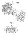
- the holder consists of a carrier 1 for receiving an optical element 2 designed here, for example, as a deflection prism, and a clamping element 3 which clamps the optical element in the carrier.
- the carrier 1 is circular and pot-shaped here and is, for example, part of a housing for an optical resonator, for example a gas laser.
- the bottom 4 of the carrier is formed with a here-rectangular opening 5 for the beam path and provided on its inside for receiving the optical element 2 with an essentially likewise rectangular cut-out 6 with rounded corners.
- Two opposite side walls 7, 8 of the cutout 6 are set back in their length in a partial area 10 corresponding to the height h of the rectangular base 9 of the optical element, so that steps 11 are formed.
- the recessed partial areas 10 delimit with their end face 14 and the steps 11 a surface corresponding to the rectangular base area 9 of the optical element, so that the optical element used in the cutout 6 has a positive fit through the end faces 14 and the steps 11 and laterally with sufficient accuracy is fixed in its position. Since the rectangular base 9 of the optical element has sharp-edged corners, recesses 12 are provided between the end faces 14 and the corresponding steps 11 in the manner shown in FIG. 1, which form webs 13 which are set back with the end face 14 relative to the side walls 7, 8 of the cutout .
- the base 15 is formed with three raised, finely machined support points 16, 17 and 18, which are arranged here lying on the edge of the opening 5 at the corners of an isosceles triangle.
- the support points 16 and 17 are located on the parallel longitudinal sides 19 and 20 of the opening 5, while the third support point 18 is arranged on the one narrow side 21 of the opening. In this way, the position of the optical element relative to the beam path is determined with high accuracy.
- the carrier 1 used to hold the optical element and its holder has a circumferential, inwardly directed edge 22 on its free end face, ie opposite the bottom 4, both the edge and the wall 23 of the support itself having depressions on the inside 24 is provided, which start from the free end face and are therefore accessible from this and extend in the direction of the central axis 25 of the carrier.
- the edge 22 forms an undercut 26 at the transition to the wall 23, which serves to support the clamping element 3.
- the clamping element consists of a spring of U-shaped cross section with spring legs and a base enclosed between them.
- the spring consists of a cup-shaped circular part, the outer diameter of which is adapted to the inner diameter of the carrier.
- the lateral surface 27 of the spring 3 runs conically to the spring base 28 and is with several Ren, preferably uniformly arranged on the circumference and parallel slots 29 in the direction of the central axis 25 divided into individual spring legs 30, the height B is approximately equal to or less than the distance a between the undercut 26 and the inside 31 of the support base 4.
- the spring base 28 is provided with an essentially rectangular knockout 32, on the narrow sides of which two mutually aligned spring tabs 34 formed by slots 33 are provided.
- the spring legs 30 When the spring 3 is inserted into the chamber 35, the spring legs 30 snap into the undercut 26 behind the edge 22 of the carrier.
- the spring tabs 34 of the spring base are bent up - on the optical element, ie, abutting its side surfaces 36 - and then press the optical element with their prestressing force against the support points 16, 17 and 18. Now the optical element is also fixed in the direction of its optical axis .
- the depressions 24, which are located on the circumference of the chamber 35 behind each spring leg 30 but are only shown in small numbers in FIG. 1, are provided, in which a suitably designed tool can engage. With the tool, the spring legs 30 are pressed inwards so that the spring 3 can be removed from the chamber 35.
- an end plate which is not shown in more detail here, may first have to be removed, which can be provided in a holder according to the invention, in particular when the requirements for the purity of the surroundings of the optical element are high, for closing the chamber 35 in a vacuum-tight manner.
- the end plate can be attached to the edge 22 of the carrier, for example by welding.
- optical elements other than the one shown for example a flat mirror, can also be clamped in the carrier.
- the illustrated embodiment of a pot spring can also be used for a flat mirror.
- leg springs are also conceivable, which are then suitably U-shaped in cross-section depending on the optical element.
Landscapes
- Physics & Mathematics (AREA)
- General Physics & Mathematics (AREA)
- Optics & Photonics (AREA)
- Mounting And Adjusting Of Optical Elements (AREA)
- Optical Couplings Of Light Guides (AREA)
- Led Device Packages (AREA)
- Lasers (AREA)
Applications Claiming Priority (2)
| Application Number | Priority Date | Filing Date | Title |
|---|---|---|---|
| DE3415853 | 1984-04-27 | ||
| DE3415853 | 1984-04-27 |
Publications (2)
| Publication Number | Publication Date |
|---|---|
| EP0162961A2 true EP0162961A2 (fr) | 1985-12-04 |
| EP0162961A3 EP0162961A3 (fr) | 1988-03-02 |
Family
ID=6234570
Family Applications (1)
| Application Number | Title | Priority Date | Filing Date |
|---|---|---|---|
| EP84115420A Withdrawn EP0162961A3 (fr) | 1984-04-27 | 1984-12-14 | Fixage d'un élément optique |
Country Status (4)
| Country | Link |
|---|---|
| US (1) | US4600272A (fr) |
| EP (1) | EP0162961A3 (fr) |
| JP (1) | JPS60243621A (fr) |
| NO (1) | NO851490L (fr) |
Cited By (1)
| Publication number | Priority date | Publication date | Assignee | Title |
|---|---|---|---|---|
| FR2688321A1 (fr) * | 1992-03-04 | 1993-09-10 | Diehl Gmbh & Co | Miroir deformable. |
Families Citing this family (8)
| Publication number | Priority date | Publication date | Assignee | Title |
|---|---|---|---|---|
| DE8625896U1 (fr) * | 1986-09-27 | 1986-11-13 | Fa. Carl Zeiss, 7920 Heidenheim, De | |
| GB9210488D0 (en) * | 1992-05-15 | 1992-07-01 | British Tech Group | Mechanical mounting |
| JP3070429B2 (ja) * | 1995-01-19 | 2000-07-31 | キヤノン株式会社 | 双眼鏡 |
| US5737346A (en) * | 1996-07-01 | 1998-04-07 | Hughes Electronics | Mount for optical components |
| US6061190A (en) * | 1999-03-11 | 2000-05-09 | Optics For Research | Devices for holding optical components at fixed positions |
| US8270100B2 (en) * | 2009-11-03 | 2012-09-18 | Honeywell International Inc. | Optical component design for silicon optical bench |
| RU2594636C1 (ru) * | 2015-07-14 | 2016-08-20 | Акционерное общество "Научно-производственная корпорация "Системы прецизионного приборостроения" (АО "НПК "СПП") | Устройство световозвращающее |
| TWI597536B (zh) * | 2016-10-27 | 2017-09-01 | 財團法人國家實驗硏究院 | 用於支撐鏡片的支撐裝置與方法及用於支 撐功能元件的支撐組件 |
Citations (5)
| Publication number | Priority date | Publication date | Assignee | Title |
|---|---|---|---|---|
| DE281626C (fr) * | ||||
| US2435908A (en) * | 1944-01-05 | 1948-02-10 | Tinnerman Products Inc | Fastening device |
| US3865472A (en) * | 1968-11-22 | 1975-02-11 | J Hobarth | Mirror mount for a laser |
| GB1578354A (en) * | 1977-04-02 | 1980-11-05 | Hamar M | Optical assembly including a laser tube |
| EP0067405A2 (fr) * | 1981-06-11 | 1982-12-22 | Wild Heerbrugg Ag. | Support pour un élément optique prismatique |
Family Cites Families (6)
| Publication number | Priority date | Publication date | Assignee | Title |
|---|---|---|---|---|
| DE285116C (fr) * | ||||
| US1285775A (en) * | 1917-08-04 | 1918-11-26 | Crown Optical Co | Optical instrument. |
| US2477705A (en) * | 1945-05-16 | 1949-08-02 | Tinnerman Products Inc | Instrument housing and closure fastening device therefor |
| US2552938A (en) * | 1947-02-06 | 1951-05-15 | Cojan Jean | Means for securing optical elements |
| US2780142A (en) * | 1954-05-06 | 1957-02-05 | Optische Ind De Oude Delft Nv | Cylindrically reflecting mirror-prism anamorphotic optical system |
| DE3130420C2 (de) * | 1981-07-31 | 1986-12-18 | Siemens AG, 1000 Berlin und 8000 München | Justiervorrichtung für ein in einem Träger angeordnetes optisches Element einer optischen Anordnung |
-
1984
- 1984-12-14 EP EP84115420A patent/EP0162961A3/fr not_active Withdrawn
-
1985
- 1985-03-21 US US06/714,403 patent/US4600272A/en not_active Expired - Fee Related
- 1985-04-15 NO NO851490A patent/NO851490L/no unknown
- 1985-04-25 JP JP60087663A patent/JPS60243621A/ja active Pending
Patent Citations (5)
| Publication number | Priority date | Publication date | Assignee | Title |
|---|---|---|---|---|
| DE281626C (fr) * | ||||
| US2435908A (en) * | 1944-01-05 | 1948-02-10 | Tinnerman Products Inc | Fastening device |
| US3865472A (en) * | 1968-11-22 | 1975-02-11 | J Hobarth | Mirror mount for a laser |
| GB1578354A (en) * | 1977-04-02 | 1980-11-05 | Hamar M | Optical assembly including a laser tube |
| EP0067405A2 (fr) * | 1981-06-11 | 1982-12-22 | Wild Heerbrugg Ag. | Support pour un élément optique prismatique |
Cited By (1)
| Publication number | Priority date | Publication date | Assignee | Title |
|---|---|---|---|---|
| FR2688321A1 (fr) * | 1992-03-04 | 1993-09-10 | Diehl Gmbh & Co | Miroir deformable. |
Also Published As
| Publication number | Publication date |
|---|---|
| JPS60243621A (ja) | 1985-12-03 |
| NO851490L (no) | 1985-10-28 |
| EP0162961A3 (fr) | 1988-03-02 |
| US4600272A (en) | 1986-07-15 |
Similar Documents
| Publication | Publication Date | Title |
|---|---|---|
| DE4329824A1 (de) | Adapter für ein optisches Verbindungsglied und Schaltplattenanschlußstück für denselben | |
| EP0162961A2 (fr) | Fixage d'un élément optique | |
| DE1283941B (de) | Vorrichtung zur Aufnahme von elektrischen Bauelementen | |
| DE1529646C3 (de) | Regal | |
| EP0485832A2 (fr) | Ensemble projecteur pour véhicules | |
| DE2735825C2 (fr) | ||
| CH652269A5 (en) | Quick mounting base made of plastic, for fixing an electrical device or printed-circuit board | |
| EP0148334A2 (fr) | Dispositif pour la fixation d'accessoires sur la paroi d'une armature lumineuse | |
| EP0469284B1 (fr) | Elément de montage | |
| DE8413064U1 (de) | Halterung für ein optisches Element | |
| EP0701091A1 (fr) | Support de lampe à introduire dans un corps de lampe | |
| EP0150744B1 (fr) | Haut-parleur | |
| EP0208129A2 (fr) | Boîtier de protection | |
| EP0550839B1 (fr) | Boîte de jonction en forme de caisson pour câble électronique | |
| DE2626500C2 (de) | Zierleistenklammer, insbesondere für schwere und breite Zierleisten zur Befestigung an den Karosseriewänden von Omnibussen und Lastkraftwagen | |
| EP0156291A2 (fr) | Lampe compacte fluorescente | |
| EP0813010B1 (fr) | Calotte en matière plastique | |
| CH657480A5 (de) | Vorrichtung zum festklemmen elektrischer leiter, insbesondere von draehten. | |
| DE2618355C2 (de) | Vorsatzteil einer Strahlerleuchte | |
| EP0011131B1 (fr) | Appareil d'installation à couvercle sans vis | |
| AT379227B (de) | Leuchte fuer leuchtstofflampen | |
| CH646014A5 (de) | Gasentladungslaser. | |
| EP0268234B1 (fr) | Fixage pour élément optique | |
| DE4102844C1 (en) | Electrical plug contact element - has auxiliary spring elements attached to rectangular base part with arms applying pressure on contact region | |
| DE4036737C2 (de) | Lageraufnahme zum spielfreien Einbau in ein Gehäuse |
Legal Events
| Date | Code | Title | Description |
|---|---|---|---|
| PUAI | Public reference made under article 153(3) epc to a published international application that has entered the european phase |
Free format text: ORIGINAL CODE: 0009012 |
|
| 17P | Request for examination filed |
Effective date: 19841221 |
|
| AK | Designated contracting states |
Designated state(s): AT BE CH DE FR GB IT LI LU NL SE |
|
| PUAL | Search report despatched |
Free format text: ORIGINAL CODE: 0009013 |
|
| AK | Designated contracting states |
Kind code of ref document: A3 Designated state(s): AT BE CH DE FR GB IT LI LU NL SE |
|
| STAA | Information on the status of an ep patent application or granted ep patent |
Free format text: STATUS: THE APPLICATION IS DEEMED TO BE WITHDRAWN |
|
| 18D | Application deemed to be withdrawn |
Effective date: 19880903 |
|
| RIN1 | Information on inventor provided before grant (corrected) |
Inventor name: HABENSCHADEN, K.,DIPL.-ING.(FH) Inventor name: WASNER, GUENTER Inventor name: KREUTZER, HANS, DIPL.-ING.(FH) Inventor name: DOST, WILLIBALD, DIPL.-ING.(FH) |