EP0162961A2 - Mounting for an optical element - Google Patents
Mounting for an optical element Download PDFInfo
- Publication number
- EP0162961A2 EP0162961A2 EP84115420A EP84115420A EP0162961A2 EP 0162961 A2 EP0162961 A2 EP 0162961A2 EP 84115420 A EP84115420 A EP 84115420A EP 84115420 A EP84115420 A EP 84115420A EP 0162961 A2 EP0162961 A2 EP 0162961A2
- Authority
- EP
- European Patent Office
- Prior art keywords
- spring
- optical element
- holder according
- carrier
- support
- Prior art date
- Legal status (The legal status is an assumption and is not a legal conclusion. Google has not performed a legal analysis and makes no representation as to the accuracy of the status listed.)
- Withdrawn
Links
Images
Classifications
-
- G—PHYSICS
- G02—OPTICS
- G02B—OPTICAL ELEMENTS, SYSTEMS OR APPARATUS
- G02B7/00—Mountings, adjusting means, or light-tight connections, for optical elements
- G02B7/18—Mountings, adjusting means, or light-tight connections, for optical elements for prisms; for mirrors
- G02B7/182—Mountings, adjusting means, or light-tight connections, for optical elements for prisms; for mirrors for mirrors
-
- G—PHYSICS
- G02—OPTICS
- G02B—OPTICAL ELEMENTS, SYSTEMS OR APPARATUS
- G02B7/00—Mountings, adjusting means, or light-tight connections, for optical elements
- G02B7/18—Mountings, adjusting means, or light-tight connections, for optical elements for prisms; for mirrors
- G02B7/1805—Mountings, adjusting means, or light-tight connections, for optical elements for prisms; for mirrors for prisms
Definitions
- the invention relates to a holder for an optical element that can be inserted into a beam path, e.g. a reflector mirror or a deflecting prism, in particular for an optical resonator, with a cup-shaped support, the bottom of which is formed with an opening for the beam path and on the inside with a cutout, the optical element being inserted laterally through the cutout wall and by means of a cutout into the support Clamping element is fixed in the direction of its optical axis.
- a beam path e.g. a reflector mirror or a deflecting prism, in particular for an optical resonator
- a cup-shaped support the bottom of which is formed with an opening for the beam path and on the inside with a cutout
- the optical element being inserted laterally through the cutout wall and by means of a cutout into the support
- Clamping element is fixed in the direction of its optical axis.
- Such a holder is known from DE-OS 31 30 420 for an optical element, in particular for a reflector mirror of a laser resonator.
- the optical element is easy to install and replace, and in many applications it is held sufficiently securely, but suitable pressing and sealing elements are still provided in the clamping area between the screw closure and the optical element.
- the holder is formed in several parts in the clamping area.
- brackets with screw connections, particularly in mobile use are at risk of loosening or even loosening sens exposed, so that a secure attachment of the optical element in the long term and also in mobile use is not always guaranteed.
- the invention is therefore based on the object of designing a holder of the type mentioned in such a way that, with easy dismantling and dismantling of the optical element, a simpler construction and regardless of the ambient and operating conditions, a universal usability of the holder and a permanently secure attachment of the optical element Element is given.
- a holder of the type mentioned according to the invention in that the support is provided in the region of its free end face at several points or continuously with an inward-facing edge forming an undercut, and in that the clamping element consists of a cross-section There is a U-shaped spring, the spring legs of which snap into the undercut and whose bottom, which is enclosed between the spring legs, bears against the optical element under prestress.
- the optical element received in the bottom cutout of the support and thereby laterally fixed with sufficient accuracy is fixed in the direction of its optical axis by means of a spring which is inserted into the chamber formed between the bottom and the edge of the support, so that the Snap the spring leg into the undercut.
- the spring base then presses the optical element against the support into the cutout with its pretensioning force.
- only a single clamping element in the form of a spring is required for fastening the optical element. This results in a simpler structure in the clamping area now one-piece bracket.
- the spring effects a permanently secure attachment of the optical element, which is also well suited for mobile use of an arrangement provided with the holder according to the invention.
- the spring is a clamp without screw, putty or adhesive connections, so that the holder according to the invention can also be used in the case of high cleanliness requirements for the surroundings of the optical element.
- the holder according to the invention can thus be used universally regardless of the ambient and operating conditions.
- a bracket with a spring as the only clamping element is also easy to assemble and disassemble.
- the spring consists of a cup-shaped part, the spring legs of which are formed by a plurality of slots on the circumference of the part.
- the spring is adapted to the shape of the carrier.
- the bottom of the spring is formed with a recess with at least two spring tabs each aligned with one another.
- the edge of the carrier and the carrier itself are formed on the inside with depressions accessible from the free end face.
- the spring legs can be easily pressed inwards using a suitably designed tool, so that the spring can be easily removed from the chamber.
- the carrier is sealed on the open side with an end plate to the outside. Such an end plate can advantageously be attached to the edge of the carrier by welding or soldering.
- the holder consists of a carrier 1 for receiving an optical element 2 designed here, for example, as a deflection prism, and a clamping element 3 which clamps the optical element in the carrier.
- the carrier 1 is circular and pot-shaped here and is, for example, part of a housing for an optical resonator, for example a gas laser.
- the bottom 4 of the carrier is formed with a here-rectangular opening 5 for the beam path and provided on its inside for receiving the optical element 2 with an essentially likewise rectangular cut-out 6 with rounded corners.
- Two opposite side walls 7, 8 of the cutout 6 are set back in their length in a partial area 10 corresponding to the height h of the rectangular base 9 of the optical element, so that steps 11 are formed.
- the recessed partial areas 10 delimit with their end face 14 and the steps 11 a surface corresponding to the rectangular base area 9 of the optical element, so that the optical element used in the cutout 6 has a positive fit through the end faces 14 and the steps 11 and laterally with sufficient accuracy is fixed in its position. Since the rectangular base 9 of the optical element has sharp-edged corners, recesses 12 are provided between the end faces 14 and the corresponding steps 11 in the manner shown in FIG. 1, which form webs 13 which are set back with the end face 14 relative to the side walls 7, 8 of the cutout .
- the base 15 is formed with three raised, finely machined support points 16, 17 and 18, which are arranged here lying on the edge of the opening 5 at the corners of an isosceles triangle.
- the support points 16 and 17 are located on the parallel longitudinal sides 19 and 20 of the opening 5, while the third support point 18 is arranged on the one narrow side 21 of the opening. In this way, the position of the optical element relative to the beam path is determined with high accuracy.
- the carrier 1 used to hold the optical element and its holder has a circumferential, inwardly directed edge 22 on its free end face, ie opposite the bottom 4, both the edge and the wall 23 of the support itself having depressions on the inside 24 is provided, which start from the free end face and are therefore accessible from this and extend in the direction of the central axis 25 of the carrier.
- the edge 22 forms an undercut 26 at the transition to the wall 23, which serves to support the clamping element 3.
- the clamping element consists of a spring of U-shaped cross section with spring legs and a base enclosed between them.
- the spring consists of a cup-shaped circular part, the outer diameter of which is adapted to the inner diameter of the carrier.
- the lateral surface 27 of the spring 3 runs conically to the spring base 28 and is with several Ren, preferably uniformly arranged on the circumference and parallel slots 29 in the direction of the central axis 25 divided into individual spring legs 30, the height B is approximately equal to or less than the distance a between the undercut 26 and the inside 31 of the support base 4.
- the spring base 28 is provided with an essentially rectangular knockout 32, on the narrow sides of which two mutually aligned spring tabs 34 formed by slots 33 are provided.
- the spring legs 30 When the spring 3 is inserted into the chamber 35, the spring legs 30 snap into the undercut 26 behind the edge 22 of the carrier.
- the spring tabs 34 of the spring base are bent up - on the optical element, ie, abutting its side surfaces 36 - and then press the optical element with their prestressing force against the support points 16, 17 and 18. Now the optical element is also fixed in the direction of its optical axis .
- the depressions 24, which are located on the circumference of the chamber 35 behind each spring leg 30 but are only shown in small numbers in FIG. 1, are provided, in which a suitably designed tool can engage. With the tool, the spring legs 30 are pressed inwards so that the spring 3 can be removed from the chamber 35.
- an end plate which is not shown in more detail here, may first have to be removed, which can be provided in a holder according to the invention, in particular when the requirements for the purity of the surroundings of the optical element are high, for closing the chamber 35 in a vacuum-tight manner.
- the end plate can be attached to the edge 22 of the carrier, for example by welding.
- optical elements other than the one shown for example a flat mirror, can also be clamped in the carrier.
- the illustrated embodiment of a pot spring can also be used for a flat mirror.
- leg springs are also conceivable, which are then suitably U-shaped in cross-section depending on the optical element.
Abstract
Zur einfachen, dauerhaft sicheren Befestigung eines optischen Elementes (2), z.B. eines Reflektorspiegels, ohne Beeinträchtigung der Reinheit seiner Umgebung, ist ein topfförmiger Träger (1) vorgesehen, in dessen Ausschnitt (6) das optische Element durch formschlüssige Aufnahme seitlich fixiert ist, wobei als Klemmelement eine in den Träger einrastende Schenkelfeder (3) vorgesehen ist, welche unter Vorspannung an dem optischen Element anliegt. Damit wird eine schraubenlose, kitt- und klebfreie Klemmung erzielt. Die Erfindung ist allgemein zur Befestigung von optischen Elementen, insbesondere eines Spiegels oder eines Umkehrprismas bei einem optischen Resonator, geeignet.For simple, permanently secure attachment of an optical element (2), e.g. of a reflector mirror, without impairing the purity of its surroundings, a cup-shaped support (1) is provided, in the cutout (6) of which the optical element is laterally fixed by a form-fitting receptacle, a leg spring (3) engaging in the support being provided as the clamping element, which bears against the optical element under prestress. This enables screwless, putty-free and tack-free clamping. The invention is generally suitable for fastening optical elements, in particular a mirror or a reversing prism in an optical resonator.
Description
Die Erfindung betrifft eine Halterung für ein in einen Strahlengang einfügbares optisches Element, z.B. einen Reflektorspiegel oder ein Umlenkprisma, insbesondere für einen optischen Resonator, mit einem topfförmigen Träger, dessen Boden mit einem Durchbruch für den Strahlengang und an der Innenseite mit einem Ausschnitt ausgebildet ist, wobei das optische Element durch die Ausschnittwandung seitlich und mittels eines in den Träger einsetzbaren Klemmelementes in Richtung seiner optischen Achse fixiert ist.The invention relates to a holder for an optical element that can be inserted into a beam path, e.g. a reflector mirror or a deflecting prism, in particular for an optical resonator, with a cup-shaped support, the bottom of which is formed with an opening for the beam path and on the inside with a cutout, the optical element being inserted laterally through the cutout wall and by means of a cutout into the support Clamping element is fixed in the direction of its optical axis.
Eine derartige Halterung ist aus der DE-OS 31 30 420 für ein optisches Element, insbesondere für einen Reflektorspiegel eines Laserresonators,bekannt. Bei dieser Halterung ist das optische Element zwar leicht montierbar und auswechselbar sowie in vielen Anwendungsfällen ausreichend sicher gehalten, jedoch sind im Klemmbereich zwischen dem Schraubverschluß und dem optischen Element noch geeignete Andrück- und Dichtungselemente vorgesehen. Dadurch ist d.ie Halterung im Klemmbereich mehrteilig ausgebildet. Außerdem ist bei Halterungen, deren Klemmung eine Schraubverbindung oder zum Beispiel eine Klebe- oder Kittverbindung aufweist, die Gefahr einer Verunreinigung der Umgebung des optischen Elementes gegeben, so daß derartige Halterungen für bestimmte Anwendungsfälle, in denen eine unbedingte Reinhaltung der Umgebung des optischen Elementes erforderlich ist, wie z.B. bei Gaslasern, weniger gut geeignet sind. Ferner sind Halterungen mit Schraubverbindungen insbesondere im mobilen Einsatz der Gefahr der Lockerung oder gar des Lösens ausgesetzt, so daß eine auf Dauer und auch im mobilen Einsatz sichere Befestigung des optischen Elementes nicht immer gewährleistet ist.Such a holder is known from DE-OS 31 30 420 for an optical element, in particular for a reflector mirror of a laser resonator. With this holder, the optical element is easy to install and replace, and in many applications it is held sufficiently securely, but suitable pressing and sealing elements are still provided in the clamping area between the screw closure and the optical element. As a result, the holder is formed in several parts in the clamping area. In addition, there is a risk of contamination of the surroundings of the optical element in brackets, the clamping of which has a screw connection or, for example, an adhesive or putty connection, so that such brackets for certain applications in which an unconditional keeping of the environment of the optical element is required , such as with gas lasers, are less suitable. Furthermore, brackets with screw connections, particularly in mobile use, are at risk of loosening or even loosening sens exposed, so that a secure attachment of the optical element in the long term and also in mobile use is not always guaranteed.
Der Erfindung liegt daher die Aufgabe zugrunde, eine Halterung der eingangs genannten Art so auszubilden, daß bei leichter Hontier- und Demontierbarkeit des optischen Elementes ein einfacherer Aufbau und unabhängig von den Umgebungs- und Einsatzbedingungen eine universelle Verwendbarkeit der Halterung sowie eine dauerhaft sichere Befestigung des optischen Elementes gegeben ist.The invention is therefore based on the object of designing a holder of the type mentioned in such a way that, with easy dismantling and dismantling of the optical element, a simpler construction and regardless of the ambient and operating conditions, a universal usability of the holder and a permanently secure attachment of the optical element Element is given.
Diese Aufgabe wird bei einer Halterung der eingangs genannten Art gemäß der Erfindung dadurch gelöst, daß der Träger in Bereich seiner freien Stirnseite an mehreren Stellen oder unlaufend mit einem nach innen gerichteten, eine Hinterschneidung bildenden Rand versehen ist, und daß das Klemmelement aus einer im Querschnitt U-förmigen Feder besteht, deren Federschenkel in die Hinterschneidung einrasten und deren zwischen den Federschenkeln eingeschlossener Boden unter Vorspannung an dem optischen Element anliegt.This object is achieved in a holder of the type mentioned according to the invention in that the support is provided in the region of its free end face at several points or continuously with an inward-facing edge forming an undercut, and in that the clamping element consists of a cross-section There is a U-shaped spring, the spring legs of which snap into the undercut and whose bottom, which is enclosed between the spring legs, bears against the optical element under prestress.
Bei einer erfindungsgemäßen Halterung ist das im Bodenausschnitt des Trägers formschlüssig aufgenommene und dadurch mit ausreichender Genauigkeit seitlich fixierte optische Element in Richtung seiner optischen Achse mittels einer Feder fixiert, welche in die zwischen dem Boden und dem Rand des Trägers gebildete Kammer eingeschoben wird, so daß die Federschenkel in die Hinterschneidung einrasten. Der Federboden drückt dann mit seiner Vorspannkraft das optische Element gegen die Auflage in den Ausschnitt. Zur Befestigung des optischen Elementes ist somit neben der besonderen Gestaltung des Trägers lediglich ein einziges Klemmelement in Form einer Feder erforderlich. Damit ergibt sich ein einfacherer Aufbau der im Klemmbereich nunmehr einteilig ausführbaren Halterung. Die Feder bewirkt eine dauerhaft sichere Befestigung des optischen Elementes, die auch für den mobilen Einsatz einer mit der erfindungsgemäßen Halterung versehenen Anordnung gut geeignet ist. Darüber hinaus stellt die Feder eine Klemmung ohne Schraub-, Kittoder Klebverbindungen dar, so daß die erfindungsgemäße Halterung auch bei hohen Reinhaltungsforderungen an die Umgebung des optischen Elementes einsatzfähig ist. Damit ist die erfindungsgemäße Halterung unabhängig von den Umgebungsund Einsatzbedingungen universell verwendbar. Eine Halterung mit einer Feder als einzigem Klemmelement ist außerdem leicht montier- und demontierbar.In a holder according to the invention, the optical element received in the bottom cutout of the support and thereby laterally fixed with sufficient accuracy is fixed in the direction of its optical axis by means of a spring which is inserted into the chamber formed between the bottom and the edge of the support, so that the Snap the spring leg into the undercut. The spring base then presses the optical element against the support into the cutout with its pretensioning force. In addition to the special design of the carrier, only a single clamping element in the form of a spring is required for fastening the optical element. This results in a simpler structure in the clamping area now one-piece bracket. The spring effects a permanently secure attachment of the optical element, which is also well suited for mobile use of an arrangement provided with the holder according to the invention. In addition, the spring is a clamp without screw, putty or adhesive connections, so that the holder according to the invention can also be used in the case of high cleanliness requirements for the surroundings of the optical element. The holder according to the invention can thus be used universally regardless of the ambient and operating conditions. A bracket with a spring as the only clamping element is also easy to assemble and disassemble.
Bei einer vorteilhaften Ausführungsform einer erfindungsgemäßen Halterung besteht die Feder aus einem topfförmig gestalteten Teil, dessen Federschenkel durch mehrere Schlitze am Umfang des Teiles gebildet sind. Dadurch ist die Feder der Form des Trägers angepaßt.In an advantageous embodiment of a holder according to the invention, the spring consists of a cup-shaped part, the spring legs of which are formed by a plurality of slots on the circumference of the part. As a result, the spring is adapted to the shape of the carrier.
Um bei einer erfindungsgemäßen Halterung eine möglichst große Klemmwirkung der Feder zu erzielen, ist es vorteilhaft, wenn der Boden der Feder mit einer Ausnehmung mit mindestens jeweils zwei zueinander fluchtenden Federlappen ausgebildet ist.In order to achieve the greatest possible clamping effect of the spring in a holder according to the invention, it is advantageous if the bottom of the spring is formed with a recess with at least two spring tabs each aligned with one another.
Zur Erleichterung der Demontage ist es bei einer erfindungsgemäßen Halterung zweckmäßig, wenn der Rand des Trägers und der Träger selbst an der Innenseite mit von der freien Stirnseite her zugänglichen Vertiefungen ausgebildet sind. Dadurch können die Federschenkel mit einem entsprechend ausgebildeten Werkzeug ohne weiteres nach innen gedrückt werden, so daß die Feder leicht aus der Kammer entnommen werden kann. Hinsichtlich des Einsatzes der erfindungsgemäßen Halterung, insbesondere bei hohen Reinhaltungsforderungen, ist es zweckmäßig, wenn der Träger an der offenen Seite mit einer Abschlußplatte nach außen abgedichtet ist. Eine derartige Abschlußplatte kann in vorteilhafter Weise durch Schweißen oder Löten an dem Rand des Trägers befestigt werden.To facilitate dismantling, it is expedient in a holder according to the invention if the edge of the carrier and the carrier itself are formed on the inside with depressions accessible from the free end face. As a result, the spring legs can be easily pressed inwards using a suitably designed tool, so that the spring can be easily removed from the chamber. With regard to the use of the holder according to the invention, particularly in the case of high cleanliness requirements, it is expedient if the carrier is sealed on the open side with an end plate to the outside. Such an end plate can advantageously be attached to the edge of the carrier by welding or soldering.
Ein Ausführungsbeispiel einer erfindungsgemäßen Halterung ist in folgenden anhand der Zeichnung näher beschrieben.
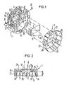
- Fig. 1 zeigt die Halterung mit ihren Einzelteilen in explosionsartiger, perspektivischer Darstellung,
- Fig. 2 zeigt einen Schnitt II-II nach Fig.1.
- 1 shows the holder with its individual parts in an exploded, perspective view,
- Fig. 2 shows a section II-II of Fig.1.
Die Halterung besteht aus einem Träger 1 zur Aufnahme eines hier beispielsweise als Umlenkprisma ausgebildeten optischen Elementes 2 sowie aus eines Klemmelement 3, welches das optische Element in dem Träger festklemmt. Der Träger 1 ist hier kreisrund und topfförmig ausgebildet und z.B. Bestandteil eines Gehäuses für einen optischen Resonator, z.B. eines Gaslasers. Der Boden 4 des Trägers ist mit einem hier-rechteckförmigen Durchbruch 5 für den Strahlengang ausgebildet und an seiner Innenseite zur Aufnahme des optischen Elementes 2 mit einem im wesentlichen ebenfalls rechteckförmigen Ausschnitt 6 mit abgerundeten Ecken versehen. Zwei einander gegenüberliegende Seitenwände 7,8 des Ausschnitts 6 sind in einem der Höhe h der rechteckigen Grundfläche 9 des optischen Elementes entsprechenden Teilbereich 10 ihrer Länge so zurückversetzt, daß Stufen 11 gebildet sind. Damit umgrenzen die zurückversetzten Teilbereiche 10 mit ihrer Stirnfläche 14 und die Stufen 11 eine der rechteckigen Grundfläche 9 des optischen Elementes entsprechende Fläche, so daß das in den Ausschnitt 6 eingesetzte optische Element durch die Stirnflächen 14 und die Stufen 11 formschlüssig umfaßt und mit ausreichender Genauigkeit seitlich in seiner Lage fixiert ist. Da die rechteckige Grundfläche 9 des optischen Elementes scharfkantige Ecken aufweist, sind zwischen den Stirnflächen 14 und den entsprechenden Stufen 11 noch Ausnehmungen 12 in der aus Fig. 1 ersichtlichen Weise vorgesehen, die Stege 13 bilden, welche mit der Stirnfläche 14 gegenüber den Seitenwänden 7,8 des Ausschnitts zurückversetzt sind. Zur Auflage der rechteckigen Grundfläche 9 des optischen Elementes 2 in dem Ausschnitt 6 ist dessen Grundfläche 15 mit drei erhabenen, feinbearbeiteten Auflagestellen 16,17 und 18 ausgebildet, die hier am Rand des Durchbruchs 5 an den Ecken eines gleichschenkligen Dreiecks liegend angeordnet sind. Dabei liegen sich die Auflagestellen 16 und 17 an den parallelen Längsseiten 19 und 20 des Durchbruchs 5 gegenüber, während die dritte Auflagestelle 18 an der einen Schmalseite 21 des Durchbruchs angeordnet ist. Auf diese Weise ist die Lage des optischen Elementes zum Strahlengang mit hoher Genauigkeit bestimmt.The holder consists of a carrier 1 for receiving an
Der zur Aufnahme des optischen Elementes und dessen Halterung dienende Träger 1 weist an seiner freien, d.h. dem Boden 4 gegenüberliegenden Stirnseite einen umlaufenden, nach innen gerichteten Rand 22 auf, wobei sowohl der Rand als auch die Wandung 23 des Trägers selbst an der Innenseite mit Vertiefungen 24 versehen ist, die von der freien Stirnseite ausgehen und daher von dieser her zugänglich sind und sich in Richtung der Mittelachse 25 des Trägers erstrecken. Der Rand 22 bildet am Übergang zur Wandung 23 eine Hinterschneidung 26, welche zur Lagerung des Klemmelementes 3 dient. Das Klemmelement besteht bei der erfindungsgemäßen Halterung aus einer im Querschnitt U-förmigen Feder mit Federschenkeln und dazwischen eingeschlossenem Boden. Bei dem dargestellten Ausführungsbeispiel besteht die Feder aus einem topfförmig gestalteten kreisrunden Teil, dessen Außendurchmesser dem Innendurchmesser des Trägers angepaßt ist. Die Mantelfläche 27 der Feder 3 verläuft zum Federboden 28 kegelförmig und ist mit mehreren, am Umfang vorzugsweise gleichmäßig angeordneten und zueinander parallelen Schlitzen 29 in Richtung der Mittelachse 25 in einzelne Federschenkel 30 aufgeteilt, deren Höhe B etwa gleich oder kleiner den Abstand a zwischen der Hinterschneidung 26 und der Innenseite 31 des Trägerbodens 4 ist. Der Federboden 28 ist mit einer im wesentlichen rechteckigen Aasnehnung 32 versehen, an deren Schmalseiten zwei zueinander fluchtende, durch Schlitze 33 gebildete Federlappen 34 vorgesehen sind. Zur Festklemmung des optischen Elementes 2 in dem Ausschnitt 6 des Trägers 1 wird die Feder 3 lagerichtig, d.h. so in die zwischen dem Boden 4 des Trägers und dem Rand 22 gebildete Kammer 35 eingeschoben, daß sich der Durchbruch 5 des Trägers und die Ausnehmung 32 der Feder decken. Beim Einschieben der Feder 3 in die Kammer 35 rasten die Federschenkel 30 in die Hinterschneidung 26 hinter dem Rand 22 des Trägers ein. Die Federlappen 34 des Federbodens werden dabei - am optischen Element, d.h. an dessen Seitenflächen 36 anliegend - aufgebogen und drücken dann mit ihrer Vorspannkraft das optische Element gegen die Auflagestellen 16, 17 und 18. Nunmehr ist das optische Element auch in Richtung seiner optischen Achse fixiert. Zum Lösen der Klemmung zwecks Demontage des optischen Elementes sind die sich am Umfang der Kammer 35 hinter jedem Federschenkel 30 befindlichen, in Fig. 1 jedoch nur in geringerer Stückzahl eingezeichneten Vertiefungen 24 vorgesehen, in die ein entsprechend ausgebildetes Werkzeug eingreifen kann. Mit dem Werkzeug werden die Federschenkel 30 nach innen gedrückt, so daß die Feder 3 aus der Kammer 35 entnommen werden kann. Hierzu muß gegebenenfalls erst noch eine hier nicht näher dargestellte Abschlußplatte entfernt werden, welche bei einer erfindungsgemäßen Halterung, insbesondere bei hohen Anforderungen an die Reinheit der Umgebung des optischen Elementes, zum vakuundichten Verschließen der Kammer 35 vorgesehen werden kann. Die Abschlußplatte kann z.B. durch Scnweißen am Rand 22 des Trägers befestigt werden. Mit einer erfindungsgemäßen Halterung können auch andere optische Elemente als das dargestellte, z.B. ebene Spiegel, in dem Träger festgeklemmt werden. Die dargestellte Ausführungsform einer Topffeder kann dabei auch für einen ebenen Spiegel eingesetzt werden. Es sind aber auch andere Gestaltungen von Schenkelfedern denkbar, die dann abhängig vom optischen Element in geeigneter Weise im Querschnitt U-förmig ausgebildet werden.The carrier 1 used to hold the optical element and its holder has a circumferential, inwardly directed edge 22 on its free end face, ie opposite the bottom 4, both the edge and the
Claims (9)
Applications Claiming Priority (2)
| Application Number | Priority Date | Filing Date | Title |
|---|---|---|---|
| DE3415853 | 1984-04-27 | ||
| DE3415853 | 1984-04-27 |
Publications (2)
| Publication Number | Publication Date |
|---|---|
| EP0162961A2 true EP0162961A2 (en) | 1985-12-04 |
| EP0162961A3 EP0162961A3 (en) | 1988-03-02 |
Family
ID=6234570
Family Applications (1)
| Application Number | Title | Priority Date | Filing Date |
|---|---|---|---|
| EP84115420A Withdrawn EP0162961A3 (en) | 1984-04-27 | 1984-12-14 | Mounting for an optical element |
Country Status (4)
| Country | Link |
|---|---|
| US (1) | US4600272A (en) |
| EP (1) | EP0162961A3 (en) |
| JP (1) | JPS60243621A (en) |
| NO (1) | NO851490L (en) |
Cited By (1)
| Publication number | Priority date | Publication date | Assignee | Title |
|---|---|---|---|---|
| FR2688321A1 (en) * | 1992-03-04 | 1993-09-10 | Diehl Gmbh & Co | DEFORMABLE MIRROR. |
Families Citing this family (8)
| Publication number | Priority date | Publication date | Assignee | Title |
|---|---|---|---|---|
| DE8625896U1 (en) * | 1986-09-27 | 1986-11-13 | Fa. Carl Zeiss, 7920 Heidenheim, De | |
| GB9210488D0 (en) * | 1992-05-15 | 1992-07-01 | British Tech Group | Mechanical mounting |
| JP3070429B2 (en) * | 1995-01-19 | 2000-07-31 | キヤノン株式会社 | binoculars |
| US5737346A (en) * | 1996-07-01 | 1998-04-07 | Hughes Electronics | Mount for optical components |
| US6061190A (en) * | 1999-03-11 | 2000-05-09 | Optics For Research | Devices for holding optical components at fixed positions |
| US8270100B2 (en) * | 2009-11-03 | 2012-09-18 | Honeywell International Inc. | Optical component design for silicon optical bench |
| RU2594636C1 (en) * | 2015-07-14 | 2016-08-20 | Акционерное общество "Научно-производственная корпорация "Системы прецизионного приборостроения" (АО "НПК "СПП") | Retroreflective device |
| TWI597536B (en) * | 2016-10-27 | 2017-09-01 | 財團法人國家實驗硏究院 | Supporting device and method for supporting lens and supporting component for supporting functional element |
Citations (5)
| Publication number | Priority date | Publication date | Assignee | Title |
|---|---|---|---|---|
| DE281626C (en) * | ||||
| US2435908A (en) * | 1944-01-05 | 1948-02-10 | Tinnerman Products Inc | Fastening device |
| US3865472A (en) * | 1968-11-22 | 1975-02-11 | J Hobarth | Mirror mount for a laser |
| GB1578354A (en) * | 1977-04-02 | 1980-11-05 | Hamar M | Optical assembly including a laser tube |
| EP0067405A2 (en) * | 1981-06-11 | 1982-12-22 | Wild Heerbrugg Ag. | Support for a prismatic, optical element |
Family Cites Families (6)
| Publication number | Priority date | Publication date | Assignee | Title |
|---|---|---|---|---|
| DE285116C (en) * | ||||
| US1285775A (en) * | 1917-08-04 | 1918-11-26 | Crown Optical Co | Optical instrument. |
| US2477705A (en) * | 1945-05-16 | 1949-08-02 | Tinnerman Products Inc | Instrument housing and closure fastening device therefor |
| US2552938A (en) * | 1947-02-06 | 1951-05-15 | Cojan Jean | Means for securing optical elements |
| US2780142A (en) * | 1954-05-06 | 1957-02-05 | Optische Ind De Oude Delft Nv | Cylindrically reflecting mirror-prism anamorphotic optical system |
| DE3130420C2 (en) * | 1981-07-31 | 1986-12-18 | Siemens AG, 1000 Berlin und 8000 München | Adjusting device for an optical element of an optical arrangement arranged in a carrier |
-
1984
- 1984-12-14 EP EP84115420A patent/EP0162961A3/en not_active Withdrawn
-
1985
- 1985-03-21 US US06/714,403 patent/US4600272A/en not_active Expired - Fee Related
- 1985-04-15 NO NO851490A patent/NO851490L/en unknown
- 1985-04-25 JP JP60087663A patent/JPS60243621A/en active Pending
Patent Citations (5)
| Publication number | Priority date | Publication date | Assignee | Title |
|---|---|---|---|---|
| DE281626C (en) * | ||||
| US2435908A (en) * | 1944-01-05 | 1948-02-10 | Tinnerman Products Inc | Fastening device |
| US3865472A (en) * | 1968-11-22 | 1975-02-11 | J Hobarth | Mirror mount for a laser |
| GB1578354A (en) * | 1977-04-02 | 1980-11-05 | Hamar M | Optical assembly including a laser tube |
| EP0067405A2 (en) * | 1981-06-11 | 1982-12-22 | Wild Heerbrugg Ag. | Support for a prismatic, optical element |
Cited By (1)
| Publication number | Priority date | Publication date | Assignee | Title |
|---|---|---|---|---|
| FR2688321A1 (en) * | 1992-03-04 | 1993-09-10 | Diehl Gmbh & Co | DEFORMABLE MIRROR. |
Also Published As
| Publication number | Publication date |
|---|---|
| JPS60243621A (en) | 1985-12-03 |
| US4600272A (en) | 1986-07-15 |
| NO851490L (en) | 1985-10-28 |
| EP0162961A3 (en) | 1988-03-02 |
Similar Documents
| Publication | Publication Date | Title |
|---|---|---|
| EP1695525B1 (en) | Device for connecting a carrier part and an add-on piece | |
| DE4329824A1 (en) | Adaptor for optical fibre connection to circuit board - has two identical adaptor elements sandwiched about alignment sleeve contained in sleeve holder, and with snap fitting elements | |
| EP0162961A2 (en) | Mounting for an optical element | |
| DE1283941B (en) | Device for holding electrical components | |
| DE1529646C3 (en) | shelf | |
| EP0485832A2 (en) | Headlamp unit for vehicles | |
| DE2735825C2 (en) | ||
| DE2852829A1 (en) | QUICK-MOUNTED PLASTIC BASE | |
| EP0148334A2 (en) | Device for the attachment of accessories on the wall of a lighting fixture | |
| EP0469284B1 (en) | Mounting element | |
| DE8413064U1 (en) | Holder for an optical element | |
| EP0701091A1 (en) | Lampholder for mounting into the lamp casing | |
| EP0150744B1 (en) | Loudspeaker unit | |
| EP0208129A2 (en) | Protective casing | |
| EP0550839B1 (en) | Connection box for electrical cable | |
| DE2626500C2 (en) | Decorative strip clips, especially for heavy and wide decorative strips for attachment to the body walls of buses and trucks | |
| EP0156291A2 (en) | Compact fluorescent lamp | |
| EP0813010B1 (en) | Plastic cap | |
| CH657480A5 (en) | DEVICE FOR CLAMPING ELECTRICAL LADDER, ESPECIALLY OF WIRE. | |
| DE2618355C2 (en) | Attachment part of a spotlight | |
| EP0011131B1 (en) | Installation equipment with screwless cover | |
| AT379227B (en) | LAMP FOR FLUORESCENT LAMPS | |
| CH646014A5 (en) | GAS DISCHARGE LASER. | |
| EP0268234B1 (en) | Mounting for optical element | |
| DE4102844C1 (en) | Electrical plug contact element - has auxiliary spring elements attached to rectangular base part with arms applying pressure on contact region |
Legal Events
| Date | Code | Title | Description |
|---|---|---|---|
| PUAI | Public reference made under article 153(3) epc to a published international application that has entered the european phase |
Free format text: ORIGINAL CODE: 0009012 |
|
| 17P | Request for examination filed |
Effective date: 19841221 |
|
| AK | Designated contracting states |
Designated state(s): AT BE CH DE FR GB IT LI LU NL SE |
|
| PUAL | Search report despatched |
Free format text: ORIGINAL CODE: 0009013 |
|
| AK | Designated contracting states |
Kind code of ref document: A3 Designated state(s): AT BE CH DE FR GB IT LI LU NL SE |
|
| STAA | Information on the status of an ep patent application or granted ep patent |
Free format text: STATUS: THE APPLICATION IS DEEMED TO BE WITHDRAWN |
|
| 18D | Application deemed to be withdrawn |
Effective date: 19880903 |
|
| RIN1 | Information on inventor provided before grant (corrected) |
Inventor name: HABENSCHADEN, K.,DIPL.-ING.(FH) Inventor name: WASNER, GUENTER Inventor name: KREUTZER, HANS, DIPL.-ING.(FH) Inventor name: DOST, WILLIBALD, DIPL.-ING.(FH) |