EP0067405A2 - Support for a prismatic, optical element - Google Patents
Support for a prismatic, optical element Download PDFInfo
- Publication number
- EP0067405A2 EP0067405A2 EP82105021A EP82105021A EP0067405A2 EP 0067405 A2 EP0067405 A2 EP 0067405A2 EP 82105021 A EP82105021 A EP 82105021A EP 82105021 A EP82105021 A EP 82105021A EP 0067405 A2 EP0067405 A2 EP 0067405A2
- Authority
- EP
- European Patent Office
- Prior art keywords
- carrier
- optical component
- clamping means
- socket according
- prism
- Prior art date
- Legal status (The legal status is an assumption and is not a legal conclusion. Google has not performed a legal analysis and makes no representation as to the accuracy of the status listed.)
- Granted
Links
Images
Classifications
-
- G—PHYSICS
- G02—OPTICS
- G02B—OPTICAL ELEMENTS, SYSTEMS OR APPARATUS
- G02B7/00—Mountings, adjusting means, or light-tight connections, for optical elements
- G02B7/18—Mountings, adjusting means, or light-tight connections, for optical elements for prisms; for mirrors
- G02B7/1805—Mountings, adjusting means, or light-tight connections, for optical elements for prisms; for mirrors for prisms
Definitions
- the invention relates to the holder for a prismatic, optical component, with a carrier for receiving the optical component and clamping means.
- the prism is carried in the cylindrical support by adjusting screws and secured with adhesive.
- the carrier has at least one cylindrical surface section for receiving the optical component lying along two generators and that at least one one-part or multi-part clamping means which engages on the carrier is provided and which has at least one elastic element for achieving a contains statically determined storage with two clamping degrees of freedom of the optical component, whereby a self-alignment of the optical component is achieved.
- the carrier can be designed as a hollow cylinder for receiving a prismatic optical component in its interior with tangential planes in the contact generators, which have a larger opening angle than the tangential planes of the corresponding contact lines of the optical component.
- the carrier is advantageously a circular cylinder, so that it can be easily installed in an optical device so that it can be rotated about its axis.
- the one clamping means can also be fixed and the other releasably connected to the carrier, the releasable clamping means having at least one elastic element and the clamping means pressing the optical component against the carrier.
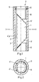
- Dove prism - 1 - (Fig. 1,2), which is preferably ground due to lower manufacturing costs and optically polished on the flat reflecting surface - 2 -, also for reasons of simpler, therefore cheaper, but also more precise manufacture , a circular cylindrical, very internally ground support - 3 -.
- the Dove prism lies on the inner surface of the carrier 3 along the prism edges 4 ′, 4 ′′ formed by the reflecting surface 2 with the cylinder jacket.
- On one end face 5 '- is the Dove prism - 1 - on a region of a ring-cylindrical clamping means - 6 - firmly connected to the support - 3 - on and on the other end face - 5 "- is a multi-part clamping means - 7 - with one region of its circular support element - 8 - on the Dove prism - 1 - on.
- This support element - 8 - is elastically countered by a ring - 9 - which can be screwed into the carrier - 3 - by means of an O-ring - 10 - located between the two the Dove prism - 1 - pressed.
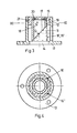
- a prism socket (Fig. 3,4) for a deflecting prism - 11 - has as a support - 12 - a tube which carries a flange - 13 - on one end face. This is used on the one hand as a fastening flange for the prism holder and on the other hand as a clamping means firmly connected to the tube, in that the inside diameter of the flange opening - 14 - is smaller than the diagonal of the surface of the deflecting prism - 11 - resting on it. As a result, the prism only rests on the flange in the area of its corners.
- This deflecting prism - 11 - is mounted in an annular-cylindrical sleeve - 15 - inserted in the tube by virtue of the fact that it has two of the edges - 16 ', 16 "- which are determined by the surfaces not resting on the flange, perpendicular to it rest on the inner cylinder surface, this sleeve being pierced in the area of the beam exit surface.
- the sleeve - 15 - is secured by a worm screw - 21 - which engages in a groove.
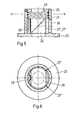
- a frame for another deflection prism (Fig. 5,6) is constructed similarly to the frame according to FIGS. 3 and 4.
- a circular-cylindrical carrier - 22 - which has a flange - 23 - with a circular opening - 24 -
- a two-part deflecting prism - 26 - is inserted so that it is on the one hand with the radiation entry surface, the one Diagonally larger than the diameter of the opening - 24 -, rests on the flange - 23 - and on the other hand with two contact edges - 27 ', 27 "- the beam exit surface rests against the inner wall of the sleeve first spring - 28 - pressed against the sleeve and held on the surface opposite the radiation entry surface by a second spring - 29 -, which rests on the corner regions of the prism, against the flange - 23 -, the second spring being held on a detachable retaining ring - 25 - supports.
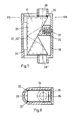
- a frame for a straight view prism - 31 - (Fig. 7,8) this lies with two support edges - 32 ', 32 "- the reflection surface - 33 - in a U-shaped support - 34 - in the region of the curvature and is held by a multi-part clamping means, which is essentially designed as a cover - 36 -
- an O-ring - 39 '- is arranged in the cover on one side, which lies against the prism and holds it axially.
- prism holders What is common to these prism holders is that the prism lies against a support along two support edges and is held in such a way that its support is statically determined and self-aligning, i.e. that there are two degrees of freedom of clamping.
- This type of frame is not limited to prisms. It can be used for all correspondingly shaped or mouldable optical components.
- the fixtures and gauges for adjustment and reworking are also omitted in this version.
- smaller frame dimensions are possible in comparable cases, and yet a higher level of insensitivity to impact, vibration and temperature stresses has been achieved, as tests have shown.
- the optically effective surface is always parallel to the mechanical frame axis, which often serves as the axis of rotation of the component. After the installation of the optical component, all adjustment work is no longer necessary; the accuracy is achieved through the individual processing of the individual parts and not, as was previously the case, through adjustment and rework.
Abstract
Description
Die Erfindung bezieht sich auf die Fassung für ein prismatisches, optisches Bauteil, mit einem Träger zur Aufnahme des optischen Bauteils und Klemmitteln.The invention relates to the holder for a prismatic, optical component, with a carrier for receiving the optical component and clamping means.
Bisher aus der Fachliteratur bekanntgewordene Fassungen dieser Art weisen eine zylindrische Form mit kreisförmigem oder viereckigem Querschnitt. auf, in dessen Innerem ein Dove-Prisma derart gelagert ist, dass seine Reflexionsfläche im Bereich der Kanten auf abgestimmten Auflageflächen von Absätzen oder Einlageteilen des Zylinders liegt und gegenüber diesen, im optisch nicht genutzten Teil des Prismas, ein in dieses eingreifende und von einer Druck-Schraube gehaltene Segment das Prisma sichert.Versions of this type, which have become known from the specialist literature, have a cylindrical shape with a circular or square cross section. on the inside of which a Dove prism is mounted in such a way that its reflective surface lies in the area of the edges on coordinated contact surfaces of shoulders or insert parts of the cylinder and, in relation to this, in the optically unused part of the prism, an engaging part of this and a pressure - Screw held segment secures the prism.
Bei einer anderen bekannten Fassung wird das Prisma im.zylindrischen Träger von Justierschrauben getragen und mit Klebstoff gesichert.In another known version, the prism is carried in the cylindrical support by adjusting screws and secured with adhesive.
In beiden Fällen erfordert die Justierung durch die Herstellung der abgestimmten Auflageflächen oder das Einstellen und sichern der Justierschrauben enorm viel Arbeit und Geschicklichkeit. Auch sind die Kontrollarbeiten dazu sehr aufwendig. Ausserdem treten Verspannungen im optischen Bauteil in den optisch wirksamen Bereichen auf. Darüberhinaus ergeben sich durch die unterschiedlichen Temperaturausdehnungskoeffizienten des Fassungs- und Glasmaterials Temperaturspannungen, welche bei der festen Einspannung der optischen Bauteile nicht ausgleichbar sind. Dadurch leidet die Qualität der Instrumente.In both cases, adjustment by producing the coordinated contact surfaces or adjusting and securing the adjustment screws requires a great deal of work and skill. The control work is also very complex. In addition, tension occurs in the optical component in the optically effective areas. In addition, the different thermal expansion coefficients of the frame and glass material result in temperature stresses which cannot be compensated for when the optical components are firmly clamped. As a result, the quality of the instruments suffers.
Es ist daher ein Ziel der Erfindung, diese Nachteile zu vermeiden und eine Fassung zu schaffen, die eine verspannungsfreie, präzise Halterung zur Selbstausrichtung des optischen Bauteils in einem weiten Temperaturbereich sowie eine nacharbeitsfreie Montage gewährleistet.It is therefore an object of the invention to avoid these disadvantages and to provide a holder which ensures a tension-free, precise holder for self-alignment of the optical component in a wide temperature range and also rework-free assembly.
Dieses Ziel lässt sich erreichen, wenn erfindungsgemäss der Träger wenigstens einen Zylinderflächenabschnitt zur entlang zweier Erzeugender anliegenden Aufnahme des optischen Bauteils aufweist und dass wenigstens ein an diesem angreifendes mit dem Träger verbindbares ein- oder mehrteiliges Klemmittel vorgesehen ist, das wenigstens ein elastisches Element zur Erzielung einer statisch bestimmten Lagerung mit zwei Einspann-Freiheitsgraden des optischen Bauteils enthält, wodurch eine Selbstausrichtung des optischen Bauteiles erzielt wird.This goal can be achieved if, according to the invention, the carrier has at least one cylindrical surface section for receiving the optical component lying along two generators and that at least one one-part or multi-part clamping means which engages on the carrier is provided and which has at least one elastic element for achieving a contains statically determined storage with two clamping degrees of freedom of the optical component, whereby a self-alignment of the optical component is achieved.
Ausserdem kann der Träger als Hohlzylinder zur Aufnahme eines prismatischen optischen Bauteils in seinem Innern mit Tangentialebenen in den Berührungserzeugenden, welche einen grösseren Oeffnungswinkel als die Tangentialebenen der entsprechenden Berührungslinien des optischen Bauteils aufweisen, ausgebildet sein.In addition, the carrier can be designed as a hollow cylinder for receiving a prismatic optical component in its interior with tangential planes in the contact generators, which have a larger opening angle than the tangential planes of the corresponding contact lines of the optical component.
Vorteilhafterweise ist der Träger ein Kreiszylinder, wodurch sein um seine Achse drehbarer Einbau in ein optisches Gerät einfach möglich ist.The carrier is advantageously a circular cylinder, so that it can be easily installed in an optical device so that it can be rotated about its axis.
Auch kann das eine Klemmittel fest und das andere lösbar mit dem Träger verbunden sein, wobei das lösbare Klemmittel wenigstens ein elastisches Element aufweist und die Klemmittel durch ihre Zustellung das optische Bauteil an den Träger drücken.The one clamping means can also be fixed and the other releasably connected to the carrier, the releasable clamping means having at least one elastic element and the clamping means pressing the optical component against the carrier.
Weitere Einzelheiten und Merkmale der erfindungsgemässen Fassung eines optischen Bauteiles ergeben sich aus der Beschreibung von Ausführungsbeispielen anhand der Zeichnung.Further details and features of the version of an optical component according to the invention result from the description of exemplary embodiments with reference to the drawing.
In dieser zeigt
- Fig. 1 die Fassung eines Dove-Prismas in einem Kreiszylinder
- Fig. 2 die Fassung nach Fig. 1 im Schnitt I-I
- Fig. 3 die Fassung eines Umlenkprismas
- Fig. 4 die Fassung der Fig. 3 im Schnitt III-III
- Fig. 5 die Fassung eines anderen Umlenkprismas
- Fig. 6 die Fassung der Fig. 5 im Schnitt V-V
- Fig. 7 die Fassung eines Geradsichtprismas und
- Fig. 8 die Fassung der Fig. 7 im Schnitt VII-VII.
- Fig. 1, the version of a Dove prism in a circular cylinder
- Fig. 2, the version of FIG. 1 in section II
- Fig. 3, the version of a deflecting prism
- Fig. 4, the version of Fig. 3 in section III-III
- Fig. 5 shows the version of another deflection prism
- Fig. 6, the version of FIG. 5 in section VV
- Fig. 7 the version of a straight view prism and
- Fig. 8, the version of Fig. 7 in section VII-VII.
Die Fassung eines Dove-Prismas - 1 - (Fig. 1,2), welches vorzugsweise wegen niedrigerer Herstellungskosten rundgeschliffenen und auf der ebenen Reflexionsfläche - 2 - optisch poliert ist, weist, ebenfalls aus Gründen der einfacheren, somit billigeren, aber auch genaueren Herstellung, einen kreiszylindrischen, innen sehr formgenau geschliffenen Träger - 3 - auf. Bei erfolgtem Zusammenbau liegt das Dove-Prisma - 1 - entlang der durch die von der Reflexionsfläche - 2 - mit dem Zylindermantel gebildeten Prismen-Kanten - 4', 4" - auf der Innenfläche des Trägers - 3 - auf. An der einen Stirnseite - 5' - liegt das Dove-Prisma - 1 - an einem Bereich eines fest mit dem Träger - 3 - verbundenen kreisring-zylindrischen Klemmittels - 6 - an und an der anderen Stirnseite - 5" - liegt ein mehrteiliges Klemmittel - 7 - mit einem Bereich seines kreisringförmigen Auflageelementes - 8 - am Dove-Prisma - 1 - an. Dieses Auflageelement - 8 - wird von einem in den Träger - 3 - einschraubbaren Ring - 9 - mittels einem zwischen beiden liegenden O-Ring - 10 - elastisch gegen das Dove-Prisma - 1 - gepresst.The version of a Dove prism - 1 - (Fig. 1,2), which is preferably ground due to lower manufacturing costs and optically polished on the flat reflecting surface - 2 -, also for reasons of simpler, therefore cheaper, but also more precise manufacture , a circular cylindrical, very internally ground support - 3 -. When assembly is complete, the Dove prism lies on the inner surface of the carrier 3 along the
Eine Prismenfassung (Fig. 3,4) für ein Umlenkprisma - 11 - weist als Träger - 12 - einen Tubus auf, welcher an seiner einen Stirnseite einen Flansch - 13 - trägt. Dieser ist einerseits als Befestigungsflansch für die Prismenfassung und andererseits als ein mit dem Tubus fest verbundenes Klemmittel verwendet, indem der Innendurchmesser der Flanschöffnung - 14 - kleiner als die Diagonale der an ihm aufliegenden Fläche des Umlenkprismas - 11 - ist. Dadurch liegt das Prisma nur im Bereich seiner Ecken auf dem Flansch auf.A prism socket (Fig. 3,4) for a deflecting prism - 11 - has as a support - 12 - a tube which carries a flange - 13 - on one end face. This is used on the one hand as a fastening flange for the prism holder and on the other hand as a clamping means firmly connected to the tube, in that the inside diameter of the flange opening - 14 - is smaller than the diagonal of the surface of the deflecting prism - 11 - resting on it. As a result, the prism only rests on the flange in the area of its corners.
Dieses Umlenkprisma - 11 - ist in einer in den Tubus eingesetzten kreisring-zylindrischenHülse - 15 - dadurch gelagert, dass es mit zwei der Kanten - 16', 16" -, die durch die nicht auf dem Flansch aufliegenden Flächensenkrecht zu diesembestimmt sind, auf der inneren Zylinderfläche aufliegen, wobei diese Hülse im Bereich der Strahlaustrittsfläche durchbrochen ist.This deflecting prism - 11 - is mounted in an annular-cylindrical sleeve - 15 - inserted in the tube by virtue of the fact that it has two of the edges - 16 ', 16 "- which are determined by the surfaces not resting on the flange, perpendicular to it rest on the inner cylinder surface, this sleeve being pierced in the area of the beam exit surface.
An der Reflexionsfläche - 17 - des Umlenkprismas - 11 - liegt eine kreisring-zylindrische,.abgeschrägte Stütze - 19 - eines zweiten, mehrteiligen Klemmittels - 18 - auf, welche durch zwei Tellerfedern - 20 -, die sich an der Hülse - 15 - abstützen, gegen das Umlenkprisma gedrückt wird. Die Hülse - 15 - ist durch eine in eine Nut eingreifende Wurmschraube - 21 - gesichert.On the reflection surface - 17 - of the deflecting prism - 11 - there is a circular-cylindrical,. Beveled support - 19 - of a second, multi-part clamping means - 18 -, which are supported by two disc springs - 20 - which are supported on the sleeve - 15 , is pressed against the deflection prism. The sleeve - 15 - is secured by a worm screw - 21 - which engages in a groove.
Eine Fassung für ein anderes Umlenkprisma (Fig. 5,6) ist ähnlich wie die Fassung nach den Fig. 3 und 4 aufgebaut. In einem kreisring-zylindrischen Träger - 22 -, welcher einen Flansch - 23 - mit einem kreisförmigen Durchbruch - 24 - aufweist, ist ein zweiteiliges Umlenkprisma - 26 - so eingesetzt, dass es einerseits mit der Strahleneintrittsfläche, die eine Diagonale grösser als der Durchmesser des Durchbruchs - 24 - aufweist, am Flansch - 23 - aufliegt und andererseits mit zwei Auflagekanten - 27', 27" - der Strahlaustrittsfläche an der Hülseninnenwand anliegt. Dabei wird das zweiteilige Umlenkprisma an einer diesen Auflagekanten gegenüberliegenden Fläche mittels einer ersten Feder - 28 - an die Hülse gedrückt und an der der Strahleneintrittsfläche gegenüberliegenden Fläche von einer zweiten Feder - 29 -, die an den Eckenbereichen des Prismas aufliegt, gegen den Flansch - 23 - gehalten, wobei sich die zweite Feder auf einem lösbaren Haltering - 25 - abstützt.A frame for another deflection prism (Fig. 5,6) is constructed similarly to the frame according to FIGS. 3 and 4. In a circular-cylindrical carrier - 22 -, which has a flange - 23 - with a circular opening - 24 -, a two-part deflecting prism - 26 - is inserted so that it is on the one hand with the radiation entry surface, the one Diagonally larger than the diameter of the opening - 24 -, rests on the flange - 23 - and on the other hand with two contact edges - 27 ', 27 "- the beam exit surface rests against the inner wall of the sleeve first spring - 28 - pressed against the sleeve and held on the surface opposite the radiation entry surface by a second spring - 29 -, which rests on the corner regions of the prism, against the flange - 23 -, the second spring being held on a detachable retaining ring - 25 - supports.
Bei einer Fassung für ein Geradsichtprisma - 31 - (Fig. 7,8) liegt dieses mit zwei Auflage-Kanten - 32', 32" - der Reflexionsfläche - 33 - in einem U-förmigen Träger - 34 - im Bereich der Krümmung auf und wird durch ein mehrteiliges Klemmittel, welches im wesentlichen als Deckel - 36 - ausgebildet ist, gehalten. Dieses weist einen zur Auflage am Geradsichtprisma - 31 - eingerichteten Stempel - 35 - auf, der auf einem Hohlzapfen des auf dem Träger sitzenden Deckels - 36 - verschiebbar sitzt und von einer Feder - 37 - gegen das Geradsichtprisma gedrückt wird. Gegenüber den Prismenstirnseiten befinden sich Oeffnungen - 38', 38" - im Deckel - 36 - für den Strahlendurchtritt. Benachbart zu diesen Oeffnungen ist im Deckel auf einer Seite ein O-Ring - 39' - angeordnet, welcher am Prisma anliegt und dieses axial hält.In a frame for a straight view prism - 31 - (Fig. 7,8) this lies with two support edges - 32 ', 32 "- the reflection surface - 33 - in a U-shaped support - 34 - in the region of the curvature and is held by a multi-part clamping means, which is essentially designed as a cover - 36 - This has a stamp - 35 - which is arranged to rest on the straight view prism - 31 - and which is displaceable on a hollow pin of the cover - 36 - sitting on the carrier sits and is pressed by a spring - 37 - against the straight view prism. Opposite the prism faces there are openings - 38 ', 38 "- in the cover - 36 - for the radiation passage. Adjacent to these openings, an O-ring - 39 '- is arranged in the cover on one side, which lies against the prism and holds it axially.
Bei diesen Prismenfassungen ist gemeinsam, dass das Prisma entlang zweier Auflagekanten an einem Träger anliegt und so gehalten ist, dass seine Lagerung statisch bestimmt und selbstausrichtend ist, d.h. dass zwei Einspannfreiheitsgrade vorhanden sind.What is common to these prism holders is that the prism lies against a support along two support edges and is held in such a way that its support is statically determined and self-aligning, i.e. that there are two degrees of freedom of clamping.
Diese Fassungsart ist nicht nur auf Prismen beschränkt. Sie kann für alle entsprechend geformten oder formbaren optischen Bauteile verwendet werden.This type of frame is not limited to prisms. It can be used for all correspondingly shaped or mouldable optical components.
Sie ergibt eine in einem grossen Temperaturbereicheinwandfreie Lagerung des optischen Bauteils, wobei ausserdem keine bei diesen Bauteilen sonst üblichen sehr zeitaufwendigen Ju-stier- und Nacharbeiten erforderlich sind. Diese Justierarbeiten erforderten vielfache Montagen und Demontagen der Prismen um die Auflageflächen nachzuarbeiten. Durch nachfolgende Sicherung der Prismen in ihrer Lage mit Klebern entstanden Lagerungen, welche keinen Dehnungsausgleich bei Temperaturschwankungen zuliessen. Auch waren meist durch die Art der Lagerung und Fixierung Spannungen im optischen Bauteil nicht zu vermeiden, sodass bei zusätzlichen Beanspruchungen, wie Erschütterungen, die Bauteile zu Bruch gingen.She gives the optical component in a wide temperature range Correct storage, and also not in these parts the usual time-consuming J u-bull and rework are required. This adjustment work required multiple assemblies and disassemblies of the prisms to rework the contact surfaces. By subsequently securing the prisms in their position with adhesive, bearings were created which did not allow expansion compensation in the event of temperature fluctuations. In most cases, the type of storage and fixation meant that stresses in the optical component could not be avoided, so that the components broke under additional stresses, such as vibrations.
Auch die Vorrichtungen und Lehren für die Justier- und .Nacharbeiten entfallen bei dieser Fassungsart. Darüberhinaus werden in vergleichbaren Fällen kleinere Fassungsabmessungen möglich und dennoch eine höhere Unempfindlichkeit gegen Schlag- und Vibrations- sowie Temperaturbeanspruchungen erreicht, wie Versuche belegten. Auch ist die optisch wirksame Fläche stets parallel zur mechanischen Fassungsachse, welche oft als Drehachse des Bauteils dient. Nach dem Einbau des optischen Bauteiles entfallen also alle Einstellarbeiten; die Genauigkeit wird durch die Einzelbearbeitung der Einzelteile erreicht und nicht wie bisher üblich durch Justier- und Nacharbeiten.The fixtures and gauges for adjustment and reworking are also omitted in this version. In addition, smaller frame dimensions are possible in comparable cases, and yet a higher level of insensitivity to impact, vibration and temperature stresses has been achieved, as tests have shown. The optically effective surface is always parallel to the mechanical frame axis, which often serves as the axis of rotation of the component. After the installation of the optical component, all adjustment work is no longer necessary; the accuracy is achieved through the individual processing of the individual parts and not, as was previously the case, through adjustment and rework.
Claims (7)
Priority Applications (1)
| Application Number | Priority Date | Filing Date | Title |
|---|---|---|---|
| AT82105021T ATE25432T1 (en) | 1981-06-11 | 1982-06-08 | MOUNTING FOR A PRISMATIC, OPTICAL COMPONENT. |
Applications Claiming Priority (2)
| Application Number | Priority Date | Filing Date | Title |
|---|---|---|---|
| CH3853/81A CH651399A5 (en) | 1981-06-11 | 1981-06-11 | VERSION FOR A PRISMATIC, OPTICAL COMPONENT. |
| CH3853/81 | 1981-06-11 |
Publications (3)
| Publication Number | Publication Date |
|---|---|
| EP0067405A2 true EP0067405A2 (en) | 1982-12-22 |
| EP0067405A3 EP0067405A3 (en) | 1983-10-12 |
| EP0067405B1 EP0067405B1 (en) | 1987-02-04 |
Family
ID=4264880
Family Applications (1)
| Application Number | Title | Priority Date | Filing Date |
|---|---|---|---|
| EP82105021A Expired EP0067405B1 (en) | 1981-06-11 | 1982-06-08 | Support for a prismatic, optical element |
Country Status (5)
| Country | Link |
|---|---|
| US (1) | US4571028A (en) |
| EP (1) | EP0067405B1 (en) |
| AT (1) | ATE25432T1 (en) |
| CH (1) | CH651399A5 (en) |
| DE (1) | DE3275412D1 (en) |
Cited By (5)
| Publication number | Priority date | Publication date | Assignee | Title |
|---|---|---|---|---|
| EP0162961A2 (en) * | 1984-04-27 | 1985-12-04 | Siemens Aktiengesellschaft | Mounting for an optical element |
| DE3634196A1 (en) * | 1986-10-08 | 1988-04-21 | Zeiss Carl Fa | Device for connecting two bodies having different coefficients of thermal expansion |
| EP0558184A2 (en) * | 1992-01-30 | 1993-09-01 | Canon Kabushiki Kaisha | Beam splitter |
| EP0816889A1 (en) * | 1996-07-01 | 1998-01-07 | HE HOLDINGS, INC. dba HUGHES ELECTRONICS | Mount for optical components |
| US8277645B2 (en) | 2008-12-17 | 2012-10-02 | Jarvis Jr Ernest | Automatic retractable screen system for storm drain inlets |
Families Citing this family (9)
| Publication number | Priority date | Publication date | Assignee | Title |
|---|---|---|---|---|
| US4727859A (en) * | 1986-12-29 | 1988-03-01 | Welch Allyn, Inc. | Right angle detachable prism assembly for borescope |
| GB9210488D0 (en) * | 1992-05-15 | 1992-07-01 | British Tech Group | Mechanical mounting |
| US6271514B1 (en) * | 1999-03-19 | 2001-08-07 | Etec Systems, Inc. | Multi-beam scanner including a dove prism array |
| US6775077B1 (en) * | 2000-09-22 | 2004-08-10 | Symbol Technologies, Inc. | Micro reader scan engine with prism |
| US6873479B2 (en) * | 2003-04-30 | 2005-03-29 | Eastman Kodak Company | Mounting bracket for a clear aperture of the base face of a prism |
| JP4651476B2 (en) * | 2005-07-29 | 2011-03-16 | 株式会社リコー | Optical scanning device assembling method, optical scanning device, and image forming apparatus |
| WO2009002544A1 (en) * | 2007-06-26 | 2008-12-31 | Rolls-Royce Corporation | Prism mount for a laser deposition device |
| EP2388145A1 (en) * | 2010-05-20 | 2011-11-23 | NanoSec Gesellschaft für Nanotechnologie in der Sicherheitstechnik mbH | Deflection mirror unit and device for laser marking with same |
| CN113960744B (en) * | 2021-11-05 | 2023-09-12 | 中国工程物理研究院机械制造工艺研究所 | Clamp for clamping wedge-shaped mirror, wedge-shaped mirror and optical device |
Citations (5)
| Publication number | Priority date | Publication date | Assignee | Title |
|---|---|---|---|---|
| GB651732A (en) * | 1947-02-06 | 1951-04-11 | Optique Soc Gen | Means for fastening prisms in optical instruments |
| DE1572625A1 (en) * | 1966-12-06 | 1970-02-19 | Contraves Ag | Socket for optical lenses, mirrors, angle measuring disks and other rotating bodies |
| DE2022561A1 (en) * | 1969-05-09 | 1970-11-12 | Comp Generale Electricite | Carrier for an optical element |
| DE2140317A1 (en) * | 1971-08-11 | 1973-02-22 | Siemens Ag | HOLDER FOR A SQUARE-SHAPED CRYSTAL |
| JPS5365726A (en) * | 1976-11-24 | 1978-06-12 | Canon Inc | Penta-prism fixing device |
Family Cites Families (4)
| Publication number | Priority date | Publication date | Assignee | Title |
|---|---|---|---|---|
| US904066A (en) * | 1908-11-17 | Optische Anstalt Goerz Ag | Prism-telescope and similar prism-carrying device and means for adjusting the prisms. | |
| US1821623A (en) * | 1931-04-13 | 1931-09-01 | Harold S Holmes | Light condensing optical system |
| US3796098A (en) * | 1972-04-19 | 1974-03-12 | F Trayer | Liquid level gauge |
| FR2252584B3 (en) * | 1973-11-23 | 1976-10-08 | Ulmic Sa |
-
1981
- 1981-06-11 CH CH3853/81A patent/CH651399A5/en not_active IP Right Cessation
-
1982
- 1982-06-03 US US06/384,635 patent/US4571028A/en not_active Expired - Fee Related
- 1982-06-08 AT AT82105021T patent/ATE25432T1/en not_active IP Right Cessation
- 1982-06-08 DE DE8282105021T patent/DE3275412D1/en not_active Expired
- 1982-06-08 EP EP82105021A patent/EP0067405B1/en not_active Expired
Patent Citations (5)
| Publication number | Priority date | Publication date | Assignee | Title |
|---|---|---|---|---|
| GB651732A (en) * | 1947-02-06 | 1951-04-11 | Optique Soc Gen | Means for fastening prisms in optical instruments |
| DE1572625A1 (en) * | 1966-12-06 | 1970-02-19 | Contraves Ag | Socket for optical lenses, mirrors, angle measuring disks and other rotating bodies |
| DE2022561A1 (en) * | 1969-05-09 | 1970-11-12 | Comp Generale Electricite | Carrier for an optical element |
| DE2140317A1 (en) * | 1971-08-11 | 1973-02-22 | Siemens Ag | HOLDER FOR A SQUARE-SHAPED CRYSTAL |
| JPS5365726A (en) * | 1976-11-24 | 1978-06-12 | Canon Inc | Penta-prism fixing device |
Cited By (9)
| Publication number | Priority date | Publication date | Assignee | Title |
|---|---|---|---|---|
| EP0162961A2 (en) * | 1984-04-27 | 1985-12-04 | Siemens Aktiengesellschaft | Mounting for an optical element |
| EP0162961A3 (en) * | 1984-04-27 | 1988-03-02 | Siemens Aktiengesellschaft | Mounting for an optical element |
| DE3634196A1 (en) * | 1986-10-08 | 1988-04-21 | Zeiss Carl Fa | Device for connecting two bodies having different coefficients of thermal expansion |
| EP0558184A2 (en) * | 1992-01-30 | 1993-09-01 | Canon Kabushiki Kaisha | Beam splitter |
| US5418769A (en) * | 1992-01-30 | 1995-05-23 | Canon Kabushiki Kaisha | Beam splitter |
| EP0558184B1 (en) * | 1992-01-30 | 1998-05-20 | Canon Kabushiki Kaisha | An optical head including a beam splitter |
| EP0816889A1 (en) * | 1996-07-01 | 1998-01-07 | HE HOLDINGS, INC. dba HUGHES ELECTRONICS | Mount for optical components |
| US5737346A (en) * | 1996-07-01 | 1998-04-07 | Hughes Electronics | Mount for optical components |
| US8277645B2 (en) | 2008-12-17 | 2012-10-02 | Jarvis Jr Ernest | Automatic retractable screen system for storm drain inlets |
Also Published As
| Publication number | Publication date |
|---|---|
| CH651399A5 (en) | 1985-09-13 |
| ATE25432T1 (en) | 1987-02-15 |
| EP0067405A3 (en) | 1983-10-12 |
| US4571028A (en) | 1986-02-18 |
| EP0067405B1 (en) | 1987-02-04 |
| DE3275412D1 (en) | 1987-03-12 |
Similar Documents
| Publication | Publication Date | Title |
|---|---|---|
| EP0067405B1 (en) | Support for a prismatic, optical element | |
| DE2233639A1 (en) | HOLDER FOR OPTICAL COMPONENTS, IN PARTICULAR IN A LASER SYSTEM | |
| DE1952128C3 (en) | Method of making a color divider | |
| DE2656410B2 (en) | Device for adjusting an optical axis of an element, in particular a curved mirror | |
| EP0124631A1 (en) | Device for producing an optical aiming beam | |
| DE1622122A1 (en) | Method and arrangement for the adjustable mounting of optical elements | |
| DE3835061C2 (en) | Image recording device and device for connecting a lens to a housing | |
| DE19517423A1 (en) | Focal length setter for video camera | |
| DE69434092T2 (en) | SYSTEM FOR OPTICAL BENCH | |
| DE102018209468A1 (en) | Light signal, housing and optical lens | |
| DE102010041689A1 (en) | Socket for attachment on surface of plate-shaped support for laser scanning microscope, has connector displaced or fixed in plane perpendicular to propagation direction of light beam emerging from or into connector by radial adjusting unit | |
| EP3765883A1 (en) | Adjustment mount for radial adjustment of an optical unit having an optical axis | |
| DE7537569U (en) | PHOTOGRAPHIC LENS | |
| EP0289693A1 (en) | Interchangeable lens for a film camera | |
| WO2003087944A2 (en) | Device for the low-deformation mounting of a rotationally asymmetric optical element | |
| EP1666944B1 (en) | Optical fiber coupler | |
| DE102021107413B3 (en) | Compact adjustment mount for adjusting two optical tubes | |
| DE3627687A1 (en) | Device for adjusting an optical collimator | |
| DE1289331B (en) | Glasses with a magnifying attachment | |
| DE4408115B4 (en) | Deflection mirror housing for laser material processing systems | |
| DE1961913A1 (en) | Fine adjustment device, in particular adjusting device for diaphragms arranged in the beam path of lasers | |
| DE2501178A1 (en) | Mounting for two-part Schmidt - Pechan prism system - with two prism elements relatively adjustable | |
| EP0974858B1 (en) | Mounting for a mirror for guiding a laser beam at a laser processing machine and mirror mount as part of such a mounting | |
| EP0703482A1 (en) | Display device with spaced cells | |
| DE2714494A1 (en) | Optical resonator mirror adjusting device - has optical element or mirror in carrier plate held against abutment |
Legal Events
| Date | Code | Title | Description |
|---|---|---|---|
| PUAI | Public reference made under article 153(3) epc to a published international application that has entered the european phase |
Free format text: ORIGINAL CODE: 0009012 |
|
| AK | Designated contracting states |
Designated state(s): AT DE FR GB IT SE |
|
| PUAL | Search report despatched |
Free format text: ORIGINAL CODE: 0009013 |
|
| AK | Designated contracting states |
Designated state(s): AT DE FR GB IT SE |
|
| 17P | Request for examination filed |
Effective date: 19840404 |
|
| GRAA | (expected) grant |
Free format text: ORIGINAL CODE: 0009210 |
|
| AK | Designated contracting states |
Kind code of ref document: B1 Designated state(s): AT DE FR GB IT SE |
|
| REF | Corresponds to: |
Ref document number: 25432 Country of ref document: AT Date of ref document: 19870215 Kind code of ref document: T |
|
| REF | Corresponds to: |
Ref document number: 3275412 Country of ref document: DE Date of ref document: 19870312 |
|
| ITF | It: translation for a ep patent filed |
Owner name: DR. ING. A. RACHELI & C. |
|
| ET | Fr: translation filed | ||
| PLBE | No opposition filed within time limit |
Free format text: ORIGINAL CODE: 0009261 |
|
| STAA | Information on the status of an ep patent application or granted ep patent |
Free format text: STATUS: NO OPPOSITION FILED WITHIN TIME LIMIT |
|
| 26N | No opposition filed | ||
| PG25 | Lapsed in a contracting state [announced via postgrant information from national office to epo] |
Ref country code: GB Effective date: 19880608 Ref country code: AT Effective date: 19880608 |
|
| PG25 | Lapsed in a contracting state [announced via postgrant information from national office to epo] |
Ref country code: SE Effective date: 19880609 |
|
| GBPC | Gb: european patent ceased through non-payment of renewal fee | ||
| PG25 | Lapsed in a contracting state [announced via postgrant information from national office to epo] |
Ref country code: FR Free format text: LAPSE BECAUSE OF NON-PAYMENT OF DUE FEES Effective date: 19890228 |
|
| PG25 | Lapsed in a contracting state [announced via postgrant information from national office to epo] |
Ref country code: DE Effective date: 19890301 |
|
| REG | Reference to a national code |
Ref country code: FR Ref legal event code: ST |
|
| EUG | Se: european patent has lapsed |
Ref document number: 82105021.8 Effective date: 19890220 |