EP0156291A2 - Compact fluorescent lamp - Google Patents
Compact fluorescent lamp Download PDFInfo
- Publication number
- EP0156291A2 EP0156291A2 EP85103175A EP85103175A EP0156291A2 EP 0156291 A2 EP0156291 A2 EP 0156291A2 EP 85103175 A EP85103175 A EP 85103175A EP 85103175 A EP85103175 A EP 85103175A EP 0156291 A2 EP0156291 A2 EP 0156291A2
- Authority
- EP
- European Patent Office
- Prior art keywords
- base
- cover
- fluorescent lamp
- discharge vessel
- compact fluorescent
- Prior art date
- Legal status (The legal status is an assumption and is not a legal conclusion. Google has not performed a legal analysis and makes no representation as to the accuracy of the status listed.)
- Granted
Links
Images


Classifications
-
- H—ELECTRICITY
- H01—ELECTRIC ELEMENTS
- H01J—ELECTRIC DISCHARGE TUBES OR DISCHARGE LAMPS
- H01J5/00—Details relating to vessels or to leading-in conductors common to two or more basic types of discharge tubes or lamps
- H01J5/50—Means forming part of the tube or lamps for the purpose of providing electrical connection to it
- H01J5/54—Means forming part of the tube or lamps for the purpose of providing electrical connection to it supported by a separate part, e.g. base
- H01J5/58—Means for fastening the separate part to the vessel, e.g. by cement
- H01J5/60—Means for fastening the separate part to the vessel, e.g. by cement for fastening by mechanical means
-
- H—ELECTRICITY
- H01—ELECTRIC ELEMENTS
- H01J—ELECTRIC DISCHARGE TUBES OR DISCHARGE LAMPS
- H01J61/00—Gas-discharge or vapour-discharge lamps
- H01J61/70—Lamps with low-pressure unconstricted discharge having a cold pressure < 400 Torr
- H01J61/72—Lamps with low-pressure unconstricted discharge having a cold pressure < 400 Torr having a main light-emitting filling of easily vaporisable metal vapour, e.g. mercury
-
- Y—GENERAL TAGGING OF NEW TECHNOLOGICAL DEVELOPMENTS; GENERAL TAGGING OF CROSS-SECTIONAL TECHNOLOGIES SPANNING OVER SEVERAL SECTIONS OF THE IPC; TECHNICAL SUBJECTS COVERED BY FORMER USPC CROSS-REFERENCE ART COLLECTIONS [XRACs] AND DIGESTS
- Y02—TECHNOLOGIES OR APPLICATIONS FOR MITIGATION OR ADAPTATION AGAINST CLIMATE CHANGE
- Y02B—CLIMATE CHANGE MITIGATION TECHNOLOGIES RELATED TO BUILDINGS, e.g. HOUSING, HOUSE APPLIANCES OR RELATED END-USER APPLICATIONS
- Y02B20/00—Energy efficient lighting technologies, e.g. halogen lamps or gas discharge lamps
Definitions
- the invention relates to a compact fluorescent lamp with a discharge vessel with a base on one side, in which the base has a base part made of insulating material provided with the electrical connection elements and having an upper opening, as well as a base cover surrounding the end of the discharge vessel and closing the opening of the base part, and means for connecting the base cover is provided with the base part.
- the discharge vessel has two legs that run parallel to one another and are connected to one another in the upper region.
- two such discharge vessels are connected in the lower region by a web through which the discharge flows, in which case the electrodes are only arranged at the end points of the discharge path.
- the ends of each leg open into a base that also includes a starter.
- the base part produced by injection molding consists of plastic.
- the upper opening of the lower base part receives the leg ends of the discharge vessel.
- the remaining, still free part of the opening of the lower part of the base is provided with a base cover which surrounds the legs and is made of aluminum bare base cover is pressed at the bottom into corresponding recesses of the base part.
- the discharge vessel is fastened within the pedestal by means of putty, which hardens through application of temperature.
- the base construction described here as well as the assembly method have various disadvantages.
- live parts of the power supply lines can come into contact with the aluminum base cover, which creates a considerable safety risk. If the distance between the live power supply lines and the metal base sleeve is too small, flashovers may occur.
- to change the base parts shape-changing operations with appropriate tools on the base cover are required.
- the object of the invention is to provide a base construction which can be assembled mechanically easily, quickly and inexpensively and which, in particular with regard to electrical safety, excludes possible sources of error and thus also the risk of accidents for the user.
- the compact fluorescent lamp with the features mentioned in the preamble of the main claim is characterized in that the base cover is also made of an insulating material and is provided with a plurality of latching elements which cooperate with corresponding fitting elements of the base part of the base, whereby a positive connection between the base cover and the base part is given is.
- the base cover is in an adapter part and a deck split cap.
- the cover cap has a cross-section that deviates from the opening of the base part to be closed, and the adapter part is provided to adapt these different cross-sections. Such a case is present, for example, if instead of two discharge vessel legs, four legs arranged approximately in a square end in the base.
- the cross-section of the base cover almost doubles, while the base part to be inserted into the socket is subject to standard dimensions and thus remains the same size. Another case of a necessary cross-sectional enlargement is given, for example, if a ballast is also accommodated in the base cover.
- the connection between the cover cap and the adapter part is also expediently carried out by means of locking elements molded onto the cover cap, which interact with corresponding fitting elements of the adapter part.
- the locking elements are expediently designed as locking lugs and the fitting elements as depressions.
- Such a base for a compact fluorescent lamp for a two-leg discharge vessel consists of a base part and a base cover which are fastened to one another by means of a simple snap connection.
- a discharge vessel with more than two legs requires a correspondingly enlarged base cover.
- it is divided into a cover cap adapted to the corresponding number of legs and an adapter part.
- the upper part of the adapter part is adapted to the cross section of the top cap and the lower part of the adapter part is adapted to that of the base part.
- the parts to be connected are for assembly Relief provided at the touching points with several interlocking locking elements.
- Another advantage of this construction is that the same base part can be used with different base covers (top cap plus associated adapter part). This results in a universal application of the individual parts. The tool costs for the entire base are also kept low in this way.
- Figures 1 to 3 show a compact fluorescent lamp with a cut-off discharge vessel 1, which consists of an approximately U-shaped glass tube, the two adjacent ends 2 of which are sealed by means of a pinch seal and end in a base 3.
- the base 3 has a base part 4, on which a guide pin 5 is formed and on which two connecting pins 6 are fastened.
- the guide pin 5 receives a starter (not shown) and is provided with cams 7 for locking in a socket.
- the base contains a base cover 8 with two openings 9, through which the two ends 2 of the discharge vessel 1 are guided into the interior of the base 3.
- the discharge vessel 1 is fastened at its ends 2 to the base cover 8 by means of putty 10.
- the base cover 8 is firmly connected to the base part 4 by means of a snap connection.
- the base cover 8 has a plurality of latching lugs 11 distributed on the inner circumference, which snap into corresponding depressions 12 already present on the conventional base part 4.
- the upper socket cover made of aluminum is pressed into the recesses 12.
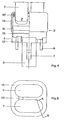
- FIGS. 4 to 7 Another exemplary embodiment is shown in FIGS. 4 to 7.
- the discharge vessel 1 ' here consists of two identical glass tubes, which are connected to one another by means of a connecting web 13 and are bent approximately in a U-shape, the four adjacent ends 2' of which, as in the previous example, are sealed by means of a pinch seal and open into a base 3 '. In this case, however, only the start and end point of the discharge path is provided with an electrode.
- the base part 4 is identical to that of Figures 1 to 3. In contrast to this, however, the base cover is here divided into a cover cap 14 and an adapter part 15.
- the base cover In order to be able to accommodate the four adjacent ends 2 'of the discharge vessel 1' in the base 3 ', the base cover must have a correspondingly enlarged cross section.
- the cover cap 14 therefore has an approximately square cross section in which the corners are rounded (FIG. 6).
- the adapter part 15 has the task of aligning these different cross sections of the lower base part 4 (FIG. 2) and the top cap 14 (FIG. 6) and therefore has a cross section which widens upwards.
- the adapter part 15 is fastened to the base part 4 by means of a snap connection (11 ', 12).
- the connection between the top cap 14 and the adapter part 15 is made at the point 16, wherein a plurality of latching lugs distributed on the inner circumference of the adapter part 15 snap into the recesses provided on the top cap 14.
- the discharge vessel 1 ' is fastened at its ends 2', similar to the exemplary embodiment of the two-leg discharge vessel 1 (FIG. 1), to the cover cap 14 by means of cement 10 '.
Abstract
Description
Die Erfindung betrifft eine kompakte Leuchtstofflampe mit einem einseitig gesockelten Entladungsgefäß, bei der der Sockel ein mit den elektrischen Anschlußelementen versehenes Sockelunterteil aus einem isolierenden Material mit einer oberen Öffnung sowie eine das Ende des Entladungsgefäßes umgebende und die Öffnung des Sockelunterteils verschließende Sockelabdeckung aufweist und Mittel zur Verbindung der Sokkelabdeckung mit dem Sockelunterteil vorgesehen sind.The invention relates to a compact fluorescent lamp with a discharge vessel with a base on one side, in which the base has a base part made of insulating material provided with the electrical connection elements and having an upper opening, as well as a base cover surrounding the end of the discharge vessel and closing the opening of the base part, and means for connecting the base cover is provided with the base part.
In einer speziellen Ausführungsform dieser Lampe weist das Entladungsgefäß zwei parallel zueinander verlaufende Schenkel auf, die im oberen Bereich miteinander verbunden sind. In einer Weiterbildung dieses Gegenstandes sind zwei solcher Entladungsgefäße im unteren Bereich durch einen von der Entladung durchströmten Steg verbunden, wobei in diesem Fall die Elektroden jeweils nur an den Endpunkten der Entladungsstrecke angeordnet sind. Die Enden jedes Schenkels münden in einen Sockel, der auch einen Starter beinhaltet.In a special embodiment of this lamp, the discharge vessel has two legs that run parallel to one another and are connected to one another in the upper region. In a further development of this object, two such discharge vessels are connected in the lower region by a web through which the discharge flows, in which case the electrodes are only arranged at the end points of the discharge path. The ends of each leg open into a base that also includes a starter.
Es ist bekannt, daß der im Spritzgußverfahren hergestellte Sockelunterteil aus Kunststoff besteht. Die obere Öffnung des Sockelunterteils nimmt die Schenkelenden des Entladungsgefäßes auf. Der verbleibende, noch freie Teil der Öffnung des Sockelunterteils ist mit einer die Schenkel umgebenden und aus Aluminium bestehenden Sockelabdeckung versehen, wobei zur Befestigung dieser beiden Teile miteinander die verformbare Sockelabdeckung am unteren Rand in entsprechende Vertiefungen des Sockelunterteils gedrückt ist. Die Befestigung des Entladungsgefäßes innerhalb des Sokkels erfolgt mittels Kitt, der durch Temperaturanwendung aushärtet.It is known that the base part produced by injection molding consists of plastic. The upper opening of the lower base part receives the leg ends of the discharge vessel. The remaining, still free part of the opening of the lower part of the base is provided with a base cover which surrounds the legs and is made of aluminum bare base cover is pressed at the bottom into corresponding recesses of the base part. The discharge vessel is fastened within the pedestal by means of putty, which hardens through application of temperature.
Die hier beschriebene Sockelkonstruktion sowie das Montageverfahren hat verschiedene Nachteile. Bei Montagefehlern können spannungsführende Teile der Stromzuführungen mit der Sockelabdeckung aus Aluminium Kontakt erhalten, wodurch ein erhebliches Sicherheitsrisiko entsteht. Auch kann es bei zu geringem Abstand zwischen den spannungsführenden Stromzuführungen und der metallischen Sockelhülse zu Überschlägen kommen. Außerdem sind zur Befestigung der Sockelteile miteinander formverändernde Arbeitsgänge mit entsprechenden Werkzeugen an der Sockelabdeckung erforderlich.The base construction described here as well as the assembly method have various disadvantages. In the event of assembly errors, live parts of the power supply lines can come into contact with the aluminum base cover, which creates a considerable safety risk. If the distance between the live power supply lines and the metal base sleeve is too small, flashovers may occur. In addition, to change the base parts shape-changing operations with appropriate tools on the base cover are required.
Aufgabe der Erfindung ist es, eine Sockelkonstruktion zu schaffen, die maschinell leicht, schnell und kostengünstig zu montieren ist und insbesondere hinsichtlich der elektrischen Sicherheit mögliche Fehlerquellen und damit auch Unfallgefahren für den Anwender ausschließt.The object of the invention is to provide a base construction which can be assembled mechanically easily, quickly and inexpensively and which, in particular with regard to electrical safety, excludes possible sources of error and thus also the risk of accidents for the user.
Die kompakte Leuchtstofflampe mit den im Oberbegriff des Hauptanspruchs genannten Merkmalen ist dadurch gekennzeichnet, daß die Sockelabdeckung ebenfalls aus einem isolierenden Material besteht und mit mehreren Rastelementen versehen ist, die mit entsprechenden Paßelementen des Sockelunterteils zusammenwirken, wodurch eine formschlüssige Verbindung zwischen der Sockelabdeckung und dem Sockelunterteil gegeben ist. In einer Weiterbildung des Gegenstandes der Erfindung ist die Sockelabdeckung in einen Adapterteil und eine Deckkappe aufgeteilt. Die Deckkappe weist hierbei einen von der zu verschließenden Öffnung des Sockelunterteils abweichenden Querschnitt auf und das Adapterteil ist zur Anpassung dieser unterschiedlichen Querschnitte vorgesehen. Ein solcher Fall liegt zum Beispiel vor, wenn an Stelle von zwei Entladungsgefäßschenkeln vier in etwa einem Quadrat angeordnete Schenkel in dem Sockel enden. Der Querschnitt der Sockelabdeckung verdoppelt sich hierbei nahezu, während das in die Fassung einzusetzende Sockelunterteil Normmaßen unterliegt und somit gleich groß bleibt. Ein anderer Fall einer erforderlichen Querschnittsvergrößerung ist z.B. gegeben, wenn in der Sockelabdeckung auch ein Vorschaltgerät untergebracht ist. Die Verbindung zwischen der Deckkappe und dem Adapterteil erfolgt zweckmäßig ebenfalls mittels an die Deckkappe angeformter Rastelemente, die mit entsprechenden Paßelementen des Adapterteils zusammenwirken. Die Rastelemente sind zweckmäßig als Rastnasen und die Paßelemente als Vertiefungen ausgebildet. Hierdurch kann das herkömmliche Sockelunterteil ohne Veränderungen verwendet werden.The compact fluorescent lamp with the features mentioned in the preamble of the main claim is characterized in that the base cover is also made of an insulating material and is provided with a plurality of latching elements which cooperate with corresponding fitting elements of the base part of the base, whereby a positive connection between the base cover and the base part is given is. In a further development of the subject of the invention, the base cover is in an adapter part and a deck split cap. The cover cap has a cross-section that deviates from the opening of the base part to be closed, and the adapter part is provided to adapt these different cross-sections. Such a case is present, for example, if instead of two discharge vessel legs, four legs arranged approximately in a square end in the base. The cross-section of the base cover almost doubles, while the base part to be inserted into the socket is subject to standard dimensions and thus remains the same size. Another case of a necessary cross-sectional enlargement is given, for example, if a ballast is also accommodated in the base cover. The connection between the cover cap and the adapter part is also expediently carried out by means of locking elements molded onto the cover cap, which interact with corresponding fitting elements of the adapter part. The locking elements are expediently designed as locking lugs and the fitting elements as depressions. As a result, the conventional base part can be used without changes.
Ein derartiger Sockel für eine kompakte Leuchtstofflampe besteht für ein zweischenkliges Entladungsgefäß aus einem Sockelunterteil und einer Sockelabdeckung, die mittels einer einfachen Rastverbindung aneinander befestigt sind. Ein Entladungsgefäß mit mehr als zwei Schenkeln erfordert eine entsprechend vergrößerte Sockelabdeckung. Hierfür ist diese in eine an die entsprechende Schenkelanzahl angepaßte Deckkappe und ein Adapterteil aufgeteilt. Der obere Teil des Adapterteils ist dem Querschnitt der Deckkappe und der untere Teil des Adapterteils dem des Sockelunterteils angepaßt. Die zu verbindenden Teile sind zur Montageerleichterung an den sich berührenden Stellen mit mehreren ineinandergreifenden Verriegelungselementen versehen. Ein weiterer Vorteil dieser Konstruktion besteht darin, daß bei unterschiedlichen Sockelabdeckungen (Deckkappe plus zugehörigem Adapterteil) jeweils das gleiche Sockelunterteil verwendet werden kann. Hierdurch ergibt sich eine universelle Einsatzmöglichkeit der Einzelteile. Auch werden auf diese Weise die Werkzeugkosten für den gesamten Sockel niedrig gehalten.Such a base for a compact fluorescent lamp for a two-leg discharge vessel consists of a base part and a base cover which are fastened to one another by means of a simple snap connection. A discharge vessel with more than two legs requires a correspondingly enlarged base cover. For this purpose, it is divided into a cover cap adapted to the corresponding number of legs and an adapter part. The upper part of the adapter part is adapted to the cross section of the top cap and the lower part of the adapter part is adapted to that of the base part. The parts to be connected are for assembly Relief provided at the touching points with several interlocking locking elements. Another advantage of this construction is that the same base part can be used with different base covers (top cap plus associated adapter part). This results in a universal application of the individual parts. The tool costs for the entire base are also kept low in this way.
Sämtliche Einzelteile sind im Spritzgußverfahren aus Kunststoff einfach und billig hergestellt. Die Verbindung dieser Einzelteile erfolgt mittels der angespritzten Rastnasen und Vertiefungen schnell, einfach und kostengünstig. Es werden keine zusätzlichen formverändernden Werkzeuge mehr benötigt, sondern die Montage der Teile kann durch Ausüben eines geringen axialen Drucks auf mechanisierten Fertigungslinien erfolgen. Die Verwendung von Kunststoff bietet einen sicheren Berührungsschutz (Schutzklasse II) und entspricht somit den Bestimmungen nach VDE und IEC.All individual parts are easily and inexpensively manufactured using plastic injection molding. These individual parts are connected quickly, easily and inexpensively by means of the molded locking lugs and recesses. No additional shape-changing tools are required, but the parts can be assembled by exerting a small axial pressure on mechanized production lines. The use of plastic offers safe protection against contact (protection class II) and thus complies with the provisions of VDE and IEC.
Die Erfindung wird nachfolgend anhand der Figuren näher erläutert:
Figur 1 zeigt den Sockelaufbau einer zweischenkligen einseitig gesockelten LeuchtstofflampeFigur 2 zeigt die Draufsicht derFigur 1 ohne das EntladungsgefäßFigur 3 zeigt die Verbindung zwischen dem Sockelunterteil und der Sockelabdeckung derFigur 1Figur 4 zeigt den Sockelaufbau einer vierschenkligen einseitig gesockelten LeuchtstofflampeFigur 5 zeigt die Seitenansicht derFigur 4Figur 6 zeigt die Draufsicht derFigur 4Figur 7 zeigt die Verbindung zwischen dem Sockelunterteil und der Sockelabdeckung derFigur 4
- Figure 1 shows the base structure of a two-leg fluorescent lamp with a base on one side
- Figure 2 shows the top view of Figure 1 without the discharge vessel
- FIG. 3 shows the connection between the base part and the base cover of FIG. 1
- FIG. 4 shows the base structure of a four-leg fluorescent lamp with a base on one side
- FIG. 5 shows the side view of FIG. 4
- FIG. 6 shows the top view of FIG. 4
- FIG. 7 shows the connection between the lower base part and the base cover of FIG. 4
Die Figuren 1 bis 3 zeigen eine kompakte Leuchtstofflampe mit einem abgeschnittenen Entladungsgefäß 1, das aus einem etwa U-förmig gebogenen Glasrohr besteht, dessen zwei benachbarte Enden 2 mittels einer Quetschung abgedichtet sind und in einem Sockel 3 enden. Der Sockel 3 weist ein Sockelunterteil 4 auf, an den ein Führungszapfen 5 angeformt ist und an dem zwei Anschlußstifte 6 befestigt sind. Der Führungszapfen 5 nimmt einen Starter (nicht dargestellt) auf und ist zur Verriegelung in einer Fassung mit Nocken 7 versehen. Des weiteren enthält der Sockel eine Sockelabdeckung 8 mit zwei Öffnungen 9, durch die die beiden Enden 2 des Entladungsgefäßes 1 in das Innere des Sockels 3 geführt sind. Das Entladungsgefäß 1 ist an seinen Enden 2 mittels Kitt 10 an der Sockelabdeckung 8 befestigt. Die Sockelabdeckung 8 ist mit dem Sockelunterteil 4 mittels einer Schnappverbindung fest verbunden. Hierfür weist die Sockelabdeckung 8 mehrere am inneren Umfang verteilte Rastnasen 11 auf, die in entsprechende, am herkömmlichen Sockelunterteil 4 bereits vorhandene Vertiefungen 12 einrasten. In die Vertiefungen 12 wird bei herkömmlichen Sockeln dieser Art die aus Aluminium bestehende obere Sockelabdeckung eingedrückt.Figures 1 to 3 show a compact fluorescent lamp with a cut-off
Ein weiteres Ausführungsbeispiel ist in den Figuren 4 bis 7 dargestellt. Das Entladungsgefäß 1' besteht hierbei aus zwei gleichartigen, miteinander mittels eines Verbindungssteges 13 verbundenen, etwa U-förmig gebogenen Glasrohren, deren vier benachbarte Enden 2' wie im vorangegangenen Beispiel mittels einer Quetschung abgedichtet sind und in einem Sockel 3' münden. In diesem Fall ist jedoch nur der Anfangs- und Endpunkt der Entladungsstrecke mit einer Elektrode versehen. Das Sockelunterteil 4 ist mit dem aus den Figuren 1 bis 3 identisch. Im Gegensatz dazu ist die Sockelabdeckung hier jedoch in eine Deckkappe 14 und ein Adapterteil 15 aufgeteilt. Um die vier benachbarten Enden 2' des Entladungsgefäßes 1' im Sockel 3' unterbringen zu können, muß die Sockelabdeckung einen entsprechend vergrößerten Querschnitt aufweisen. Die Deckkappe 14 weist deshalb einen etwa quadratischen Querschnitt auf, bei dem die Ecken abgerundet sind (Figur 6). Das Adapterteil 15 hat die Aufgabe, diese unterschiedlichen Querschnitte des Sockelunterteils 4 (Figur 2) und der Deckkappe 14 (Figur 6) aneinander anzugleichen und weist deshalb einen sich nach oben erweiternden Querschnitt auf. Das Adapterteil 15 ist wie im vorherigen Ausführungsbeispiel mittels einer Schnappverbindung (11', 12) an dem Sockelunterteil 4 befestigt. Auf die gleiche Weise ist auch die Verbindung zwischen der Deckkappe 14 und dem Adapterteil 15 an der Stelle 16 vorgenommen, wobei mehrere am inneren Umfang des Adapterteiles 15 verteilte Rastnasen in die an der Deckkappe 14 vorhandenen Vertiefungen einrasten. Das Entladungsgefäß 1' ist an seinen Enden 2', ähnlich wie im Ausführungsbeispiel des zweischenkligen Entladungsgefäßes 1 (Figur 1), mittels Kitt 10' an der Deckkappe 14 befestigt.Another exemplary embodiment is shown in FIGS. 4 to 7. The
Claims (4)
Applications Claiming Priority (2)
| Application Number | Priority Date | Filing Date | Title |
|---|---|---|---|
| DE3410827 | 1984-03-23 | ||
| DE19843410827 DE3410827A1 (en) | 1984-03-23 | 1984-03-23 | COMPACT FLUORESCENT LAMP |
Publications (3)
| Publication Number | Publication Date |
|---|---|
| EP0156291A2 true EP0156291A2 (en) | 1985-10-02 |
| EP0156291A3 EP0156291A3 (en) | 1986-12-03 |
| EP0156291B1 EP0156291B1 (en) | 1988-08-10 |
Family
ID=6231471
Family Applications (1)
| Application Number | Title | Priority Date | Filing Date |
|---|---|---|---|
| EP85103175A Expired EP0156291B1 (en) | 1984-03-23 | 1985-03-19 | Compact fluorescent lamp |
Country Status (3)
| Country | Link |
|---|---|
| EP (1) | EP0156291B1 (en) |
| JP (1) | JPS60212939A (en) |
| DE (2) | DE3410827A1 (en) |
Families Citing this family (6)
| Publication number | Priority date | Publication date | Assignee | Title |
|---|---|---|---|---|
| JPS62133353U (en) * | 1986-02-18 | 1987-08-22 | ||
| DE4129219C2 (en) * | 1991-09-03 | 1994-03-10 | Wismeth Wolfgang | Lamp housing for a compact fluorescent tube |
| HU213598B (en) * | 1994-10-18 | 1997-08-28 | Ge Lighting Tungsram Rt | One-side socketed discharge lamp |
| DE19817407A1 (en) * | 1998-04-20 | 1999-10-21 | Walter Holzer | Bayonet socket for gas discharge lamps |
| DE202004012293U1 (en) * | 2004-08-05 | 2005-12-15 | Patent-Treuhand-Gesellschaft für elektrische Glühlampen mbH | Single ended lamp |
| JP4860443B2 (en) * | 2006-11-20 | 2012-01-25 | パナソニック株式会社 | Fluorescent lamp |
Citations (3)
| Publication number | Priority date | Publication date | Assignee | Title |
|---|---|---|---|---|
| FR838557A (en) * | 1937-05-31 | 1939-03-09 | Philips Nv | Electric discharge tube |
| GB607471A (en) * | 1945-02-12 | 1948-08-31 | British Thomson Houston Co Ltd | Improvements in and relating to bases for electric lamps |
| GB2077488A (en) * | 1980-06-04 | 1981-12-16 | Philips Nv | Low presure mercury vapour discharge lamp |
-
1984
- 1984-03-23 DE DE19843410827 patent/DE3410827A1/en not_active Withdrawn
-
1985
- 1985-03-19 DE DE8585103175T patent/DE3564357D1/en not_active Expired
- 1985-03-19 EP EP85103175A patent/EP0156291B1/en not_active Expired
- 1985-03-22 JP JP60055724A patent/JPS60212939A/en active Pending
Patent Citations (3)
| Publication number | Priority date | Publication date | Assignee | Title |
|---|---|---|---|---|
| FR838557A (en) * | 1937-05-31 | 1939-03-09 | Philips Nv | Electric discharge tube |
| GB607471A (en) * | 1945-02-12 | 1948-08-31 | British Thomson Houston Co Ltd | Improvements in and relating to bases for electric lamps |
| GB2077488A (en) * | 1980-06-04 | 1981-12-16 | Philips Nv | Low presure mercury vapour discharge lamp |
Also Published As
| Publication number | Publication date |
|---|---|
| EP0156291B1 (en) | 1988-08-10 |
| DE3564357D1 (en) | 1988-09-15 |
| JPS60212939A (en) | 1985-10-25 |
| EP0156291A3 (en) | 1986-12-03 |
| DE3410827A1 (en) | 1985-09-26 |
Similar Documents
| Publication | Publication Date | Title |
|---|---|---|
| DE10012387C2 (en) | Arrangement for connecting a cable to a motor vehicle battery pole | |
| DE3210005A1 (en) | COMPACT FLUORESCENT LAMP | |
| DE3405533A1 (en) | PLUG WITH FUSE | |
| EP0492086A1 (en) | Double flat spring contact with a stop | |
| EP0621656B1 (en) | Electrical terminal device | |
| DE2933359A1 (en) | ELECTRIC LAMP WITH A SOCKET-BASED BASE | |
| DE19857802A1 (en) | Compact fluorescent lamp with electrical connections between leads | |
| EP0156291B1 (en) | Compact fluorescent lamp | |
| DE4431274C2 (en) | Method of manufacturing an electrical installation device and electrical installation device | |
| DE19607714A1 (en) | transformer | |
| DE2941011C2 (en) | ||
| DE3906625C1 (en) | Electrical plug contact part | |
| DE19701195A1 (en) | Compact low pressure discharge lamp | |
| EP0854496A2 (en) | Compact low pressure discharge lamp | |
| EP0378065B1 (en) | Part of a case with a plug mounted thereon | |
| DE3221111C2 (en) | Explosion-proof or firedamp-proof electrical coupling connector | |
| DE2004840C3 (en) | Base and socket for electron tubes | |
| DE2928479A1 (en) | HOUSING FOR ELECTRICAL COMPONENTS | |
| DE2304510A1 (en) | SMALL GLASS LAMP WITH LATERAL CONTACT LAMPS | |
| DE3531072C2 (en) | ||
| DE3644140A1 (en) | EXPLOSION OR FLASH-PROTECTED LAMP | |
| DE19854440A1 (en) | Extension piece for short fluorescent lamp has internal contact elements coupling fluorescent lamp contact pins received by one end of extension piece to corresponding contact pins projecting from opposite end of extension piece | |
| EP0304906A2 (en) | Connection piece for an electric cooking plate | |
| DE3629779C1 (en) | Electrical series terminal arrangement | |
| DE3908618C2 (en) |
Legal Events
| Date | Code | Title | Description |
|---|---|---|---|
| PUAI | Public reference made under article 153(3) epc to a published international application that has entered the european phase |
Free format text: ORIGINAL CODE: 0009012 |
|
| AK | Designated contracting states |
Designated state(s): DE FR GB IT SE |
|
| PUAL | Search report despatched |
Free format text: ORIGINAL CODE: 0009013 |
|
| AK | Designated contracting states |
Kind code of ref document: A3 Designated state(s): DE FR GB IT SE |
|
| 17P | Request for examination filed |
Effective date: 19861023 |
|
| 17Q | First examination report despatched |
Effective date: 19871214 |
|
| GRAA | (expected) grant |
Free format text: ORIGINAL CODE: 0009210 |
|
| AK | Designated contracting states |
Kind code of ref document: B1 Designated state(s): DE FR GB IT SE |
|
| REF | Corresponds to: |
Ref document number: 3564357 Country of ref document: DE Date of ref document: 19880915 |
|
| GBT | Gb: translation of ep patent filed (gb section 77(6)(a)/1977) | ||
| ET | Fr: translation filed | ||
| ITF | It: translation for a ep patent filed |
Owner name: STUDIO JAUMANN |
|
| PG25 | Lapsed in a contracting state [announced via postgrant information from national office to epo] |
Ref country code: GB Effective date: 19890319 |
|
| PG25 | Lapsed in a contracting state [announced via postgrant information from national office to epo] |
Ref country code: SE Effective date: 19890320 |
|
| PLBE | No opposition filed within time limit |
Free format text: ORIGINAL CODE: 0009261 |
|
| STAA | Information on the status of an ep patent application or granted ep patent |
Free format text: STATUS: NO OPPOSITION FILED WITHIN TIME LIMIT |
|
| 26N | No opposition filed | ||
| GBPC | Gb: european patent ceased through non-payment of renewal fee | ||
| PG25 | Lapsed in a contracting state [announced via postgrant information from national office to epo] |
Ref country code: FR Free format text: LAPSE BECAUSE OF NON-PAYMENT OF DUE FEES Effective date: 19891130 |
|
| PG25 | Lapsed in a contracting state [announced via postgrant information from national office to epo] |
Ref country code: DE Effective date: 19891201 |
|
| REG | Reference to a national code |
Ref country code: FR Ref legal event code: ST |
|
| EUG | Se: european patent has lapsed |
Ref document number: 85103175.7 Effective date: 19891016 |