EP0162933A1 - Procédé et installation pour déposer de façon déterminée des articles, en particulier des pralines, dans des récipients d'emballage - Google Patents
Procédé et installation pour déposer de façon déterminée des articles, en particulier des pralines, dans des récipients d'emballage Download PDFInfo
- Publication number
- EP0162933A1 EP0162933A1 EP84104796A EP84104796A EP0162933A1 EP 0162933 A1 EP0162933 A1 EP 0162933A1 EP 84104796 A EP84104796 A EP 84104796A EP 84104796 A EP84104796 A EP 84104796A EP 0162933 A1 EP0162933 A1 EP 0162933A1
- Authority
- EP
- European Patent Office
- Prior art keywords
- movement
- coordinate
- transport
- storage location
- receptacles
- Prior art date
- Legal status (The legal status is an assumption and is not a legal conclusion. Google has not performed a legal analysis and makes no representation as to the accuracy of the status listed.)
- Granted
Links
Images


Classifications
-
- B—PERFORMING OPERATIONS; TRANSPORTING
- B65—CONVEYING; PACKING; STORING; HANDLING THIN OR FILAMENTARY MATERIAL
- B65B—MACHINES, APPARATUS OR DEVICES FOR, OR METHODS OF, PACKAGING ARTICLES OR MATERIALS; UNPACKING
- B65B5/00—Packaging individual articles in containers or receptacles, e.g. bags, sacks, boxes, cartons, cans, jars
- B65B5/10—Filling containers or receptacles progressively or in stages by introducing successive articles, or layers of articles
- B65B5/12—Introducing successive articles, e.g. confectionery products, of different shape or size in predetermined positions
Definitions
- the invention relates to a method for the orderly insertion of objects, in particular chocolates, into receptacles, for example packaging inserts for sales boxes, in which the receptacles, each of which within a loading area, each have a number by means of an X and a Y coordinate in a co-ordinate coordinate system is assigned to certain storage locations, are transported at fixed mutual intervals in succession in a predetermined direction (X direction) past at least one insertion station and in the insertion station the individually picked up objects in a cyclical insertion movement synchronized with the transport movement of the receiving containers transversely to the X direction ( in the Y direction) in accordance with the Y coordinate of the controlled storage location is moved over a receiving container and is inserted at the storage location into the receiving container transported past.
- the invention also relates to a device for carrying out this method, with a continuously driven transport device which transports the holding containers, which are held at fixed mutual distances, in a predetermined direction (X-direction) and at least one loading device arranged in an insertion station next to the transport device, the one the article-feeding device is assigned and the one receiving the article and in a cyclical insertion movement along a predetermined path via one of the receptacles transported by the transport device past the insertion device to a position corresponding to the Y-coordinate of the respectively controlled storage location and transferring it at the location Inserting means are assigned to the storage location, the drive of the insertion device being synchronized with the drive of the transport device.
- a device operating according to the above-mentioned method with these features is known from US-A-3191 357. It is used to place confectionery pieces or chocolates, preferably in paper cups, in sales boxes, the interior of which is divided into rows and columns of rectangular cross-sectional compartments by a packaging insert with walls crossing at right angles.
- the sales boxes are one by one at fixed intervals arranged carrier carrying, continuously driven conveyor through an insertion station, in which a plurality of insertion devices are arranged side by side on both sides of the conveyor.
- Each of these inserting devices has an elongated closed path which lies in a horizontal plane parallel to the conveyor and along which the individually fed chocolates are moved by inserting means which are designed in the form of a resilient inserting judge and an associated inserting plunger.
- the closed path is laid with a straight path part above the conveyor parallel to its transport direction in such a way that the chocolates moved along this path part in the same direction as the conveyor are each exactly above their respective storage location when the insertion ram becomes effective.
- Another device for inserting chocolates or the like in packaging inserts allows confectionery pieces, in particular chocolates, to be placed anywhere on a packaging insert without the position of the entire device relative to the associated conveyor for the Packaging inserts would have to be changed.
- relatively time-consuming conversion work is also required here.
- the chocolates are in each case aligned in rows by means of parallel conveyor tracks in the Y direction via the packaging inserts transported in the X direction against adjustable stops, the setting of which corresponds to the Y coordinate of the respective storage location.
- Individual objects are removed from the parallel rows thus pent-up by assigned grippers, which can be moved in parallel paths extending in the X direction, and inserted at the respective storage location of the respective packaging insert.
- the object of the invention is therefore to provide a method and a device which allow objects, in particular chocolates, to be automatically inserted at freely selectable storage locations in the passing receptacles, for example packaging inserts, and the storage location can be freely programmed, for example by Change receptacle to receptacle.
- the method mentioned in the introduction proceeds according to the invention in such a way that the insertion movement is phase-shifted in time with respect to the transport movement by a fixed value which is dependent on the X coordinate of a storage location which is optionally controlled.
- the insertion movement can take place along a path that is perpendicular to the X direction and lies in a vertical plane, which results in the smallest lateral space requirement in the X direction results. A plurality of such insertion movements can therefore be carried out side by side in a narrow space.
- the insertion movement takes place over a constant path in the Y direction, the stroke path being shifted in the Y direction depending on the Y coordinate of the controlled storage location.
- the objects are given an additional movement component in the X direction, at least in the last movement phase preceding the storage.
- the new method allows a freely programmable, optional control of any storage location in the continuously moving receptacles, without having to interrupt the operation.
- a device for performing the method with the features mentioned at the outset is characterized according to the invention in that it has a device for generating a phase shift corresponding to the X coordinate of an optionally controlled storage location between the drives of the insertion device and the transport device.
- the drives of the insertion and transport device can be coupled to one another via a twist clutch, which in a preferred embodiment is formed by a differential gear, into which an additional rotary movement can be initiated by an assigned actuator.
- a simple control intervention on the actuator can thus be used to selectively control any storage location in the X-direction at a different location from work cycle to work cycle of the receiving containers passing the insertion device.
- the control intervention on the actuator does not require stopping the system, so that it is readily possible to produce different levels and to feed pack for example.
- the working movement of the inserting means and the transport device is independent of the adjustment movement which the actuator carries out.
- the insertion device has an insertion head which carries the movable insertion means, which is adjustably mounted on stationary guideways in the Y direction and is coupled to an actuator which effects the adjustment according to the Y coordinate of the optionally controlled storage location.
- an actuator which effects the adjustment according to the Y coordinate of the optionally controlled storage location.
- the insertion means which are designed as grippers or suction devices, can be movably mounted on the insertion head by means of a cam-controlled lever transmission along a predetermined path, which lies in a vertical plane extending in the Y direction.
- a particularly narrow design of the entire insertion device which can be designed, for example, in the form of a narrow unit, the width of which is smaller than the length of a receptacle, in which case a number of these narrow units can be arranged next to one another on both sides of the transport device in the insertion station , so that a minimal longitudinal extension of the insertion station is achieved.
- the feed device for the objects is coupled to the inserting head in such a way that it can be adjusted together with the inserting head so that the Insert means can always pick up the supplied objects at the same distance.
- the feed device can row the objects to one of the movement paths of the inserting means have spatially firmly assigned receiving point bringing conveyor.
- the transport device which moves the receptacles, arranged one behind the other at fixed intervals, through the insertion station, can be designed in the form of a belt or chain conveyor which carries drivers for the receptacles arranged at fixed intervals.
- the arrangement can also be such that the transport device has an optionally continuously driven smooth conveyor track, on which the receptacles lie one behind the other and to which, in the area of the insertion station, at least on one side is associated a continuous, endless conveying means which is arranged at equal intervals, carries on the receptacles engaging from the side and is partially guided parallel to the conveyor track with a strand, its drive being synchronized with the drive of the insertion device and the conveyor being driven at a relative speed to the conveyor track.
- the receptacles are pressed against the drivers during the movement through the insertion station with a frictional force resulting from the relative movement to the conveyor track. This ensures that the receptacle is at exactly the same intervals and therefore at exactly the same Work cycles run through the insertion station and are perfectly aligned at the same time.
- the distance between the carriers corresponds to the maximum value of the length of the transported receptacles; Regardless of their length, the receptacles always lie snugly on one side on the drivers, so that the storage locations are also controlled with the correct coordinates.
- the drivers are advantageously arranged at the level of the side walls of the shaped recesses for receiving the chocolates.
- the packaging inserts that are deep-drawn from plastic film material are often only dimensionally accurate in the areas of the depressions produced in the deep-drawing molds. If the drivers attack the side walls of the recesses, the packaging inserts are always conveyed in the correct position.
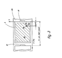
- an insertion station in which objects in the form of confectionery pieces or chocolates 1 are placed in an orderly manner in packaging inserts for sales boxes indicated at 2 in their outlines.
- the general receptacles for the packaging inserts 2 forming chocolates are transported in a row one behind the other by a transport device 3 in the X direction indicated by an arrow 40 and are moved through the insertion station.
- In the loading station there are eight loading devices 4 on the side next to the Transport device 3 arranged, which are assigned individually or in pairs at 5 indicated feed devices for the chocolates 1.
- the insertion devices 4 are designed as narrow units, the width of which is smaller than the length of a packaging insert 2.
- Each insertion device 4 inserts a certain type of chocolates 1 into the packaging inserts 2, which are successively guided through the insertion station 3 by the transport device 3 at a respectively selected storage location .
- Each feed device 5 has a conveyor belt 6 rotating in the direction of the arrow, onto which chocolates 1 are placed in an unordered manner at 7, which are transported by the conveyor belt 6 against stop bars 8 projecting obliquely into its path of movement, to which they are aligned in a manner known per se when sliding along will.
- the chocolates 1 run from the conveyor belt 6, guided by a deflection piece 9, aligned in the correct orientation, into a feed channel 10, to which a switch 11 connects, which, if necessary, the isolated chocolates 1 via a feed channel 12a or 12b one of the two of the Feeder 5 allocated insertion devices 4.
- each insertion device 4 is alternatively assigned its own feed device 5.
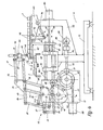
- the lever mechanism 20 has a lever 24 which is pivotably mounted in the housing 17 at 38, which is driven via a cam roller 230 which engages in a curved path 42a of the cam disk 18 and at the other end articulated via a tab 25 with a second, at 23 on the housing 17th pivotally mounted lever 27 is connected.
- a third lever 29, which forms part of the insertion arm 21 is connected in an articulated manner via a coupling member 28, which at the other end is articulated via a connecting member 31 with a parallel guide lever 32, which in turn is articulated on a connecting piece 33 which on the third lever 29 at. 34 and is mounted on parallel coupling links 35.
- a lever 350 is welded outward at right angles, which over a at the end hingedly connected tab 36 is coupled to a lever 37.
- the lever 37 is mounted on the articulation point 38 and rigidly connected to a drive lever 39 which carries at its free end a roller 400 which engages in a curved path 42 of the cam plate 18.
- the cam tracks 42, 42a are arranged on the opposite sides of the cam disk 18.
- a bearing part 43 is fastened on the front side, on which a holder 44 is mounted such that it can be pivoted to a limited extent about a horizontal axis indicated at 45, in which the suction device or gripper 22 is held.
- the lever mechanism 20 is constructed in such a way that, when the cam disk 18 rotates, the head of the suction or gripper 22 indicated at 46 passes through a movement path, indicated by dashed lines at 47, in a vertical plane, in which it executes a cyclical insertion movement.
- the head 46 is first raised, then, relative to FIG. 4, moved to the left and lowered at the same time, whereupon it is raised again after a short dwell time and returned to the position according to FIG. 4.
- the cam 18 is driven via a differential gear 50 arranged in the housing 17 from a drive shaft 52, which is also rotatably mounted on the housing 17 and which has splines, via which it is coupled in a rotationally fixed and longitudinally displaceable manner to a hollow shaft 54 which is rotatably mounted on a carrier 53 of the base frame 13.
- the hollow shaft 54 is in turn rigidly coupled to the drive source of the transport device 3 (FIG. 1, 2) via a bevel gear 55 and a shaft 56.
- the drive of the cam plate 18 and thus the insertion device 4 is thus synchronized with the drive of the transport device 3, ie the driver 81.
- the differential gear 50 is coupled via a shaft 57 to a servomotor 58 attached to the housing 17, which allows an additional rotary movement to be introduced into the differential gear 50, by means of which the spline shaft differential gear is rotated, so that the cam disk 18 and the drive shaft 52 in their angular position can be rotated against each other by a predetermined value.
- the differential gear 50 could also be replaced by a differently designed torsion clutch, which permits this adjustment of the mutual angular position between the cam 18 and the drive shaft 56.
- a second servomotor 60 is flanged, which drives a threaded spindle 61, which via a in A spindle nut 62 inserted at the end of the end plate 63 connected to the guide rods 15 allows the insertion head 16 to be moved back and forth linearly in the direction of the guide formed by the guide rods 15, as is indicated by the double arrow 64.
- a table 65 is arranged on the carrier 53, on which an endless feed conveyor belt 66 is guided, which extends over a subsequent table part 67 of the L-shaped end plate 63, on which it is guided at 68 at the end via a deflection roller.
- the feed conveyor belt 66 is part of a feed conveyor 70 adjoining the feed channel 12a or 12b of FIG. 1, from which the individual chocolates 1 are successively brought up and pent up against a stop 71 arranged at the end of the table part 67.
- the feed conveyor belt 66 is guided in a loop 72 over a length compensation device which has a spring-loaded compensation oscillation 74 which is supported on the end 53 by a deflection roller 73 and is pivotably mounted on the carrier 53 has, which are assigned two frame-fixed deflection rollers 75.
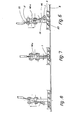
- the transport device 3 has an endless rotating at a constant speed Conveyor 80 in the form of a conveyor belt or a conveyor chain, which in the embodiment according to FIG. 2 carries carriers 81 arranged at fixed, equal intervals.
- the conveyor 80 merely forms a flat conveyor track, on the two sides of which two endless transport belts 82 which are deflected about vertical axes are arranged in the region of the insertion station, which are aligned with a strand parallel to the conveyor 80 and which extend laterally over the conveyor belt Carrier 81 projecting from conveyor 80 and again arranged at equal intervals.
- a conveyor belt 82 as seen in the transport direction 40, is laterally supported in front of the loading station at 83 via adjustable support rollers at a distance given by the width of the packaging inserts 2, while its end deflection rollers 84 are perpendicular to the transport device 40 together with the support rollers via an actuator 85 83 and the deflection rollers 84a are adjustable so that the conveyor belts 82 can be automatically adapted to packaging inserts 2 of different widths.
- the conveyor 80 runs somewhat slower than the conveyor belt 82 which is necessarily coupled with its drive source via the shaft 56 (FIG. 4) with the drive of the insertion devices 4. Because of the frictional forces acting on the bottom of the packaging inserts 2, it is thus ensured that the packaging inserts 2 rest exactly on the drivers 81 with their rear side.
- the drivers 81 are arranged on the conveyor belts 82 in such a way that they engage on the side walls of the recesses of the packaging inserts indicated at 87, i.e. in places where the thermoforming mold used in the manufacture ensures a high dimensional accuracy of the packaging inserts 2.
- the narrow insertion devices 4 each of which, for example, is only 120 mm wide, are arranged side by side in such a way that the conveyor 80 runs through them laterally next to the insertion head 16 (see also FIG. 4). .
- the insertion head 16 - and thus the associated stop 71 of the feed conveyor belt 66 - is set in the Y direction in accordance with the Y coordinate of the respectively controlled storage point 90.
- the insertion head 16 of each of the insertion devices 4, designated a to h, of the insertion station according to FIG. 2 thus conveys the generally different pralines 1 fed to it from the feed conveyor belt 66 on the movement path indicated at 47 in FIG. 4 to the storage location 90 whose Y coordinate is set. This is shown in FIG. 2 by the fact that in the packaging insert illustrated on the right, the depressions 67 are denoted by a to h.
- the cam disks 18 of the insertion devices 4 which are inevitably coupled to the drive of the transport device 3 via the shaft 56, make one revolution each time the conveyor 80 moves in FIG. 2 by a driver pitch T (FIG. 3).
- T driver pitch
- Each sucker or gripper 22 is thus lowered during one revolution of the associated control disk 18, starting from the position according to FIG. 4, onto the chocolate candy 1 standing at the associated stop 71, then raised together with the chocolate candy, over the stop 71 along the Web 47 is introduced and released in a vertical plane running in the Y direction into the recess 87 of the controlled storage location 90, which is now brought in the correct position by the synchronized conveyor 80, whereupon the sucker or gripper 22 is returned to the starting position according to FIG. 4.
- the chocolates are thus placed in the continuously passing packaging inserts 2, which are not subjected to any acceleration or deceleration forces.
- the insertion devices 4 and the transport device 3 therefore work at high working speed, the cam control given by the cam disks 18 always giving the insert arms 21 and the suction cups or grippers 22 the same insert or deposit movement.
- Such a cam control is robust, less susceptible to faults and wear-resistant, and can be optimized kinematically, which is reflected in a high working speed.
- the insertion devices 4 always insert at the same storage locations 90 to which they are set, i.e. with the same chocolate level, no notorious adjustment steps or similar wear-related measures are required.
- the newly controlled storage location 90 also requires a change in the Y coordinate, this can be achieved by a simple control intervention on the servomotor 60 and the corresponding displacement of the entire insertion head 16 in the Y direction.
- Both the phase shift described for setting the X coordinate and the control of the Y coordinate of a changed new storage location 90 can be carried out freely programmably and newly selected for each work cycle given by the passing of a packaging insert 2 or the associated drivers 81 on the insertion device 4 will.
- the necessary control commands for the actuators 58, 60 can be supplied by a programmer or a computer.
- the sucker or gripper 22 guides them each insertion device 4 when setting down a pivoting movement synchronously with the transport direction 40, for which purpose it is pivotally mounted about the axis 45.
- the suction device or gripper 22 is given an additional movement component, at least in the phase of the insertion movement preceding and following the placement of the chocolate candy 1, as is readily understandable with reference to FIGS. 6-8.
- the pivoting of the suction device or gripper 22 about the axis 45 can be motor or cam-controlled.
- the X and Y directions are perpendicular to each other. Embodiments are also conceivable in which these two directions enclose an angle deviating from 90 °.
Landscapes
- Engineering & Computer Science (AREA)
- Mechanical Engineering (AREA)
- Container Filling Or Packaging Operations (AREA)
Priority Applications (4)
| Application Number | Priority Date | Filing Date | Title |
|---|---|---|---|
| DE8484104796T DE3469875D1 (en) | 1984-04-28 | 1984-04-28 | Method and apparatus for the orderly introduction of articles, particularly pralines, into packaging containers |
| EP84104796A EP0162933B1 (fr) | 1984-04-28 | 1984-04-28 | Procédé et installation pour déposer de façon déterminée des articles, en particulier des pralines, dans des récipients d'emballage |
| AT84104796T ATE33007T1 (de) | 1984-04-28 | 1984-04-28 | Verfahren und vorrichtung zum geordneten einlegen von gegenstaenden, insbesondere pralinen, in aufnahmebehaelter. |
| US06/718,862 US4630428A (en) | 1984-04-28 | 1985-04-02 | Method and apparatus for placement of small articles, such as candies or chocolates in predetermined positions in a receiver |
Applications Claiming Priority (1)
| Application Number | Priority Date | Filing Date | Title |
|---|---|---|---|
| EP84104796A EP0162933B1 (fr) | 1984-04-28 | 1984-04-28 | Procédé et installation pour déposer de façon déterminée des articles, en particulier des pralines, dans des récipients d'emballage |
Publications (2)
| Publication Number | Publication Date |
|---|---|
| EP0162933A1 true EP0162933A1 (fr) | 1985-12-04 |
| EP0162933B1 EP0162933B1 (fr) | 1988-03-16 |
Family
ID=8191906
Family Applications (1)
| Application Number | Title | Priority Date | Filing Date |
|---|---|---|---|
| EP84104796A Expired EP0162933B1 (fr) | 1984-04-28 | 1984-04-28 | Procédé et installation pour déposer de façon déterminée des articles, en particulier des pralines, dans des récipients d'emballage |
Country Status (4)
| Country | Link |
|---|---|
| US (1) | US4630428A (fr) |
| EP (1) | EP0162933B1 (fr) |
| AT (1) | ATE33007T1 (fr) |
| DE (1) | DE3469875D1 (fr) |
Cited By (6)
| Publication number | Priority date | Publication date | Assignee | Title |
|---|---|---|---|---|
| FR2754239A1 (fr) * | 1996-10-08 | 1998-04-10 | Euresko | Dispositif alimentaire pour chaine de conditionnement d'assortiment d'articles et chaine mettant en oeuvre un tel dispositif |
| EP0856465A1 (fr) * | 1997-01-30 | 1998-08-05 | Gerhard Schubert GmbH | Transport de plateaux à directions opposées pour table de préhension |
| US6122895A (en) * | 1997-01-30 | 2000-09-26 | Gerhard Schubert Gmbh | Process and apparatus for introducing products into containers |
| EP2030894A1 (fr) * | 2007-08-27 | 2009-03-04 | MARCHESINI GROUP S.p.A. | Procédé et appareil pour remplir des cellules d'une bande alvéolée avec des articles. |
| WO2009153080A1 (fr) | 2008-06-20 | 2009-12-23 | Krones Ag | Dispositif et procédé pour le regroupement de lots pour une machine d'emballage |
| EP2778079A1 (fr) * | 2013-03-14 | 2014-09-17 | Multivac Sepp Haggenmüller GmbH & Co. KG | Machine d'emballage par emboutissage dotée d'une arrivée de produits intégrée |
Families Citing this family (14)
| Publication number | Priority date | Publication date | Assignee | Title |
|---|---|---|---|---|
| US4934126A (en) * | 1985-10-04 | 1990-06-19 | Emerson Electric Co. | Method of transporting and packaging unassembled components |
| DE3705913A1 (de) * | 1986-03-20 | 1987-11-05 | Thueringer Schokoladenwerke | Vorrichtung zum handhaben von kegelfoermigen suesswarenstuecken |
| US4785611A (en) * | 1986-12-04 | 1988-11-22 | Ralph Hasenbalg | Carton Packaging |
| JPS63196419A (ja) * | 1987-02-06 | 1988-08-15 | Fuji Photo Film Co Ltd | 平面状部材の整列方法および装置 |
| US4881356A (en) * | 1988-01-25 | 1989-11-21 | Stelron Components | Apparatus for assembling multi-part article |
| JP2966082B2 (ja) * | 1990-11-06 | 1999-10-25 | 株式会社日立製作所 | 実装順序決定方法及びその実装方法 |
| US5237801A (en) * | 1991-09-26 | 1993-08-24 | Technistar Corporation | Automated utensil packaging system |
| US5655354A (en) * | 1995-03-27 | 1997-08-12 | Tycom Corporation | Method and apparatus for automated verification and loading of precision drill bits into a drilling machine package |
| ATE224646T1 (de) * | 1997-03-25 | 2002-10-15 | Nestle Sa | Gefüllte schale auf basis von getreide |
| US5996308A (en) * | 1997-05-30 | 1999-12-07 | Shibuya Kogyo Co., Ltd. | Article processing apparatus |
| US6276115B1 (en) * | 1998-01-30 | 2001-08-21 | Lee Kramer | Method of cutting and packaging formed loin cuts |
| GB0031308D0 (en) * | 2000-12-21 | 2001-01-31 | Nestle Sa | Shell-moulded fat-containing confectionery products with viscous filling |
| NL1022955C2 (nl) * | 2003-03-17 | 2004-10-01 | Blueprint Automation B V | Samenstel en werkwijze voor het verzamelen van verschillende goederen. |
| US9371147B2 (en) * | 2012-02-14 | 2016-06-21 | Storopack Hans Reichenecker Gmbh | Method and arrangement for packing at least one article in a container and plurality of types of containers for shipping articles |
Citations (2)
| Publication number | Priority date | Publication date | Assignee | Title |
|---|---|---|---|---|
| DE1255025B (de) * | 1964-06-25 | 1967-11-23 | Hesser Ag Maschf | Maschine zum vollautomatischen Einlegen von Gegenstaenden, z. B. Pralinen, in Verpackungsbehaelter |
| FR2047100A5 (fr) * | 1969-05-05 | 1971-03-12 | Kaman Corp |
Family Cites Families (8)
| Publication number | Priority date | Publication date | Assignee | Title |
|---|---|---|---|---|
| US3191357A (en) * | 1960-06-24 | 1965-06-29 | Ael Food Machinery Division In | Apparatus for packaging confections |
| US3225513A (en) * | 1961-11-01 | 1965-12-28 | Multicup Automation Company In | Automatic packaging machine |
| US3456424A (en) * | 1966-11-18 | 1969-07-22 | Kaman Aircraft Corp | Article packaging or handling apparatus |
| CH527732A (de) * | 1969-11-08 | 1972-09-15 | Haensel Otto Gmbh | Vorrichtung zum Einlegen von Süsswarenteilen, insbes. von Pralinen, in Verpackungseinsätze |
| US3981394A (en) * | 1975-06-03 | 1976-09-21 | International Telephone And Telegraph Corporation | Feeding and assembly apparatus |
| US4043442A (en) * | 1975-08-18 | 1977-08-23 | R. A. Jones & Co. Inc. | Transfer mechanism |
| US4055943A (en) * | 1976-06-09 | 1977-11-01 | Abc Packaging Machine Corporation | Bottle loading machine |
| DE2748138C2 (de) * | 1977-10-27 | 1983-04-21 | Sapal S.A. des Plieuses Automatiques, 1024 Ecublens, Vaud | Verfahren und Vorrichtung zum Einfüllen von Pralinenmischungen in eine Schachtel |
-
1984
- 1984-04-28 EP EP84104796A patent/EP0162933B1/fr not_active Expired
- 1984-04-28 AT AT84104796T patent/ATE33007T1/de not_active IP Right Cessation
- 1984-04-28 DE DE8484104796T patent/DE3469875D1/de not_active Expired
-
1985
- 1985-04-02 US US06/718,862 patent/US4630428A/en not_active Expired - Fee Related
Patent Citations (2)
| Publication number | Priority date | Publication date | Assignee | Title |
|---|---|---|---|---|
| DE1255025B (de) * | 1964-06-25 | 1967-11-23 | Hesser Ag Maschf | Maschine zum vollautomatischen Einlegen von Gegenstaenden, z. B. Pralinen, in Verpackungsbehaelter |
| FR2047100A5 (fr) * | 1969-05-05 | 1971-03-12 | Kaman Corp |
Cited By (10)
| Publication number | Priority date | Publication date | Assignee | Title |
|---|---|---|---|---|
| FR2754239A1 (fr) * | 1996-10-08 | 1998-04-10 | Euresko | Dispositif alimentaire pour chaine de conditionnement d'assortiment d'articles et chaine mettant en oeuvre un tel dispositif |
| EP0856465A1 (fr) * | 1997-01-30 | 1998-08-05 | Gerhard Schubert GmbH | Transport de plateaux à directions opposées pour table de préhension |
| US6122895A (en) * | 1997-01-30 | 2000-09-26 | Gerhard Schubert Gmbh | Process and apparatus for introducing products into containers |
| EP2030894A1 (fr) * | 2007-08-27 | 2009-03-04 | MARCHESINI GROUP S.p.A. | Procédé et appareil pour remplir des cellules d'une bande alvéolée avec des articles. |
| US7770363B2 (en) | 2007-08-27 | 2010-08-10 | Marchesini Group S.P.A. | Method for filling cells of a blister strip with articles and an apparatus for implementing the method |
| WO2009153080A1 (fr) | 2008-06-20 | 2009-12-23 | Krones Ag | Dispositif et procédé pour le regroupement de lots pour une machine d'emballage |
| DE102008029497A1 (de) | 2008-06-20 | 2009-12-24 | Krones Ag | Vorrichtung und Verfahren zum Zusammenstellen von Gebinden für eine Verpackungsmaschine |
| US8474598B2 (en) | 2008-06-20 | 2013-07-02 | Wolfgang Huber | Device and method for composing packages for a packaging machine |
| EP2778079A1 (fr) * | 2013-03-14 | 2014-09-17 | Multivac Sepp Haggenmüller GmbH & Co. KG | Machine d'emballage par emboutissage dotée d'une arrivée de produits intégrée |
| US9604741B2 (en) | 2013-03-14 | 2017-03-28 | Multivac Sepp Haggenmueller Se & Co. Kg | Thermo-forming packaging machine with integrated product feeder |
Also Published As
| Publication number | Publication date |
|---|---|
| US4630428A (en) | 1986-12-23 |
| ATE33007T1 (de) | 1988-04-15 |
| DE3469875D1 (en) | 1988-04-21 |
| EP0162933B1 (fr) | 1988-03-16 |
Similar Documents
| Publication | Publication Date | Title |
|---|---|---|
| EP0162933B1 (fr) | Procédé et installation pour déposer de façon déterminée des articles, en particulier des pralines, dans des récipients d'emballage | |
| EP1784350B1 (fr) | Dispositif de groupage de marchandises de detail | |
| DE3333301C2 (fr) | ||
| DE4243008C1 (de) | Packmaschine | |
| EP2792626B1 (fr) | Procédé et dispositif de regroupement | |
| EP0001967B1 (fr) | Dispositif pour l'emballage de groupes d'objets dans des réceptacles | |
| DE4418142A1 (de) | Vorrichtung und Verfahren zum Umsetzen von Teilen in eine Testeinrichtung | |
| EP3339221A2 (fr) | Dispositif et procédé destinés à la manipulation de produits | |
| DE60101701T2 (de) | Verfahren und Vorrichtung zum überführen von Blisterverpackungen von einem auf einen anderen Bandförderer | |
| DE69935695T2 (de) | Verfahren und Einheit zum Herstellen einer Gruppe von Gegenständen in einer Einschachtelmaschine | |
| DE4329179A1 (de) | Maschine zum Umsetzen von Artikeln in eine Verpackungseinheit | |
| EP0778203B1 (fr) | Dispositif pour charger un nombre prédéterminé d'emballages égaux et remplis dans un récipient d'emballage, et procédé pour commander ce dispositif | |
| EP3056441B1 (fr) | Machine a sacs tubulaires et son procede de fonctionnement | |
| DE102006049828A1 (de) | Vorrichtung zum Verpacken von Gegenständen, insbesondere Blisterstreifen | |
| EP0163092B1 (fr) | Dispositif pour déposer des pralines | |
| EP4276021A1 (fr) | Machine d'emballage dotée d'un dispositif de regroupement et procédé de production de groupes monocouche de produits se chevauchant partiellement | |
| WO2018149603A1 (fr) | Dispositif et procédé de distribution flexible d'emballages | |
| DE1229899B (de) | Vorrichtung zum Einkasten von Flaschen | |
| DE2533780B2 (de) | Vorrichtung zum Füllen von Einsätzen für Verkaufsschachteln mit Gegenständen, insbesondere Pralinen | |
| DE3347552A1 (de) | Verfahren und vorrichtung zum zwischenspeichen von artikeln oder gruppen von artikeln | |
| DE3513507A1 (de) | Vorrichtung zum einlegen von pralinen | |
| DE3923700C2 (de) | Vorrichtung zum Verpacken von Fisch | |
| EP3305505A1 (fr) | Station d'empilage pour une installation de thermoformage | |
| EP3575228B1 (fr) | Dispositif de transfert pour une machine d'emballage | |
| DE2453200C3 (de) | Vorrichtung zum gruppenweisen geordneten Einbringen von Einlagen, wie Nüssen, Mandeln, Rosinen o.dgl. in eingeformte gießfähige Süßwaren o.dgl.-massen |
Legal Events
| Date | Code | Title | Description |
|---|---|---|---|
| PUAI | Public reference made under article 153(3) epc to a published international application that has entered the european phase |
Free format text: ORIGINAL CODE: 0009012 |
|
| AK | Designated contracting states |
Designated state(s): AT CH DE FR GB IT LI |
|
| 17P | Request for examination filed |
Effective date: 19860319 |
|
| 17Q | First examination report despatched |
Effective date: 19861001 |
|
| GRAA | (expected) grant |
Free format text: ORIGINAL CODE: 0009210 |
|
| AK | Designated contracting states |
Kind code of ref document: B1 Designated state(s): AT CH DE FR GB IT LI |
|
| PG25 | Lapsed in a contracting state [announced via postgrant information from national office to epo] |
Ref country code: IT Free format text: LAPSE BECAUSE OF FAILURE TO SUBMIT A TRANSLATION OF THE DESCRIPTION OR TO PAY THE FEE WITHIN THE PRESCRIBED TIME-LIMIT;WARNING: LAPSES OF ITALIAN PATENTS WITH EFFECTIVE DATE BEFORE 2007 MAY HAVE OCCURRED AT ANY TIME BEFORE 2007. THE CORRECT EFFECTIVE DATE MAY BE DIFFERENT FROM THE ONE RECORDED. Effective date: 19880316 Ref country code: FR Free format text: THE PATENT HAS BEEN ANNULLED BY A DECISION OF A NATIONAL AUTHORITY Effective date: 19880316 |
|
| REF | Corresponds to: |
Ref document number: 33007 Country of ref document: AT Date of ref document: 19880415 Kind code of ref document: T |
|
| GBT | Gb: translation of ep patent filed (gb section 77(6)(a)/1977) | ||
| REF | Corresponds to: |
Ref document number: 3469875 Country of ref document: DE Date of ref document: 19880421 |
|
| PG25 | Lapsed in a contracting state [announced via postgrant information from national office to epo] |
Ref country code: AT Effective date: 19880428 |
|
| EN | Fr: translation not filed | ||
| PLBE | No opposition filed within time limit |
Free format text: ORIGINAL CODE: 0009261 |
|
| STAA | Information on the status of an ep patent application or granted ep patent |
Free format text: STATUS: NO OPPOSITION FILED WITHIN TIME LIMIT |
|
| 26N | No opposition filed | ||
| PGFP | Annual fee paid to national office [announced via postgrant information from national office to epo] |
Ref country code: GB Payment date: 19930308 Year of fee payment: 10 |
|
| PG25 | Lapsed in a contracting state [announced via postgrant information from national office to epo] |
Ref country code: GB Effective date: 19940428 |
|
| GBPC | Gb: european patent ceased through non-payment of renewal fee |
Effective date: 19940428 |
|
| PGFP | Annual fee paid to national office [announced via postgrant information from national office to epo] |
Ref country code: DE Payment date: 19950316 Year of fee payment: 12 |
|
| PGFP | Annual fee paid to national office [announced via postgrant information from national office to epo] |
Ref country code: CH Payment date: 19950529 Year of fee payment: 12 |
|
| PG25 | Lapsed in a contracting state [announced via postgrant information from national office to epo] |
Ref country code: LI Effective date: 19960430 Ref country code: CH Effective date: 19960430 |
|
| REG | Reference to a national code |
Ref country code: CH Ref legal event code: PL |
|
| PG25 | Lapsed in a contracting state [announced via postgrant information from national office to epo] |
Ref country code: DE Effective date: 19970101 |