EP0162829B1 - Dispositif limitant le mouvement d'objets cylindriques - Google Patents
Dispositif limitant le mouvement d'objets cylindriques Download PDFInfo
- Publication number
- EP0162829B1 EP0162829B1 EP85850181A EP85850181A EP0162829B1 EP 0162829 B1 EP0162829 B1 EP 0162829B1 EP 85850181 A EP85850181 A EP 85850181A EP 85850181 A EP85850181 A EP 85850181A EP 0162829 B1 EP0162829 B1 EP 0162829B1
- Authority
- EP
- European Patent Office
- Prior art keywords
- bar members
- stud
- wedge shaped
- tube
- shaped bodies
- Prior art date
- Legal status (The legal status is an assumption and is not a legal conclusion. Google has not performed a legal analysis and makes no representation as to the accuracy of the status listed.)
- Expired
Links
- 238000005096 rolling process Methods 0.000 title claims description 20
- XAGFODPZIPBFFR-UHFFFAOYSA-N aluminium Chemical compound [Al] XAGFODPZIPBFFR-UHFFFAOYSA-N 0.000 description 2
- 229910052782 aluminium Inorganic materials 0.000 description 2
- 210000005069 ears Anatomy 0.000 description 2
- 239000000463 material Substances 0.000 description 2
- XLYOFNOQVPJJNP-UHFFFAOYSA-N water Substances O XLYOFNOQVPJJNP-UHFFFAOYSA-N 0.000 description 2
- 229910000831 Steel Inorganic materials 0.000 description 1
- 230000003247 decreasing effect Effects 0.000 description 1
- 230000000881 depressing effect Effects 0.000 description 1
- 230000010355 oscillation Effects 0.000 description 1
- 230000000284 resting effect Effects 0.000 description 1
- 239000010959 steel Substances 0.000 description 1
- 239000002699 waste material Substances 0.000 description 1
Images
Classifications
-
- B—PERFORMING OPERATIONS; TRANSPORTING
- B60—VEHICLES IN GENERAL
- B60P—VEHICLES ADAPTED FOR LOAD TRANSPORTATION OR TO TRANSPORT, TO CARRY, OR TO COMPRISE SPECIAL LOADS OR OBJECTS
- B60P7/00—Securing or covering of load on vehicles
- B60P7/06—Securing of load
- B60P7/08—Securing to the vehicle floor or sides
- B60P7/12—Securing to the vehicle floor or sides the load being tree-trunks, beams, drums, tubes, or the like
-
- B—PERFORMING OPERATIONS; TRANSPORTING
- B61—RAILWAYS
- B61D—BODY DETAILS OR KINDS OF RAILWAY VEHICLES
- B61D45/00—Means or devices for securing or supporting the cargo, including protection against shocks
- B61D45/001—Devices for fixing to walls or floors
- B61D45/003—Fixing of logs, beams, barrels, pipes, or the like
Definitions
- the present invention concerns a device for restricting rolling of cylindrical objects, including two bar members slidably guided for telescoping movement relative to each other, and spring means arranged between said two bar members to constantly urge said two bar members towards each other, said two bar members being connected to stud means extending substantially perpendicularly relative to a respective one of said two bar members to releasably receive substantially wedge shaped bodies for restricting rolling in each one rolling direction.
- two kinds of co-acting cargo securing means are required, viz, on one hand a lashing keeping the cargo against the cargo supporting plane, and on the other hand means preventing unintentional movements of the cargo on the cargo supporting plane.
- the present invention concerns the latter kind of securing means.
- US-A-1 407 338 discloses a device of the kind initially stated.
- one of the bar members is a cylindrical rod and the other bar member is a cylindrical sleeve. Due to this arrangement relative rotation of the bar members and, thus, of the wedge shaped bodies mounted at the ends thereof is unprevented, making the device unstable in handling.
- the spring means is mounted around the rod and abuts one end of the sleeve. Consequently, the spring means is completely unprotected against affection by water and dirt.
- the known device employs two spaced, cylindrical bolts for mounting each wedge shaped body, thereby preventing relative rotation between the wedge shaped block and each of its associated bolts. This brings about an unnecessary waste of material.
- the object of the present invention is to provide an improvement of the known device which does not suffer from the disadvantages mentioned.
- said bar members are tubular and have polygonal cross-sections, said cross-sections being dimensioned so as to prevent relative rotation of said bar members, that said spring means is mounted within said bar members, that said stud means includes one stud rigidly connected to each bar member, said stud having a polygonal cross-section, and in that each of said wedge shaped bodies is provided with an opening therethrough, said opening having a polygonal cross-section dimensioned so as to prevent rotation of said wedge shaped bodies relative to said stud when received thereon.
- the present invention also takes advantage of the fact that the wedge shaped blocks are releasably received on a respective stud. This fact enables utilizing the device in such instances where rolling of cylindrical objects in one rolling direction is to be prevented, whereas rolling in an opposite direction is to be allowed.
- An embodiment of the present invention enabling such utilization is characterized by roller means adapted to replace one of said wedge shaped bodies, said roller means being carried by a holder having an opening therethrough, said opening having a polygonal cross-section dimensioned so as to prevent relative rotation between said holder and a respective one of said studs.
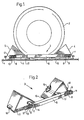
- fig. 1 shows a partially cut-up side view of an embodiment of a device according to the invention
- fig. 2 shows same in a partially cut-up perspective view
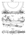
- fig. 3 shows in a manner equal to fig. 1 a second embodiment of the invention
- fig. 4 shows same in a perspective view together with an extension piece adapted for this embodiment
- fig. 5 shows a longitudinal section through the latter between the bar members of the first embodiment
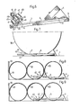
- fig. 6 shows a perspective view of a third embodiment of the invention
- fig. 7 shows a side view of the device according to fig. 6 used with a relatively large diameter object
- figs. 8 and 9 show side views of same used with relatively small diameter tubular objects.
- a cylindrical object 2 e.g. a vehicle wheel resting on a cargo supporting plane 1, said object being secured against rolling by means of a device 3 according to the present invention.
- This device includes two wedge- shaped blocks 4 and 5, which have their wedge apexes directed towards each other and are interconnected by means of two bar shaped members 6 and 7. At least a first of the bar members 6 is tubular and the second is telescopingly slidably inserted in the former. Between the two bar members acts a spring force tending to bring the blocks 4 and 5 towards each other.
- the second bar member 7 is tubular, and a pulling screw spring 8 is mounted within the two tubes guided in each other, such that it acts between the ends of the tubes where cylindrical spring pins 9 and 10, respectively, connect the spring ends to the respective tube by means of bores through opposite tube walls. plastic plugs 11 and 12 close the free tube ends off.
- the studs 13 and 14 are introduced through openings extending across the block 4 and 5, respectively. In their free ends the studs 13 and 14 are secured against being pulled out by means of hairpin locks 15.
- the tubes 6 and 7 have polygonal and preferably rectangular cross-sections to prevent mutual rotation of the tubes and the blocks.
- the tubes 6 and 7 have square cross-sections.
- the studs 13 and 14 and the openings therefor in the blocks 4 and 5 have polygonal and preferably rectangular cross-sections to prevent tilting of the blocks about the studs.
- the studs 13 and 14 have square cross-sections.
- the latter advantageously are provided with a layer 16 and 17, respectively, of rubber or the like material.
- the spring 8 is so weak that a person without effort can extend the telescoping bar arrangement from the shortest position shown in fig. 2, wherein the tube 6 abuts the stud 14, to such distance between the blocks 4 and 5 that these can be introduced on either side of an object 2, which is to be secured against rolling. Nevertheless, the spring 8 is so powerful that it is capable of moving the blocks 4 and 5 towards each other when they are unloaded, i.e. when their friction against the cargo supporting plane is relatively low. It is hereby ensured that if an object is moving in any direction, for instance as a consequence of braking, or comes into oscillation, the unloaded block will move closer to the other block provided the unloading be sufficiently great, i.e. if the distance between the blocks is or has become too large to keep the cargo sufficiently secured.
- the blocks 4 and 5 in this embodiment consisting of welded box structures of steel or aluminum, are provided with welded ears 18 against which a breaking tool, e.g. a crow bar, may be applied in order to raise a block from the cargo supporting plane and thereby lower the friction such that the block may be moved away from the object under extension of the telescopic bar system 6,7.
- a breaking tool e.g. a crow bar
- the invention comprises a second embodiment in which the length of travel can be varied.
- This embodiment is shown in figs. 3 to 5.
- the same reference numerals as in fig. 1 and 2 on details having their full correspondence therein, whereas details having similar function have the same reference numeral with a prime character.
- the blocks 4' and 5' shown in fig. 3 and 4 comprise extruded aluminum profiles, the inner of which, however, is not shown in detail.
- the ears 18' extend along the entire width of the blocks 4' and 5'.
- the resilient bar system is substantially similar to the one described above.
- the tube 6 and its stud 13 are unchanged as are the spring 8 and its connecting pins 9 and 10.
- the latter is located on a greater distance from the end of tube 7' than in the former embodiment.
- a snap-action spring 19 which by means of pin shaped ends 20, 21 extends through opposite bores in the tube 7' (figs. 3 and 5).
- the end of the tube 7' is introduced in a short tube 22 having the same cross-sectional dimensions as the tube 6. Close to the end of the tube 22 are opposite bores 23, 24 in the tube walls, into which the ends 20, 21 of the snap action spring 19 snap so that the tubes 7' and 22 are interconnected.
- the tube 22, is provided with a laterally extending stud 14', which in a similar manner as above is secured to the block 5' by means of a hair pin lock 15.
- the intermediate piece 25 comprises two tubes 26 and 27 telescopingly guided in each other, the tube 26 having the same cross-sectional dimensions as the tube 6 and the tube 27 having the same cross-sectional dimensions as the tube 7'.
- the intermediate piece 25 is shown in fig. 4 and its location between the tubes 7' and 22 is indicated by arrows.
- the principle for interconnection of the intermediate piece 25 between the tubes 7' .and 22 is shown more in detail in fig. 5.
- the tube 26 is provided with opposite bores 28 and 29, into which the ends 20 and 21 of the snap-action spring 19 are intended to snap upon introduction of the tube 7' into the tube 26, thereby to lock the tubes to each other.
- a snap-action spring 30 In the end of the tube 27 extending from the tube 26 is located a snap-action spring 30, the pin shaped ends 31 and 32 of which extend through opposite bores in the walls of the tube 27.
- the ends 31 and 32 of the snap action spring 30 are intended to snap into the bores 23 and 24 of the tube 22 when the tube 27 is introduced therein.
- the blocks, 4' and 5' may be positioned at a desired distance from each other by telescopic extension of the intermediate piece 25.
- the tube 26 is provided with a plurality of bores 33 and 34 extending through opposite tube walls, and the tube 27 is provided in its end opposite to the snap-action spring 30 with a similar snap-action spring 35, the ends 36 and 37 of which may snap into selective ones of the bores 33 and 34.
- rolling of a cylindrical object in one rolling direction could be desirable. That may be the case, e.g., when loading a plurality of paper rolls or tubes from the rear end of a railroad car or a lorry. In such case the objects are allowed to roll forward until restricted by a forward end wall or the like.
- the third embodiment of the invention is intended for use in such cases.
- the third embodiment of the invention is shown in figs. 6 to 9 and may utilize some basic parts of the first and/or second embodiment, viz. the telescoping bar members 6 and 7, the studs 13 and 14, respectively, extending therefrom, and the wedge shaped block 4 mounted on the stud 13.
- roller means 40 On the stud 14 of the tube 7 is mounted roller means 40, including two rolls 41 and 42. These rolls are individually and freely rotatable about axes parallel with the stud 14.
- the rolls 41 and 42 are rotatable about shafts 43 and 44, respectively, mounted between pairs of brackets 45, 46 and 47, 48, respectively, extending in opposite directions from a holder 49 which is unrotatably mounted on the stud 14.
- holder 49 is a tube, the inner cross-section of which corresponds to the outer cross-section of the stud 14 so that the holder 49 can be slid on the stud 14.
- hair-pin lock 15 secures the holder 49 on the stud 14. It is preferred that a plane through the shafts 43 and 44, in the mounted state of the roller means, forms an angle of 45° with the bar member 7.
- the device according to the third embodiment of the invention is applied about a cylindrical object in a manner corresponding to that of the former embodiments.
- a relatively large diameter object 50 such as a paper roll
- rolling to the right will be prevented by the wedge shaped block 4
- rolling to the left can take place due to contact between the object 50 and the roll 42 on one hand and between the roll 41 and the plane 1 on the other hand.
- the spring loaded telescoping bar members 6, 7 Upon rolling of the object 50 to the left the spring loaded telescoping bar members 6, 7 will extend slightly so as to unload block4 which will then be dragged along to the left.
- any obstacle preventing further rolling to the left such as an end wall of a railroad car or a previously loaded object, bouncing of the object 50 to the right will be effectively prevented by the block 4.
- figs. 8 and 9 is shown how the device according to the third embodiment of the invention can be used on tubular, relatively small diameter objects 51, 52, 53.
- the roller means 40 may be introduced inside one object 52, whereas the wedge shaped block 4 engages an adjacent object 53.
- Fig. 8 shows the situation when the object 52, upon the common travel of the objects 52 and 53 to the left, has just hit a previously loaded object 51, which rests against an end wall 54. In the next moment the object 53 will hit the object 52, and the spring force acting between the bar members 6 and 7 will ensure that the block 4 is kept close to the object 53 thus preventing any bouncing thereof to the right.
- the first and second embodiments of the invention easily converts into the third embodiment simply by substituting the roller means for one of the wedge shaped blocks.
- further examples of use include the use as parking blocks for airplanes and securing blocks for cars and trucks on board ferries.
Landscapes
- Engineering & Computer Science (AREA)
- Transportation (AREA)
- Mechanical Engineering (AREA)
- Rollers For Roller Conveyors For Transfer (AREA)
- Mutual Connection Of Rods And Tubes (AREA)
- Train Traffic Observation, Control, And Security (AREA)
- Handcart (AREA)
Claims (5)
Applications Claiming Priority (2)
| Application Number | Priority Date | Filing Date | Title |
|---|---|---|---|
| SE8401871A SE8401871D0 (sv) | 1984-04-04 | 1984-04-04 | Anordning for sekring av gods under transport |
| SE8402819 | 1984-05-24 |
Publications (3)
| Publication Number | Publication Date |
|---|---|
| EP0162829A2 EP0162829A2 (fr) | 1985-11-27 |
| EP0162829A3 EP0162829A3 (en) | 1988-02-10 |
| EP0162829B1 true EP0162829B1 (fr) | 1990-10-31 |
Family
ID=20355450
Family Applications (1)
| Application Number | Title | Priority Date | Filing Date |
|---|---|---|---|
| EP85850181A Expired EP0162829B1 (fr) | 1984-04-04 | 1985-05-22 | Dispositif limitant le mouvement d'objets cylindriques |
Country Status (5)
| Country | Link |
|---|---|
| US (1) | US4653967A (fr) |
| EP (1) | EP0162829B1 (fr) |
| AU (1) | AU580082B2 (fr) |
| CA (1) | CA1238525A (fr) |
| SE (1) | SE8401871D0 (fr) |
Families Citing this family (38)
| Publication number | Priority date | Publication date | Assignee | Title |
|---|---|---|---|---|
| USD328588S (en) | 1990-10-19 | 1992-08-11 | Mitchell Douglas G | Chock block unit |
| US5421625A (en) * | 1992-09-02 | 1995-06-06 | Arko; John K. | Automotive protective parking accessory |
| GB2271539B (en) * | 1992-10-17 | 1995-11-29 | Colin Twigger | Wheel clamping or chocking device |
| US5375965C1 (en) | 1993-01-25 | 2001-09-11 | Rite Hite Holding Corp | Vehicle restraining device |
| SE500210C2 (sv) * | 1993-06-09 | 1994-05-09 | Lars Johansson | Handtrucksparkerare |
| US5839863A (en) * | 1993-06-09 | 1998-11-24 | Ab Volvo | Handtruck parking device for securement on a transport vehicle |
| US5401129A (en) * | 1994-01-25 | 1995-03-28 | Area Transportation Co. | Trailer for hauling metal coils |
| ATE293078T1 (de) * | 1994-03-07 | 2005-04-15 | Rite Hite Holding Corp | Bremskeilpositionierungsvorrichtung, aktiviert durch das fahrzeug |
| US5577619A (en) * | 1994-07-01 | 1996-11-26 | Callahan; Eugene J. | Steel coil storage rack system |
| US5762459A (en) * | 1994-10-21 | 1998-06-09 | Rite-Hite Corporation | Wheel-activated vehicle restraint system |
| EP0905066B1 (fr) * | 1994-10-21 | 2003-05-14 | Rite-Hite Holding Corporation | Dispositif d'immobilisation d'un véhicule commandé par ses roues |
| FR2727659B1 (fr) * | 1994-12-05 | 1997-10-31 | Assidi Alain | Support de bouteille de gaz butane ou propane a usage domestique |
| US5515977A (en) * | 1995-08-10 | 1996-05-14 | Union Camp Corporation | Edge protecting packaging and distribution system for rolled laminar stock |
| AU680180B3 (en) * | 1996-05-23 | 1997-07-17 | Anthony George Porter | Support assembly |
| US6092970A (en) * | 1998-01-09 | 2000-07-25 | Rite-Hite Holding Corporation | Manually positioned wheel chocking apparatus |
| DE29815075U1 (de) * | 1998-08-21 | 1999-01-21 | Kögel Fahrzeugwerke AG, 89079 Ulm | Lastensicherungselement für eine Lastensicherungsschiene eines Transportfahrzeugs |
| GB2360831B (en) * | 2000-03-30 | 2003-11-05 | Gavin Cooper | Portagas |
| US6773221B2 (en) | 2001-07-05 | 2004-08-10 | Rite-Hite Holding Corporation | Positive locking mechanism for a wheel-activated vehicle restraint |
| US6948593B2 (en) * | 2003-08-13 | 2005-09-27 | Horton Steven K | Wheel chock |
| US6920771B1 (en) * | 2004-04-02 | 2005-07-26 | James Robert Griffith | Lock-down device for an all-terrain vehicle |
| DE102005012958A1 (de) * | 2005-03-12 | 2006-09-14 | Monika Andersen | Vorrichtung zur Sicherung von Ladung auf einer Ladefläche |
| GB0611320D0 (en) * | 2006-06-09 | 2006-07-19 | Cartwright & Sons Coach Builde | Support device for road transport vehicle |
| US8307956B2 (en) * | 2007-07-25 | 2012-11-13 | Rite-Hite Holding Corporation | Wheel chock system |
| US8006811B2 (en) | 2007-09-07 | 2011-08-30 | Rite-Hite Holding Corporation | Loading dock wheel restraint comprising a flexible elongate member |
| US8464846B2 (en) * | 2008-03-04 | 2013-06-18 | Rite-Hite Holding Corporation | Restraining arms for wheel chocks |
| DE202009000010U1 (de) | 2009-01-08 | 2009-03-12 | Schlobohm, Wolfgang | Ladungssicherungsmittel |
| US8286757B2 (en) | 2010-07-09 | 2012-10-16 | Rite-Hite Holding Corporation | Wheel chock system |
| US8851240B1 (en) * | 2012-05-17 | 2014-10-07 | Tommy G. Scoggins | Wheel chock and method |
| CN103661439A (zh) * | 2012-09-07 | 2014-03-26 | 长春宝钢钢材贸易有限公司 | 一种钢圆形卷材运输车 |
| CN103182979B (zh) * | 2013-03-30 | 2015-06-24 | 武汉科技大学 | 一种重型轧辊运输车 |
| CN103386920B (zh) * | 2013-08-04 | 2015-09-02 | 武汉科技大学 | 一种用轴颈夹紧的轧辊运输装置 |
| US10752154B2 (en) | 2015-11-30 | 2020-08-25 | Utc Overseas, Inc. | Modular systems and methods for transporting tower assembly of wind turbine |
| US9683546B1 (en) * | 2015-11-30 | 2017-06-20 | Utc Overseas, Inc. | Modular systems and methods for transporting tower assembly of wind turbine |
| SE539963C2 (en) * | 2016-05-18 | 2018-02-13 | Richard Vinnicombe Timothy | A device for immobilizing a wheeled vehicle |
| CN107472642A (zh) * | 2017-09-20 | 2017-12-15 | 重庆远望物流有限公司 | 一种物流运输托盘 |
| DE102019131009A1 (de) * | 2019-09-30 | 2021-04-01 | Liebherr-Hausgeräte Lienz Gmbh | Vorrichtung umfassend ein Kühl- und/oder Gefriergerät nebst Bodenpolster |
| IT202100017522A1 (it) * | 2021-07-02 | 2023-01-02 | Lokhen S R L | Dispositivo di supporto per cunei fermaruota e relativo kit comprendente il dispositivo di supporto per cunei fermaruota e almeno un cuneo fermaruota |
| IT202100031544A1 (it) * | 2021-12-16 | 2023-06-16 | Fa Bo Carr Srl | Dispositivo di supporto per carichi cilindrici, in particolare per bobine di grandi dimensioni |
Family Cites Families (12)
| Publication number | Priority date | Publication date | Assignee | Title |
|---|---|---|---|---|
| DE64771C (de) * | G. A. LUDEWIG in Dresden-Altstadt | Doppelter Radvorleger mit federnden Spannketten | ||
| US1407338A (en) * | 1920-07-29 | 1922-02-21 | Bruce E Skiles | Chock for automobile wheels |
| FR675784A (fr) * | 1929-05-25 | 1930-02-14 | Système de cales pour roues de véhicule | |
| FR1020804A (fr) * | 1952-01-24 | 1953-02-11 | Sncf | Plate-forme pour le transport de véhiucles |
| US2822063A (en) * | 1953-08-11 | 1958-02-04 | United Equipment & Service Inc | Self adjusting chock |
| US2720285A (en) * | 1955-01-12 | 1955-10-11 | Bert L Taylor | Safety wheel chock |
| DE1034102B (de) * | 1956-10-23 | 1958-07-10 | Kloeckner Humboldt Deutz Ag | Bremsschuh zum Festhalten von Strassenfahrzeugen auf Eisenbahnwagen |
| US3260219A (en) * | 1964-06-05 | 1966-07-12 | A J Ind Inc | Conveyor structure |
| US3338338A (en) * | 1965-10-22 | 1967-08-29 | Victor W Lindeen | Vehicle wheel blocks |
| GB1178466A (en) * | 1966-03-01 | 1970-01-21 | Philip Chambers | Apparatus for Positioning a Load on a Carrier |
| US3596605A (en) * | 1968-10-24 | 1971-08-03 | Richard J Shelstad | Conveyor mechanism |
| AU444778B1 (en) * | 1969-10-21 | 1972-04-13 | James Slater Leslie | Releasable chocking apparatus |
-
1984
- 1984-04-04 SE SE8401871A patent/SE8401871D0/xx unknown
-
1985
- 1985-05-22 EP EP85850181A patent/EP0162829B1/fr not_active Expired
- 1985-05-24 CA CA000482348A patent/CA1238525A/fr not_active Expired
- 1985-05-24 US US06/737,640 patent/US4653967A/en not_active Expired - Fee Related
- 1985-08-01 AU AU45694/85A patent/AU580082B2/en not_active Ceased
Also Published As
| Publication number | Publication date |
|---|---|
| EP0162829A2 (fr) | 1985-11-27 |
| EP0162829A3 (en) | 1988-02-10 |
| SE8401871D0 (sv) | 1984-04-04 |
| AU580082B2 (en) | 1988-12-22 |
| CA1238525A (fr) | 1988-06-28 |
| AU4569485A (en) | 1987-02-05 |
| US4653967A (en) | 1987-03-31 |
Similar Documents
| Publication | Publication Date | Title |
|---|---|---|
| EP0162829B1 (fr) | Dispositif limitant le mouvement d'objets cylindriques | |
| CA1272230A (fr) | Remorque a benne basculante chevauchant la charge | |
| CA2006605A1 (fr) | Wagon plat articule pour le transport de remorques | |
| US4923360A (en) | Collapsible tailgate ramp | |
| US6626475B2 (en) | Trailer-mounted, side entry bar apparatus | |
| US5845971A (en) | Side dump trailer | |
| US3317006A (en) | Folding wheel chock | |
| US3858690A (en) | Chock | |
| US5497857A (en) | Emergency brake system for wheeled vehicles | |
| JP2006132172A (ja) | 車両強制停止装置と該装置を使用した車両強制停止方法 | |
| US5435418A (en) | Emergency brake system for wheeled vehicles | |
| US4589670A (en) | Convertible truck/trailer assembly and method | |
| US3420390A (en) | Transfer trailer drawbar device | |
| DE29809358U1 (de) | Vorrichtung zur Steigerung der passiven und aktiven Sicherheit von Kraftfahrzeugen | |
| US4750785A (en) | Truss transportation trailer | |
| US3610690A (en) | Support arrangement for truck body | |
| US10759321B1 (en) | Extendable trailer | |
| EP1813497A1 (fr) | Système de transport combiné pour les marchandises par train et sur route | |
| US3480296A (en) | Trailer hitch | |
| US3692331A (en) | Load transfer coupling mechanism | |
| US5746157A (en) | Vehicle-mounted animal restraint apparatus | |
| US7946606B2 (en) | Converter dolly backup device | |
| US5267749A (en) | Vehicular truck trailer brake apparatus | |
| US4362312A (en) | Reach compensator for logging truck and trailer | |
| US6474676B1 (en) | Universal tow bar |
Legal Events
| Date | Code | Title | Description |
|---|---|---|---|
| PUAI | Public reference made under article 153(3) epc to a published international application that has entered the european phase |
Free format text: ORIGINAL CODE: 0009012 |
|
| AK | Designated contracting states |
Designated state(s): BE CH DE FR GB LI NL SE |
|
| PUAL | Search report despatched |
Free format text: ORIGINAL CODE: 0009013 |
|
| AK | Designated contracting states |
Kind code of ref document: A3 Designated state(s): BE CH DE FR GB LI NL SE |
|
| 17P | Request for examination filed |
Effective date: 19880803 |
|
| 17Q | First examination report despatched |
Effective date: 19890306 |
|
| GRAA | (expected) grant |
Free format text: ORIGINAL CODE: 0009210 |
|
| AK | Designated contracting states |
Kind code of ref document: B1 Designated state(s): BE CH DE FR GB LI NL SE |
|
| REF | Corresponds to: |
Ref document number: 3580303 Country of ref document: DE Date of ref document: 19901206 |
|
| ET | Fr: translation filed | ||
| PLBE | No opposition filed within time limit |
Free format text: ORIGINAL CODE: 0009261 |
|
| STAA | Information on the status of an ep patent application or granted ep patent |
Free format text: STATUS: NO OPPOSITION FILED WITHIN TIME LIMIT |
|
| 26N | No opposition filed | ||
| EAL | Se: european patent in force in sweden |
Ref document number: 85850181.0 |
|
| PGFP | Annual fee paid to national office [announced via postgrant information from national office to epo] |
Ref country code: GB Payment date: 19970506 Year of fee payment: 13 |
|
| PGFP | Annual fee paid to national office [announced via postgrant information from national office to epo] |
Ref country code: FR Payment date: 19970513 Year of fee payment: 13 |
|
| PGFP | Annual fee paid to national office [announced via postgrant information from national office to epo] |
Ref country code: DE Payment date: 19970516 Year of fee payment: 13 |
|
| PGFP | Annual fee paid to national office [announced via postgrant information from national office to epo] |
Ref country code: CH Payment date: 19970522 Year of fee payment: 13 |
|
| PGFP | Annual fee paid to national office [announced via postgrant information from national office to epo] |
Ref country code: BE Payment date: 19970528 Year of fee payment: 13 |
|
| PGFP | Annual fee paid to national office [announced via postgrant information from national office to epo] |
Ref country code: NL Payment date: 19970531 Year of fee payment: 13 |
|
| PG25 | Lapsed in a contracting state [announced via postgrant information from national office to epo] |
Ref country code: GB Free format text: LAPSE BECAUSE OF NON-PAYMENT OF DUE FEES Effective date: 19980522 |
|
| PG25 | Lapsed in a contracting state [announced via postgrant information from national office to epo] |
Ref country code: LI Free format text: LAPSE BECAUSE OF NON-PAYMENT OF DUE FEES Effective date: 19980531 Ref country code: FR Free format text: LAPSE BECAUSE OF NON-PAYMENT OF DUE FEES Effective date: 19980531 Ref country code: CH Free format text: LAPSE BECAUSE OF NON-PAYMENT OF DUE FEES Effective date: 19980531 Ref country code: BE Free format text: LAPSE BECAUSE OF NON-PAYMENT OF DUE FEES Effective date: 19980531 |
|
| BERE | Be: lapsed |
Owner name: STEIDING LENNART Effective date: 19980531 Owner name: ISAKSSON BERTIL Effective date: 19980531 |
|
| PG25 | Lapsed in a contracting state [announced via postgrant information from national office to epo] |
Ref country code: NL Free format text: LAPSE BECAUSE OF NON-PAYMENT OF DUE FEES Effective date: 19981201 |
|
| GBPC | Gb: european patent ceased through non-payment of renewal fee |
Effective date: 19980522 |
|
| REG | Reference to a national code |
Ref country code: CH Ref legal event code: PL |
|
| NLV4 | Nl: lapsed or anulled due to non-payment of the annual fee |
Effective date: 19981201 |
|
| PG25 | Lapsed in a contracting state [announced via postgrant information from national office to epo] |
Ref country code: DE Free format text: LAPSE BECAUSE OF NON-PAYMENT OF DUE FEES Effective date: 19990302 |
|
| REG | Reference to a national code |
Ref country code: FR Ref legal event code: ST |
|
| PGFP | Annual fee paid to national office [announced via postgrant information from national office to epo] |
Ref country code: SE Payment date: 20030328 Year of fee payment: 19 |
|
| PG25 | Lapsed in a contracting state [announced via postgrant information from national office to epo] |
Ref country code: SE Free format text: LAPSE BECAUSE OF NON-PAYMENT OF DUE FEES Effective date: 20040523 |
|
| EUG | Se: european patent has lapsed |