EP0162321A1 - Dispositif d'enregistrement d'image à haute vitesse pour traitement d'énergie par soustraction - Google Patents
Dispositif d'enregistrement d'image à haute vitesse pour traitement d'énergie par soustraction Download PDFInfo
- Publication number
- EP0162321A1 EP0162321A1 EP85104982A EP85104982A EP0162321A1 EP 0162321 A1 EP0162321 A1 EP 0162321A1 EP 85104982 A EP85104982 A EP 85104982A EP 85104982 A EP85104982 A EP 85104982A EP 0162321 A1 EP0162321 A1 EP 0162321A1
- Authority
- EP
- European Patent Office
- Prior art keywords
- radiation
- filter
- image recording
- stimulable phosphor
- image
- Prior art date
- Legal status (The legal status is an assumption and is not a legal conclusion. Google has not performed a legal analysis and makes no representation as to the accuracy of the status listed.)
- Granted
Links
Images

Classifications
-
- G—PHYSICS
- G03—PHOTOGRAPHY; CINEMATOGRAPHY; ANALOGOUS TECHNIQUES USING WAVES OTHER THAN OPTICAL WAVES; ELECTROGRAPHY; HOLOGRAPHY
- G03B—APPARATUS OR ARRANGEMENTS FOR TAKING PHOTOGRAPHS OR FOR PROJECTING OR VIEWING THEM; APPARATUS OR ARRANGEMENTS EMPLOYING ANALOGOUS TECHNIQUES USING WAVES OTHER THAN OPTICAL WAVES; ACCESSORIES THEREFOR
- G03B42/00—Obtaining records using waves other than optical waves; Visualisation of such records by using optical means
- G03B42/02—Obtaining records using waves other than optical waves; Visualisation of such records by using optical means using X-rays
- G03B42/021—Apparatus for direct X-ray cinematography
Definitions
- This invention relates to an apparatus for recording original images of an object subjected to a digital subtraction processing for radiation images conducted by use of stimulable phosphor sheets.
- This invention particularly relates to a high-speed image recording apparatus for recording radiation images by quickly changing radiation filters.
- a digital subtraction processing method is used for processing radiation images.
- two radiation images recorded under conditions different from each other are photoelectrically read out to obtain digital image signals, which are then subjected to a subtraction processing with respect to the corresponding picture elements of the images, thereby to obtain a difference signal for forming an image of a specific structure contained in the radiation images.
- the method makes it possible to reproduce a radiation image of only the specific structure by use of the signal thus obtained.
- subtraction processing is classified into the so-called temporal (time difference) subtraction processing method and the so-called energy subtraction processing method.
- the image of a specific structure is extracted by subtracting the image signal of a radiation image obtained without injection _of contrast media from the image signal of a radiation image in which the image of the specific structure enhanced by the injection of contrast media.
- an object is exposed to radiations having energy distributions different from each other to obtain two radiation images respectively containing the images of a specific structure recorded on the basis of the intrinsic radiation energy absorption characteristics of the specific structure. Then; the image signals of the two radiation images are weighted appropriately when necessary, and subjected to subtraction to extract the image of the specific structure.
- the processing technique is specifically called the digital subtraction processing method, or more commonly, digital radiography (abbreviated as "DR").
- a novel digital subtraction processing method has been proposed, for example, in Japanese Unexamined Patent Publication No..58(1983)-163340.
- the method comprises the steps of (i) using two or more stimulable phosphor sheets exhibiting an extremely wide latitude of exposure to a radiation, (ii) exposing the stimulable phosphor sheets to the radiation passing through the same object under different conditions to have radiation images of the object stored in the stimulable phosphor sheets, image information on the specific structure being different between the radiation images, (iii) detecting the radiation images by scanning with stimulating rays to obtain digital image signals, and (iv) conducting a digital subtraction processing by use of the digital image signals.
- the stimulable phosphor sheets comprise a stimulable phosphor which is able to store a part of the radiation energy when exposed to a radiation such as X - rays, ⁇ -rays, ⁇ -rays, ⁇ -rays, cathode rays or ultraviolet rays, and then emits light in proportion to the stored energy of the radiation when exposed to stimulating rays such as visible light, as disclosed for example in U . S . Patent No. 4,258,264.
- the stimulable phosphor sheets exhibit an extremely wide latitude of exposure and a markedly high resolving power.
- the digital subtraction processing is conducted by use of the radiation images stored in the stimulable phosphor sheets, it is possible to obtain a radiation image having an improved image quality, particularly a high diagnostic efficiency and accuracy, regardless of the amount of radiation to which the stimulable phosphor sheets are exposed.
- the stimulable phosphor sheets are changed quickly at the image recording position and are exposed to a radiation of high energy and a radiation of low energy passing through an object by quickly changing over the tube voltage of an X-ray tube to have radiation images of the object stored in the respective stimulable phosphor sheets.
- this method is hereinafter called the double exposure method.
- the double exposure method in order to prevent a motion artifact from being generated by an object motion, the two radiation exposure steps are conducted at as short time intervals as possible.
- the primary object of the present invention is to provide a high-speed image recording apparatus which records a high energy image and a low energy image of good energy discrimination by use of radiation filters.
- Another object of the present invention is to provide a high-speed image recording apparatus which records a high energy image and a low energy image at very short time intervals.
- the present invention provides a high-speed image recording apparatus for an energy subtraction processing, which comprises:
- the present invention it is possible to obtain a high energy image and a low energy image of good energy discrimination by automatically changing over the radiation filter at very short time intervals. Therefore, it becomes possible to form a noise-free subtraction image in which an unnecessary portion is erased completely and which has an improved image quality, particularly a high diagnostic efficiency and accuracy. Also, since original radiation images are recorded very quickly, generation of a motion artifact is prevented securely.
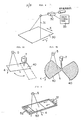
- a sheet changer 2 is provided with an image recording table 1 at the upper portion, and a stimulable phosphor sheet A is positioned at an image recording position T' standing face to face with an object 3 with the image recording table 1 intervening therebetween.
- the sheet changer 2 removes the stimulable phosphor sheet A from the image recording position T and moves a stimulable phosphor sheet B in a waiting position W to the image record: position T.
- the sheet changer 2 sequentially loads unexposed stimulable phosphor sheets to the image recording position T.
- An X-ray source 5 for emitting X-rays 4 to the stimulable phosphor sheet A at the image recording position T is positioned above the image recording table 1.
- the tube voltage of the X-ray source 5 is adjusted to a desired value by an X-ray source drive controller 6.
- An X-ray filter plate 8 switchable by a filter change-over device 7 is positioned on the passage of the X-rays 4 between the X-ray source 5 and the object 3.
- the X-ray filter plate 8 is provided with a high energy range pass filter 8A fabricated of a copper plate or the like and a low energy range pass filter 8B fabricated of La, Y or the like and generally called a K edge filter.
- the X-ray filter plate 8 is rotated by the filter chanae - over device 7 so that one of the high energy range pass filter 8A and the low energy range pass filter 8B is selectively positioned on the passage of the X-rays 4 at each image recording step.
- Heartbeats of the object 3 are detected by a heartbeat meter 9, and a heartbeat signal S1 generated by the heartbeat meter 9 is sent to a controller 10.
- the controller 10 sends a sheet change signal S2, a filter change-over signal S3 and an X-ray emission signal S4 respectively to the sheet changer 2, the filter change-over device 7 and the X-ray source drive controller 6.
- the apparatus shown in Figure 1 is operated as described below.
- the controller 10 sends the sheet change signal S2 and the filter change-over signal S3 respectively to the sheet changer 2 and the filter change-over device 7 to move the stimulable phosphor sheet A to the image recording position T and to position the high energy range pass filter 8A on the passage of the X-rays 4.
- the aforesaid operations may be conducted before the object 3 lies on the image recording table 1 or may be conducted manually without using the controller 10.
- the controller 10 sends the X-ray emission signal S4 to the X-ray source drive controller 6 in synchronization with the predetermined heartbeat timing on the basis of the heartbeat signal Sl and drives the X-ray source 5 at a comparatively high tube voltage, for example, at .120kVp.
- the X-rays 4 of comparatively high energy thisemitted pass through the high energy range pass filter 8A, and X-rays of a comparatively low energy range contained in the X-rays 4, if any, are cut off by the filter 8A. In this manner, an X-ray image of the object is stored in the stimulable phosphor sheet A only by the X-rays 4 of a comparatively high energy range.
- the controller 10 sends the sheet change signal S2 to the sheet changer 2 to remove the stimulable phosphor sheet A from the image recording position T and moves the next stimulable phosphor sheet B to the image recording position T.
- the controller 10 sends the filter change-over signal S3 to the filter change-over device 7 to position the low energy range pass filter 8B instead of the high energy range pass filter 8A on the X-ray passage.
- the controller 10 sends the X-ray emission signal S4 to the X-ray source drive controller 6 at the same timing as the predetermined heartbeat timing to drive the X-ray source 5 at a comparatively low tube voltage, for example, at 60kVp.
- an X-ray image of the object 3 is stored in the stimulable phosphor sheet B only by the X-rays 4 of the low energy range passing through the filter 8B.
- the image information on a specific structure of the object 3 differs since the specific structure exhibits inherent X-ray energy absorption characteristics.
- a subtraction processing for extracting the image of the specific structure will be briefly described below.
- the X-ray images are read out by use of an image read-out means as shown in Figure 3 to obtain digital image signals representing the X-ray images.
- a laser beam 11 emitted by a laser beam source 20 is deflected in the direction as indicated by the arrow X by a scanning mirror 12 to conduct main scanning.
- the stimulable phosphor sheet A is caused to release the X-ray energy stored therein as light 13 in proportion to the X-ray energy.
- the emitted light 13 enters a light guide member 14, which is made by forming a transparent acrylic sheet, from one end face thereof.
- the light guide member 14 may be of a shape and a material as disclosed in U.S. Patent No. 4,346,295.
- the light 13 is then guided through total reflection inside of the light guide member 14 up to a photomultiplier 15, and the amount of the light 13 is outputted as an image signal S by the photomultiplier 15.
- the image signal S is then converted into a digital image signal logSA of a logarithmic value (logS) by a log- converter 16 comprising an amplifier and an A/D converter.
- the digital image signal logSA is stored in a storage medium 17 such as a magnetic tape. Thereafter, the X-ray image stored in the other stimulable phosphor sheet B is read out therefrom in exactly the same manner as described above, and digital image signal logSB thus obtained is stored in the storage medium 17.
- a subtraction processing is conducted by use of the digital image signals logSA and logSB obtained as described above.
- the digital image signals logSA and logSB are read respectively from the storage medium 17, and are sent to a subtraction operation circuit 18.
- the subtraction operation circuit 18 weights the digital image signals logSA and logSB obtained as described above by use of weight factors a and b, and conducts a subtraction processing between the digital image signals logSA and logSB with respect to the corresponding picture elements to obtain a digital difference signal Ssub as expressed by where a, b and c are constants.
- the constant c is a bias component for adjusting the density of the difference signal Ssub approximately to a predetermined value.
- the difference signal Ssub is subjected to a signal processing such as a gradation processing, and is then sent to an image reproducing apparatus, for example, a display device such as a cathode ray tube (CRT) or a point-by-point scanning apparatus which reproduces a subtraction image by use of the difference signal Ssub.
- an image reproducing apparatus for example, a display device such as a cathode ray tube (CRT) or a point-by-point scanning apparatus which reproduces a subtraction image by use of the difference signal Ssub.
- Figure 4 shows an apparatus for reproducing the image by point-by-point scanning as an example of the subtraction image reproducing system.
- a photosensitive film 30 is moved in the sub-scanning direction as indicated by the arrow Y, and at the same time a laser beam 31 is deflected onto the photosensitive film 30 in the main scanning direction as indicated by the arrow X.
- the laser beam 31 is modulated by an A/O modulator 32 with an image signal sent from an image signal feeder 33, thereby to form a visible image on the photosensitive film 30.
- the difference signal Ssub as the modulating image signal, it is possible to reproduce a visible image, wherein only the specific structure is extracted by the digital subtraction processing, on the photosensitive film 30.
- the two original images subjected to the energy subtraction processing i.e. the high energy image stored in the stimulable phosphor sheet A and the low energy image stored in the stimulable phosphor sheet B, are recorded by the X-rays of energy ranges separated securely from each other by the action of the high energy range pass filter 8A and the low energy range pass filter 8B. Therefore, in the obtained subtraction image, an unnecessary image portion is securely erased and the level of noise is low.
- the X-ray exposure operation is not limited to the sequence of the high energy X-rays and the low energy X-rays, and may be of the sequence of the low energy X-rays and the high energy X-rays.
- the change of the stimulable phosphor sheets A and B, change-over of the filters 8A and BB, and the intermittent activation of the X-ray source 5 can be conducted within approximately 0.3 second, it is possible to record the high energy image and the low energy image between two consecutive heartbeats, and to record the original images exhibiting no motion artifact after the subtraction processing.
- the high energy range pass filter 8A and the low energy range pass filter 8B When materials exhibiting high energy discrimination capacity are used as the high energy range pass filter 8A and the low energy range pass filter 8B, it becomes possible to obtain the high energy image and the low energy image without changing the tube voltage of the X-ray source 5. Also, instead of using the radiation filters for high energy range pass and low energy range pass, only one of them may be used. In this case, in general, the high energy range pass filter should preferably be used instead of the low energy range pass filter.
- a slidable radiation filter 50 as shown in Figure 6 which is attracted by an electromagnet 51 and removed from the radiation passage at the first image recording step and is pulled by a spring 52 and is positioned on the radiation passage at the second image recording step when the electromagnet 51 is demagnetized.
- the present invention embraces the case where only one type of the radiation filter is used. Accordingly, when only one type of the radiation filter is used, the term "changing over a different radiation filter on a radiation passage at each image recording step" as used herein means that the condition of the filter positioned on the radiation passage and the condition of the filter absent on the radiation passage are switched at each image recording step.
- radiation exposure need not necessarily be synchronized with heartbeats of the object.
- radiation exposure should preferably be synchronized with the heartbeats since generation of a motion artifact caused by the heartbeats is prevented.
- Image recording in synchronization with the heartbeats may be conducted also by driving the radiation source by & synchronizing signal obtained from the heartbeat signal and sending the filter change-over signal and the sheet change signal respectively to the radiation filter change-over device and the sheet changer at timing after the synchronizing signal, thereby changing over the filter and the stimulable phosphor sheet.
- the position of the radiation filter is not limited to the position on the X-ray passage between the X-ray source and the object.
- the radiation filter may be positioned on the X-ray passage between the object and the stimulable phosphor sheet.
- the radiation filter should preferably be positioned between the X-ray source and the object, and should more preferably be positioned close to the X-ray source as shown in Figure 1.
Landscapes
- Physics & Mathematics (AREA)
- General Physics & Mathematics (AREA)
- Apparatus For Radiation Diagnosis (AREA)
- X-Ray Techniques (AREA)
- Analysing Materials By The Use Of Radiation (AREA)
- Measurement Of Radiation (AREA)
- Radiography Using Non-Light Waves (AREA)
Applications Claiming Priority (2)
| Application Number | Priority Date | Filing Date | Title |
|---|---|---|---|
| JP82350/84 | 1984-04-24 | ||
| JP59082350A JPS60225541A (ja) | 1984-04-24 | 1984-04-24 | エネルギ−サブトラクシヨン用高速撮影装置 |
Publications (2)
| Publication Number | Publication Date |
|---|---|
| EP0162321A1 true EP0162321A1 (fr) | 1985-11-27 |
| EP0162321B1 EP0162321B1 (fr) | 1988-11-09 |
Family
ID=13772116
Family Applications (1)
| Application Number | Title | Priority Date | Filing Date |
|---|---|---|---|
| EP85104982A Expired EP0162321B1 (fr) | 1984-04-24 | 1985-04-24 | Dispositif d'enregistrement d'image à haute vitesse pour traitement d'énergie par soustraction |
Country Status (4)
| Country | Link |
|---|---|
| US (1) | US4896037A (fr) |
| EP (1) | EP0162321B1 (fr) |
| JP (1) | JPS60225541A (fr) |
| DE (1) | DE3566171D1 (fr) |
Cited By (2)
| Publication number | Priority date | Publication date | Assignee | Title |
|---|---|---|---|---|
| GB2365522A (en) * | 2000-08-03 | 2002-02-20 | Cambridge Imaging Ltd | X-ray inspection and material discrimination |
| US7502442B2 (en) | 2002-01-28 | 2009-03-10 | Smiths Heimann Gmbh | X-ray inspection system and method |
Families Citing this family (39)
| Publication number | Priority date | Publication date | Assignee | Title |
|---|---|---|---|---|
| JP2557265B2 (ja) * | 1989-04-20 | 1996-11-27 | 富士写真フイルム株式会社 | エネルギーサブトラクション方法 |
| EP0418921B1 (fr) * | 1989-09-22 | 1998-12-16 | Fuji Photo Film Co., Ltd. | Méthode et appareil de traitement de soustraction d'énergie, méthode et appareil de traitement de superposition et appareil de lecture d'image de radiation |
| JP2574181B2 (ja) * | 1989-10-19 | 1997-01-22 | 富士写真フイルム株式会社 | 異常陰影検出装置 |
| US5485371A (en) | 1990-02-14 | 1996-01-16 | Fuji Photo Film Co., Ltd. | Method for forming energy subtraction radiation images, and method and apparatus for smoothing radiation images |
| JP2627097B2 (ja) * | 1990-04-04 | 1997-07-02 | 富士写真フイルム株式会社 | エネルギーサブトラクション画像生成方法および装置 |
| US5081660A (en) * | 1990-06-06 | 1992-01-14 | Yokio Fujisaki | High resolution x-ray imaging system with energy fluctuation restricting filters |
| US6113587A (en) | 1990-09-24 | 2000-09-05 | Plc Medical Systems, Inc. | Handpiece for a medical laser system |
| JP2952428B2 (ja) * | 1990-10-18 | 1999-09-27 | 富士写真フイルム株式会社 | 放射線画像のエネルギーサブトラクション方法および装置 |
| JP2640582B2 (ja) * | 1991-04-18 | 1997-08-13 | 富士写真フイルム株式会社 | エネルギーサブトラクション画像生成方法 |
| US5402338A (en) * | 1991-12-26 | 1995-03-28 | Fuji Photo Film Co., Ltd. | Method for forming energy subtraction images |
| US5195121A (en) * | 1992-01-22 | 1993-03-16 | B.C. Medical Ltd. | X-ray beam modulator |
| JPH08294054A (ja) * | 1995-04-20 | 1996-11-05 | Fuji Photo Film Co Ltd | エネルギーサブトラクション処理方法および装置 |
| US5680435A (en) * | 1995-09-22 | 1997-10-21 | Siemens Aktiengesellschaft | X-ray diagnostic apparatus with a filter device |
| JP3901770B2 (ja) * | 1996-10-21 | 2007-04-04 | 富士フイルム株式会社 | エネルギーサブトラクション処理方法および装置 |
| US6125166A (en) * | 1998-01-13 | 2000-09-26 | Fuji Photo Film Co., Ltd. | Method of forming energy subtraction images |
| US6278760B1 (en) | 1998-11-13 | 2001-08-21 | Fuji Photo Film Co., Ltd. | Radiation image forming method and apparatus |
| US6392237B1 (en) | 1999-02-08 | 2002-05-21 | Fuji Photo Film Co., Ltd. | Method and apparatus for obtaining radiation image data |
| US7123759B1 (en) * | 1999-06-30 | 2006-10-17 | Fuji Photo Film Co., Ltd. | Image transfer and output method and system using the same |
| US6495851B1 (en) | 1999-06-30 | 2002-12-17 | Fuji Photo Film Co., Ltd. | Radiation image information read-out method and apparatus |
| US6628434B1 (en) | 1999-07-12 | 2003-09-30 | Fuji Photo Film Co., Ltd. | Method and system for image transfer and image signal output apparatus and terminal used therefor |
| DE19962773A1 (de) * | 1999-12-23 | 2001-07-26 | Agfa Gevaert Ag | Vorrichtung zum Auslesen von in einer Speicherschicht abgespeicherten Informationen sowie Röntgenkassette und Röntgentisch |
| JP2002084459A (ja) | 2000-09-11 | 2002-03-22 | Fuji Photo Film Co Ltd | 放射線画像情報読取方法および装置 |
| US6421419B1 (en) | 2000-11-08 | 2002-07-16 | Fuji Photo Film Co., Ltd. | Energy subtraction processing method and apparatus |
| JP2002197440A (ja) * | 2000-12-27 | 2002-07-12 | Fuji Photo Film Co Ltd | 放射線画像データ処理方法および装置 |
| JP4397532B2 (ja) * | 2001-01-10 | 2010-01-13 | 富士フイルム株式会社 | 画像データ取扱方法および装置 |
| JP2002216106A (ja) * | 2001-01-16 | 2002-08-02 | Fuji Photo Film Co Ltd | エネルギーサブトラクション画像生成方法および装置 |
| JP2002216107A (ja) * | 2001-01-16 | 2002-08-02 | Fuji Photo Film Co Ltd | 画像データ圧縮方法および装置 |
| US7248726B2 (en) * | 2001-03-21 | 2007-07-24 | Fujifilm Corporation | Energy subtraction processing method and apparatus |
| US7834321B2 (en) * | 2006-07-14 | 2010-11-16 | Carestream Health, Inc. | Apparatus for asymmetric dual-screen digital radiography |
| JP4575909B2 (ja) * | 2006-11-22 | 2010-11-04 | ジーイー・メディカル・システムズ・グローバル・テクノロジー・カンパニー・エルエルシー | X線断層撮影装置 |
| US9991014B1 (en) * | 2014-09-23 | 2018-06-05 | Daniel Gelbart | Fast positionable X-ray filter |
| US10849576B2 (en) | 2017-04-27 | 2020-12-01 | Medtronic Navigation, Inc. | Filter system and method for imaging a subject |
| US10806413B2 (en) | 2017-04-27 | 2020-10-20 | Medtronic Navigation, Inc. | Filter system and method for imaging a subject |
| US10682103B2 (en) | 2017-04-27 | 2020-06-16 | Medtronic Navigation, Inc. | Filter system and method for imaging a subject |
| JP2020521521A (ja) * | 2017-04-27 | 2020-07-27 | メドトロニック・ナビゲーション,インコーポレーテッド | 対象を画像化するためのフィルタシステムおよび方法 |
| US10881371B2 (en) | 2018-12-27 | 2021-01-05 | Medtronic Navigation, Inc. | System and method for imaging a subject |
| US11071507B2 (en) | 2018-12-27 | 2021-07-27 | Medtronic Navigation, Inc. | System and method for imaging a subject |
| US10888294B2 (en) | 2018-12-27 | 2021-01-12 | Medtronic Navigation, Inc. | System and method for imaging a subject |
| CN110720943B (zh) * | 2019-12-19 | 2020-04-10 | 深圳市创谷科技发展有限公司 | 限束器及x光机 |
Citations (7)
| Publication number | Priority date | Publication date | Assignee | Title |
|---|---|---|---|---|
| US3854049A (en) * | 1973-12-10 | 1974-12-10 | Wisconsin Alumni Res Found | Compensation for patient thickness variations in differential x-ray transmission imaging |
| US3974386A (en) * | 1974-07-12 | 1976-08-10 | Wisconsin Alumni Research Foundation | Differential X-ray method and apparatus |
| US4199687A (en) * | 1977-08-31 | 1980-04-22 | Siemens Aktiengesellschaft | Sheet film changer |
| US4258264A (en) * | 1978-07-12 | 1981-03-24 | Fuji Photo Film Co., Ltd. | Method of and apparatus for reading out a radiation image recorded in a stimulable phosphor |
| US4276473A (en) * | 1979-02-28 | 1981-06-30 | Fuji Photo Film Co., Ltd. | Gradation processing method and apparatus for radiation image recording system |
| US4310886A (en) * | 1978-12-26 | 1982-01-12 | Fuji Photo Film, Co. Ltd. | Image gradation processing method and apparatus for radiation image recording system |
| US4387428A (en) * | 1979-12-25 | 1983-06-07 | Fuji Photo Film Co., Ltd. | Method of and apparatus for processing a radiation image |
Family Cites Families (13)
| Publication number | Priority date | Publication date | Assignee | Title |
|---|---|---|---|---|
| DE587389C (de) * | 1932-07-07 | 1933-11-03 | Robert Janker Dr | Elektrische Filterbetaetigung in Roentgenanlagen |
| US3418475A (en) * | 1965-08-19 | 1968-12-24 | Claude R. Hudgens | Leaf spring-mounted shutter device activated by the interruption of electrical power |
| US4346295A (en) * | 1978-12-26 | 1982-08-24 | Fuji Photo Film Co., Ltd. | Radiation image read out device |
| JPS5643784U (fr) * | 1979-09-11 | 1981-04-21 | ||
| US4361762A (en) * | 1980-07-30 | 1982-11-30 | Rca Corporation | Apparatus and method for neutralizing the beam in an ion implanter |
| US4399550A (en) * | 1981-02-27 | 1983-08-16 | General Electric Company | Spinning filter for X-ray apparatus |
| DE3124583A1 (de) * | 1981-06-23 | 1982-12-30 | Siemens AG, 1000 Berlin und 8000 München | Roentgendiagnostikeinrichtung zur darstellung von organen |
| JPS58163340A (ja) * | 1982-03-20 | 1983-09-28 | 富士写真フイルム株式会社 | 放射線画像のサブトラクシヨン処理方法 |
| JPS5932440A (ja) * | 1982-08-17 | 1984-02-21 | 富士写真フイルム株式会社 | 放射線画像のサブトラクシヨン処理方法 |
| DE3366802D1 (en) * | 1982-03-20 | 1986-11-13 | Fuji Photo Film Co Ltd | Subtraction processing method and apparatus for radiation images |
| US4482918A (en) * | 1982-04-26 | 1984-11-13 | General Electric Company | Method and apparatus for X-ray image subtraction |
| JPS5945A (ja) * | 1982-06-22 | 1984-01-05 | 株式会社東芝 | X線撮影装置 |
| JPS5936242A (ja) * | 1982-08-24 | 1984-02-28 | Toshiba Corp | X線診断装置 |
-
1984
- 1984-04-24 JP JP59082350A patent/JPS60225541A/ja active Pending
-
1985
- 1985-04-24 EP EP85104982A patent/EP0162321B1/fr not_active Expired
- 1985-04-24 DE DE8585104982T patent/DE3566171D1/de not_active Expired
-
1986
- 1986-09-25 US US06/912,208 patent/US4896037A/en not_active Expired - Lifetime
Patent Citations (7)
| Publication number | Priority date | Publication date | Assignee | Title |
|---|---|---|---|---|
| US3854049A (en) * | 1973-12-10 | 1974-12-10 | Wisconsin Alumni Res Found | Compensation for patient thickness variations in differential x-ray transmission imaging |
| US3974386A (en) * | 1974-07-12 | 1976-08-10 | Wisconsin Alumni Research Foundation | Differential X-ray method and apparatus |
| US4199687A (en) * | 1977-08-31 | 1980-04-22 | Siemens Aktiengesellschaft | Sheet film changer |
| US4258264A (en) * | 1978-07-12 | 1981-03-24 | Fuji Photo Film Co., Ltd. | Method of and apparatus for reading out a radiation image recorded in a stimulable phosphor |
| US4310886A (en) * | 1978-12-26 | 1982-01-12 | Fuji Photo Film, Co. Ltd. | Image gradation processing method and apparatus for radiation image recording system |
| US4276473A (en) * | 1979-02-28 | 1981-06-30 | Fuji Photo Film Co., Ltd. | Gradation processing method and apparatus for radiation image recording system |
| US4387428A (en) * | 1979-12-25 | 1983-06-07 | Fuji Photo Film Co., Ltd. | Method of and apparatus for processing a radiation image |
Cited By (5)
| Publication number | Priority date | Publication date | Assignee | Title |
|---|---|---|---|---|
| GB2365522A (en) * | 2000-08-03 | 2002-02-20 | Cambridge Imaging Ltd | X-ray inspection and material discrimination |
| GB2404249A (en) * | 2000-08-03 | 2005-01-26 | Cambridge Imaging Ltd | X-ray inspection and material discrimination |
| GB2404249B (en) * | 2000-08-03 | 2005-06-22 | Cambridge Imaging Ltd | Improvements in and relating to material identification using X-rays |
| GB2365522B (en) * | 2000-08-03 | 2005-09-21 | Cambridge Imaging Ltd | Improvements in and relating to material identification using X-rays |
| US7502442B2 (en) | 2002-01-28 | 2009-03-10 | Smiths Heimann Gmbh | X-ray inspection system and method |
Also Published As
| Publication number | Publication date |
|---|---|
| EP0162321B1 (fr) | 1988-11-09 |
| DE3566171D1 (en) | 1988-12-15 |
| JPS60225541A (ja) | 1985-11-09 |
| US4896037A (en) | 1990-01-23 |
Similar Documents
| Publication | Publication Date | Title |
|---|---|---|
| US4896037A (en) | High-speed image recording apparatus for energy subtraction processing | |
| US4310886A (en) | Image gradation processing method and apparatus for radiation image recording system | |
| US5048110A (en) | Method and apparatus for automatically correcting subtraction image density | |
| US4816681A (en) | Method and apparatus for improving quality of energy subtraction image | |
| US4859849A (en) | Radiation image recording and read-out apparatus | |
| US4603254A (en) | Method of storing radiation image data | |
| US5081357A (en) | Radiation image recording and read-out apparatus | |
| US4761739A (en) | Density correcting method and apparatus for energy substraction image | |
| US4999497A (en) | Radiation image read-out and reproducing method and apparatus | |
| US5072119A (en) | Radiation image read-out apparatus and erasing apparatus | |
| US4568973A (en) | Radiation image reproducing system | |
| US5081355A (en) | Radiation image recording and read-out apparatus | |
| EP0163903B1 (fr) | Méthode de correction de densité pour un dispositif pour la soustraction d'image | |
| US4914295A (en) | Radiation image read-out and image signal storing apparatus | |
| EP0777148A1 (fr) | Appareil de lecture d'images de radiation | |
| US5051589A (en) | Stimulable phosphor sheet and energy subtraction processing method using the same | |
| US5029083A (en) | Energy subtraction processing method using weighted average of plural stacked sheets for creating high energy image | |
| JPH0617984B2 (ja) | 放射線画像情報読取方法 | |
| JPH02266477A (ja) | 偽画像信号の検出方法 | |
| EP0254301B1 (fr) | Méthode d'ajustement des conditions de traitement d'images de radiation | |
| US5526139A (en) | Image read-out apparatus | |
| JP2824878B2 (ja) | 放射線画像のエネルギーサブトラクション撮影処理方法 | |
| JP2811250B2 (ja) | エネルギーサブトラクション用放射線画像撮影装置 | |
| JPH0466429B2 (fr) | ||
| JPS61296346A (ja) | 放射線画像情報読取蓄積装置 |
Legal Events
| Date | Code | Title | Description |
|---|---|---|---|
| PUAI | Public reference made under article 153(3) epc to a published international application that has entered the european phase |
Free format text: ORIGINAL CODE: 0009012 |
|
| AK | Designated contracting states |
Designated state(s): DE FR NL |
|
| 17P | Request for examination filed |
Effective date: 19860523 |
|
| 17Q | First examination report despatched |
Effective date: 19870323 |
|
| GRAA | (expected) grant |
Free format text: ORIGINAL CODE: 0009210 |
|
| AK | Designated contracting states |
Kind code of ref document: B1 Designated state(s): DE FR NL |
|
| REF | Corresponds to: |
Ref document number: 3566171 Country of ref document: DE Date of ref document: 19881215 |
|
| ET | Fr: translation filed | ||
| PLBE | No opposition filed within time limit |
Free format text: ORIGINAL CODE: 0009261 |
|
| STAA | Information on the status of an ep patent application or granted ep patent |
Free format text: STATUS: NO OPPOSITION FILED WITHIN TIME LIMIT |
|
| 26N | No opposition filed | ||
| PGFP | Annual fee paid to national office [announced via postgrant information from national office to epo] |
Ref country code: FR Payment date: 20020405 Year of fee payment: 18 |
|
| PGFP | Annual fee paid to national office [announced via postgrant information from national office to epo] |
Ref country code: NL Payment date: 20020425 Year of fee payment: 18 |
|
| PGFP | Annual fee paid to national office [announced via postgrant information from national office to epo] |
Ref country code: DE Payment date: 20020531 Year of fee payment: 18 |
|
| PG25 | Lapsed in a contracting state [announced via postgrant information from national office to epo] |
Ref country code: NL Free format text: LAPSE BECAUSE OF NON-PAYMENT OF DUE FEES Effective date: 20031101 Ref country code: DE Free format text: LAPSE BECAUSE OF NON-PAYMENT OF DUE FEES Effective date: 20031101 |
|
| NLV4 | Nl: lapsed or anulled due to non-payment of the annual fee |
Effective date: 20031101 |
|
| PG25 | Lapsed in a contracting state [announced via postgrant information from national office to epo] |
Ref country code: FR Free format text: LAPSE BECAUSE OF NON-PAYMENT OF DUE FEES Effective date: 20031231 |
|
| REG | Reference to a national code |
Ref country code: FR Ref legal event code: ST |