EP0161237A1 - Distributeur à commande hydraulique - Google Patents
Distributeur à commande hydraulique Download PDFInfo
- Publication number
- EP0161237A1 EP0161237A1 EP85890104A EP85890104A EP0161237A1 EP 0161237 A1 EP0161237 A1 EP 0161237A1 EP 85890104 A EP85890104 A EP 85890104A EP 85890104 A EP85890104 A EP 85890104A EP 0161237 A1 EP0161237 A1 EP 0161237A1
- Authority
- EP
- European Patent Office
- Prior art keywords
- switching
- housing
- bores
- valve
- valve according
- Prior art date
- Legal status (The legal status is an assumption and is not a legal conclusion. Google has not performed a legal analysis and makes no representation as to the accuracy of the status listed.)
- Granted
Links
- 238000005070 sampling Methods 0.000 abstract 1
- 238000010586 diagram Methods 0.000 description 2
- 230000001133 acceleration Effects 0.000 description 1
- 230000001419 dependent effect Effects 0.000 description 1
- 238000009434 installation Methods 0.000 description 1
- 238000000034 method Methods 0.000 description 1
- 230000001360 synchronised effect Effects 0.000 description 1
Images


Classifications
-
- F—MECHANICAL ENGINEERING; LIGHTING; HEATING; WEAPONS; BLASTING
- F15—FLUID-PRESSURE ACTUATORS; HYDRAULICS OR PNEUMATICS IN GENERAL
- F15B—SYSTEMS ACTING BY MEANS OF FLUIDS IN GENERAL; FLUID-PRESSURE ACTUATORS, e.g. SERVOMOTORS; DETAILS OF FLUID-PRESSURE SYSTEMS, NOT OTHERWISE PROVIDED FOR
- F15B21/00—Common features of fluid actuator systems; Fluid-pressure actuator systems or details thereof, not covered by any other group of this subclass
- F15B21/12—Fluid oscillators or pulse generators
- F15B21/125—Fluid oscillators or pulse generators by means of a rotating valve
-
- Y—GENERAL TAGGING OF NEW TECHNOLOGICAL DEVELOPMENTS; GENERAL TAGGING OF CROSS-SECTIONAL TECHNOLOGIES SPANNING OVER SEVERAL SECTIONS OF THE IPC; TECHNICAL SUBJECTS COVERED BY FORMER USPC CROSS-REFERENCE ART COLLECTIONS [XRACs] AND DIGESTS
- Y10—TECHNICAL SUBJECTS COVERED BY FORMER USPC
- Y10T—TECHNICAL SUBJECTS COVERED BY FORMER US CLASSIFICATION
- Y10T137/00—Fluid handling
- Y10T137/8593—Systems
- Y10T137/86389—Programmer or timer
- Y10T137/86405—Repeating cycle
- Y10T137/86413—Self-cycling
-
- Y—GENERAL TAGGING OF NEW TECHNOLOGICAL DEVELOPMENTS; GENERAL TAGGING OF CROSS-SECTIONAL TECHNOLOGIES SPANNING OVER SEVERAL SECTIONS OF THE IPC; TECHNICAL SUBJECTS COVERED BY FORMER USPC CROSS-REFERENCE ART COLLECTIONS [XRACs] AND DIGESTS
- Y10—TECHNICAL SUBJECTS COVERED BY FORMER USPC
- Y10T—TECHNICAL SUBJECTS COVERED BY FORMER US CLASSIFICATION
- Y10T137/00—Fluid handling
- Y10T137/8593—Systems
- Y10T137/87169—Supply and exhaust
-
- Y—GENERAL TAGGING OF NEW TECHNOLOGICAL DEVELOPMENTS; GENERAL TAGGING OF CROSS-SECTIONAL TECHNOLOGIES SPANNING OVER SEVERAL SECTIONS OF THE IPC; TECHNICAL SUBJECTS COVERED BY FORMER USPC CROSS-REFERENCE ART COLLECTIONS [XRACs] AND DIGESTS
- Y10—TECHNICAL SUBJECTS COVERED BY FORMER USPC
- Y10T—TECHNICAL SUBJECTS COVERED BY FORMER US CLASSIFICATION
- Y10T137/00—Fluid handling
- Y10T137/8593—Systems
- Y10T137/877—With flow control means for branched passages
- Y10T137/87708—With common valve operator
- Y10T137/87732—With gearing
-
- Y—GENERAL TAGGING OF NEW TECHNOLOGICAL DEVELOPMENTS; GENERAL TAGGING OF CROSS-SECTIONAL TECHNOLOGIES SPANNING OVER SEVERAL SECTIONS OF THE IPC; TECHNICAL SUBJECTS COVERED BY FORMER USPC CROSS-REFERENCE ART COLLECTIONS [XRACs] AND DIGESTS
- Y10—TECHNICAL SUBJECTS COVERED BY FORMER USPC
- Y10T—TECHNICAL SUBJECTS COVERED BY FORMER US CLASSIFICATION
- Y10T137/00—Fluid handling
- Y10T137/8593—Systems
- Y10T137/877—With flow control means for branched passages
- Y10T137/87708—With common valve operator
- Y10T137/87764—Having fluid actuator
Definitions
- the present invention relates to a directional valve according to the preamble of claim 1 and its use.
- Hydraulic directional control valves are known, which are designed as seat valves or as valves with longitudinal or rotary slide valves.
- the actuation can be mechanical, electromagnetic or hydraulic.
- the switching frequency and robustness of the valves depends very much on the design.
- a directional valve of conventional design cannot be used for use in a vibratory hammer, since the requirements for compactness, robustness (acceleration up to 300g) and switching frequency are far too high.
- the present invention has for its object to provide a directional valve which is suitable for installation in hydraulic vibrating rams. According to the invention, this is solved by the characterizing features of independent patent claim 1.
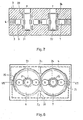
- Fig. 1 the functional diagram of a 4/2-way valve with hydraulic actuation is shown.
- the valve comprises a valve housing 1 with an upper housing part 2 and a lower housing part 3.
- An intermediate plate 4 with an eyeglass-shaped seat 5 for two switching disks 6 and 7 is arranged between the upper and the lower housing part.
- the upper housing part 2, the lower housing part 3 and the intermediate plate 4 are provided with seals, not shown, and connected to one another by screws and centering pins, also not shown.
- the S chaltusionn 6 and 7 are arranged in tight valve housing with clearance. Both discs each have two switching holes 8 and 9, respectively. 10 and 11, which chaltusionn-axially into the S are arranged. Only one or more holes per disk could also be provided be.
- the axial bores 16 and 18 are connected to one another by a horizontal channel A provided in the lower housing part 3 and the axial bores 17 and 19 are connected to one another by a horizontal channel B also provided in the lower housing part 3.
- the vertical bores 16, 17, 18 and 19 extend through the lower and upper housing part, the mirror bores in the upper housing part being blind, but having the same diameter and the same position as the bores opposite them in the lower housing part. These blind holes equalize the pressure.
- the switching disks 6 and 7 each have six axial pressure compensation bores 20 in two parallel rows to the slots 12 and 13, so that in the closed state, ie when the switching bores of the switching disks do not match the vertical bores 16, 17, 18, 19 in the housing communicate, which are connected to each other in the lower and upper part of the housing via a pressure compensation hole.
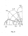
- FIG 5 shows the position of one switching bore in two different, closed positions. In positions between these positions, the switching bore 8, 10 communicates with the bore 16, 18 in the valve housing.
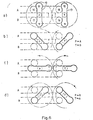
- the switching disks ie. the slots 12 and 13 arranged in them are shown in four different positions.
- positions a and c the inlet and. Return holes P and T are not connected to channels A and B.
- the inlet bore P of the left switching disk is connected to the channel A and the return bore T is connected to the channel B.
- the inlet bore P of the left switching disc is connected to the channel B and the return bore T of the right switching disc is connected to the channel A.
- the holes Z 1 or Z 2 the working medium enters the area of the toothing of the two switching disks 6 and 7, and through the other hole the working medium flows back to a container located outside the valve.
- the speed of the switching discs 6 and 7 depends on the flow rate of the drive medium and can be influenced from the outside. Both switching disks 6 and 7 rotate synchronously as a result of the toothing 14 and 15 attached to their circumference, the switching bores 8, 9, 10 and 11 in the switching disks 6 and 7 the bores 16, 17 located in the upper and lower housing parts 2 and 3, Roam 18 and 19.
- the filled points in the drawing represent any two points on the circumference of the switching disc and illustrate the synchronous rotary movement of the switching discs under the influence of the drive medium.
- the slots 12 and 13 in the switching disks 6 and 7 each connect both switching holes 8 and 9 provided in the disks. 1 0 and 11 permanently with the hole P for the working medium supply, respectively. with the hole T for the working medium return.
- each switching disc 16 and 17 with a hollow bearing pin 21 and. 22 equipped, which transmits the radial forces to the bearing bushes 23 and 24 provided in the valve housing.
- the radial forces can be largely reduced by relief grooves 25 and relief channels 26 in the intermediate plate 4.
- only one switching bore is provided per switching disk, in which case the switching bore with the inlet resp. Return hole in the housing connecting slot in the switching disc can only be formed on one side.
- the channels A and B provided in the lower housing part 3 are connected with lines which lead to a vibration cylinder, where alternately one side of the piston and then the other side of the piston are pressurized.
Landscapes
- Engineering & Computer Science (AREA)
- Chemical & Material Sciences (AREA)
- Analytical Chemistry (AREA)
- Physics & Mathematics (AREA)
- Fluid Mechanics (AREA)
- Mechanical Engineering (AREA)
- General Engineering & Computer Science (AREA)
- Multiple-Way Valves (AREA)
- Fluid-Driven Valves (AREA)
Priority Applications (1)
| Application Number | Priority Date | Filing Date | Title |
|---|---|---|---|
| AT85890104T ATE32624T1 (de) | 1984-05-11 | 1985-05-03 | Wegeventil mit hydraulischer betaetigung. |
Applications Claiming Priority (2)
| Application Number | Priority Date | Filing Date | Title |
|---|---|---|---|
| CH2356/84A CH666091A5 (de) | 1984-05-11 | 1984-05-11 | Drehschieberventil mit hydraulischem drehantrieb. |
| CH2356/84 | 1984-05-11 |
Publications (2)
| Publication Number | Publication Date |
|---|---|
| EP0161237A1 true EP0161237A1 (fr) | 1985-11-13 |
| EP0161237B1 EP0161237B1 (fr) | 1988-02-24 |
Family
ID=4231874
Family Applications (1)
| Application Number | Title | Priority Date | Filing Date |
|---|---|---|---|
| EP85890104A Expired EP0161237B1 (fr) | 1984-05-11 | 1985-05-03 | Distributeur à commande hydraulique |
Country Status (5)
| Country | Link |
|---|---|
| US (1) | US4633903A (fr) |
| EP (1) | EP0161237B1 (fr) |
| AT (1) | ATE32624T1 (fr) |
| CH (1) | CH666091A5 (fr) |
| DE (1) | DE3561671D1 (fr) |
Families Citing this family (3)
| Publication number | Priority date | Publication date | Assignee | Title |
|---|---|---|---|---|
| US5241733A (en) * | 1991-09-10 | 1993-09-07 | Geber Garment Technology, Inc. | Method of making a cloth cutter bristle bed from elongate support members |
| FR2685944B1 (fr) * | 1992-01-08 | 1995-05-19 | Snecma | Valve rotative de distribution de fluide et ensemble de valves en faisant application. |
| WO2022117143A1 (fr) * | 2020-12-01 | 2022-06-09 | Hanon Systems Efp Deutschland Gmbh | Dispositif de régulation d'un débit et de distribution d'un fluide dans un circuit de fluide, et unité de transport dotée dudit dispositif |
Citations (4)
| Publication number | Priority date | Publication date | Assignee | Title |
|---|---|---|---|---|
| US2807141A (en) * | 1953-06-02 | 1957-09-24 | Don S Strader | Pulsator for a hydraulic system |
| US3296874A (en) * | 1964-12-16 | 1967-01-10 | Gen Motors Corp | Vibration generator |
| GB1316261A (en) * | 1969-06-27 | 1973-05-09 | Howard Ltd C A E C | Fluid flow control valves |
| DE2819404A1 (de) * | 1978-05-03 | 1979-11-08 | Wildfang Dieter Kg | Fluessigkeits-impulsgeber |
Family Cites Families (7)
| Publication number | Priority date | Publication date | Assignee | Title |
|---|---|---|---|---|
| GB298935A (en) * | 1927-07-14 | 1928-10-15 | Arthur Treve Holman | Improvements in or relating to fluid-actuated rock-drills and similar tools |
| US2178182A (en) * | 1939-03-31 | 1939-10-31 | Harry F Morgan | Valve structure |
| US2837115A (en) * | 1956-10-09 | 1958-06-03 | Howard S Bancroft | Fluid pressure controlling valve |
| US3499465A (en) * | 1967-02-08 | 1970-03-10 | Maurice Rhodes Zent | Milking machines |
| US3654961A (en) * | 1969-03-14 | 1972-04-11 | Albert Phillips | Rotary percussion drill having a hydraulically actuated percussion device |
| US4373874A (en) * | 1979-07-30 | 1983-02-15 | Albert Phillips | Fluid actuated pump system |
| US4478248A (en) * | 1983-01-20 | 1984-10-23 | Devall Donald L | Rotary valve |
-
1984
- 1984-05-11 CH CH2356/84A patent/CH666091A5/de not_active IP Right Cessation
-
1985
- 1985-05-03 DE DE8585890104T patent/DE3561671D1/de not_active Expired
- 1985-05-03 EP EP85890104A patent/EP0161237B1/fr not_active Expired
- 1985-05-03 AT AT85890104T patent/ATE32624T1/de not_active IP Right Cessation
- 1985-05-10 US US06/732,724 patent/US4633903A/en not_active Expired - Fee Related
Patent Citations (4)
| Publication number | Priority date | Publication date | Assignee | Title |
|---|---|---|---|---|
| US2807141A (en) * | 1953-06-02 | 1957-09-24 | Don S Strader | Pulsator for a hydraulic system |
| US3296874A (en) * | 1964-12-16 | 1967-01-10 | Gen Motors Corp | Vibration generator |
| GB1316261A (en) * | 1969-06-27 | 1973-05-09 | Howard Ltd C A E C | Fluid flow control valves |
| DE2819404A1 (de) * | 1978-05-03 | 1979-11-08 | Wildfang Dieter Kg | Fluessigkeits-impulsgeber |
Also Published As
| Publication number | Publication date |
|---|---|
| CH666091A5 (de) | 1988-06-30 |
| ATE32624T1 (de) | 1988-03-15 |
| DE3561671D1 (en) | 1988-03-31 |
| EP0161237B1 (fr) | 1988-02-24 |
| US4633903A (en) | 1987-01-06 |
Similar Documents
| Publication | Publication Date | Title |
|---|---|---|
| DE1285819B (de) | Mehrfachsteuerventil | |
| DE3727066A1 (de) | Durchbiegungseinstellwalze | |
| DE69907611T2 (de) | Anordnung zur befestigung eines stanzwerkzeuges in einer rotationsstanzmaschine für laminiertes material | |
| WO2018001912A1 (fr) | Partie hydraulique d'une pompe à pistons, en particulier d'une pompe à pistons fonctionnant en tant que pompe de balayage | |
| DE10143878B4 (de) | Linearstellglied | |
| DE10243696B3 (de) | Schwenkmotor | |
| DE202005001556U1 (de) | Matritzenscheibe für Rundlauf-Tablettepresse und Rundlauf-Tablettenpresse | |
| EP1179149A1 (fr) | Dispositif d'etancheite pour un piston soumis a l'action d'un fluide sous pression dans un cylindre de travail | |
| DE2303474C3 (de) | Druckmittel-Verteilerblock | |
| WO2010088982A1 (fr) | Organe hydraulique destiné à réguler la pression de freinage d'un système de freinage de véhicule à régulation électronique de patinage | |
| DE10153784B4 (de) | Modulares Steuersystem für eine Ladevorrichtung mit gezielter Sauggreifersteuerung | |
| DE2023268A1 (de) | iT 13.05.70 | |
| EP0161237A1 (fr) | Distributeur à commande hydraulique | |
| DE60025315T2 (de) | Dichtunganordnung | |
| DE19727719C1 (de) | Flüssigkeitsringpumpe | |
| DE19624393A1 (de) | Fliegend gelagerte Druckwerkzylinder | |
| DE3641383C2 (de) | Kolbenschieberventil | |
| EP0257539A2 (fr) | Vanne hydraulique | |
| EP0966610B1 (fr) | Dispositif haute pression | |
| DE2618048A1 (de) | Axialkolbenpumpe oder -maschine | |
| DE1958200C3 (de) | Hydraulische Steuerventileinrichtung | |
| EP0115474B1 (fr) | Dispositif accessoire pour étaux de machine-outil | |
| DE3910381A1 (de) | Sammelanschlussplatte | |
| CH672659A5 (fr) | ||
| DE19630477A1 (de) | Offenend-Spinnvorrichtung |
Legal Events
| Date | Code | Title | Description |
|---|---|---|---|
| PUAI | Public reference made under article 153(3) epc to a published international application that has entered the european phase |
Free format text: ORIGINAL CODE: 0009012 |
|
| AK | Designated contracting states |
Designated state(s): AT DE FR NL |
|
| 17P | Request for examination filed |
Effective date: 19860321 |
|
| 17Q | First examination report despatched |
Effective date: 19861128 |
|
| GRAA | (expected) grant |
Free format text: ORIGINAL CODE: 0009210 |
|
| AK | Designated contracting states |
Kind code of ref document: B1 Designated state(s): AT DE FR NL |
|
| REF | Corresponds to: |
Ref document number: 32624 Country of ref document: AT Date of ref document: 19880315 Kind code of ref document: T |
|
| REF | Corresponds to: |
Ref document number: 3561671 Country of ref document: DE Date of ref document: 19880331 |
|
| ET | Fr: translation filed | ||
| PLBE | No opposition filed within time limit |
Free format text: ORIGINAL CODE: 0009261 |
|
| STAA | Information on the status of an ep patent application or granted ep patent |
Free format text: STATUS: NO OPPOSITION FILED WITHIN TIME LIMIT |
|
| 26N | No opposition filed | ||
| REG | Reference to a national code |
Ref country code: FR Ref legal event code: TP |
|
| NLS | Nl: assignments of ep-patents |
Owner name: HOERBIGER VENTILWERKE AKTIENGESELLSCHAFT TE WENEN, |
|
| PGFP | Annual fee paid to national office [announced via postgrant information from national office to epo] |
Ref country code: FR Payment date: 19960424 Year of fee payment: 12 |
|
| PGFP | Annual fee paid to national office [announced via postgrant information from national office to epo] |
Ref country code: DE Payment date: 19960426 Year of fee payment: 12 |
|
| PGFP | Annual fee paid to national office [announced via postgrant information from national office to epo] |
Ref country code: AT Payment date: 19960524 Year of fee payment: 12 |
|
| PGFP | Annual fee paid to national office [announced via postgrant information from national office to epo] |
Ref country code: NL Payment date: 19960531 Year of fee payment: 12 |
|
| PG25 | Lapsed in a contracting state [announced via postgrant information from national office to epo] |
Ref country code: AT Effective date: 19970503 |
|
| PG25 | Lapsed in a contracting state [announced via postgrant information from national office to epo] |
Ref country code: NL Effective date: 19971201 |
|
| PG25 | Lapsed in a contracting state [announced via postgrant information from national office to epo] |
Ref country code: FR Free format text: LAPSE BECAUSE OF NON-PAYMENT OF DUE FEES Effective date: 19980130 |
|
| NLV4 | Nl: lapsed or anulled due to non-payment of the annual fee |
Effective date: 19971201 |
|
| PG25 | Lapsed in a contracting state [announced via postgrant information from national office to epo] |
Ref country code: DE Free format text: LAPSE BECAUSE OF NON-PAYMENT OF DUE FEES Effective date: 19980203 |
|
| REG | Reference to a national code |
Ref country code: FR Ref legal event code: ST |