EP0159948A1 - Hitch for, especially, agricultural implements supported by a tractor - Google Patents
Hitch for, especially, agricultural implements supported by a tractor Download PDFInfo
- Publication number
- EP0159948A1 EP0159948A1 EP85400752A EP85400752A EP0159948A1 EP 0159948 A1 EP0159948 A1 EP 0159948A1 EP 85400752 A EP85400752 A EP 85400752A EP 85400752 A EP85400752 A EP 85400752A EP 0159948 A1 EP0159948 A1 EP 0159948A1
- Authority
- EP
- European Patent Office
- Prior art keywords
- tool
- tractor
- points
- lifting system
- attachment
- Prior art date
- Legal status (The legal status is an assumption and is not a legal conclusion. Google has not performed a legal analysis and makes no representation as to the accuracy of the status listed.)
- Granted
Links
Images


Classifications
-
- A—HUMAN NECESSITIES
- A01—AGRICULTURE; FORESTRY; ANIMAL HUSBANDRY; HUNTING; TRAPPING; FISHING
- A01B—SOIL WORKING IN AGRICULTURE OR FORESTRY; PARTS, DETAILS, OR ACCESSORIES OF AGRICULTURAL MACHINES OR IMPLEMENTS, IN GENERAL
- A01B63/00—Lifting or adjusting devices or arrangements for agricultural machines or implements
- A01B63/02—Lifting or adjusting devices or arrangements for agricultural machines or implements for implements mounted on tractors
- A01B63/10—Lifting or adjusting devices or arrangements for agricultural machines or implements for implements mounted on tractors operated by hydraulic or pneumatic means
- A01B63/111—Lifting or adjusting devices or arrangements for agricultural machines or implements for implements mounted on tractors operated by hydraulic or pneumatic means regulating working depth of implements
- A01B63/114—Lifting or adjusting devices or arrangements for agricultural machines or implements for implements mounted on tractors operated by hydraulic or pneumatic means regulating working depth of implements to achieve a constant working depth
-
- A—HUMAN NECESSITIES
- A01—AGRICULTURE; FORESTRY; ANIMAL HUSBANDRY; HUNTING; TRAPPING; FISHING
- A01B—SOIL WORKING IN AGRICULTURE OR FORESTRY; PARTS, DETAILS, OR ACCESSORIES OF AGRICULTURAL MACHINES OR IMPLEMENTS, IN GENERAL
- A01B59/00—Devices specially adapted for connection between animals or tractors and agricultural machines or implements
- A01B59/04—Devices specially adapted for connection between animals or tractors and agricultural machines or implements for machines pulled or pushed by a tractor
- A01B59/042—Devices specially adapted for connection between animals or tractors and agricultural machines or implements for machines pulled or pushed by a tractor having pulling means arranged on the rear part of the tractor
-
- A—HUMAN NECESSITIES
- A01—AGRICULTURE; FORESTRY; ANIMAL HUSBANDRY; HUNTING; TRAPPING; FISHING
- A01B—SOIL WORKING IN AGRICULTURE OR FORESTRY; PARTS, DETAILS, OR ACCESSORIES OF AGRICULTURAL MACHINES OR IMPLEMENTS, IN GENERAL
- A01B59/00—Devices specially adapted for connection between animals or tractors and agricultural machines or implements
- A01B59/06—Devices specially adapted for connection between animals or tractors and agricultural machines or implements for machines mounted on tractors
- A01B59/066—Devices specially adapted for connection between animals or tractors and agricultural machines or implements for machines mounted on tractors of the type comprising at least two lower arms and one upper arm generally arranged in a triangle (e.g. three-point hitches)
- A01B59/068—Devices specially adapted for connection between animals or tractors and agricultural machines or implements for machines mounted on tractors of the type comprising at least two lower arms and one upper arm generally arranged in a triangle (e.g. three-point hitches) the lower arms being lifted or lowered by power actuator means provided externally on the tractor
Definitions
- the invention relates to a coupling device for a particularly agricultural tool, intended to be carried by a tractor, said tool being provided with means for hooking to a lifting system, of the three-point type, of the tractor, the 'assembly being arranged to allow movements of the tool allowing it to remain substantially parallel to the ground, regardless of the tractor.
- Coupling devices of this kind are known, in particular from patent FR 1 284 856. They allow wide implements, in particular implements whose width is greater than that of the tractor, to better follow the soil profile, at implement level, independent of the tractor.
- the object of the invention is, above all, to make coupling devices of the kind defined above such that they respond better than hitherto to the various requirements of practice and in particular such that they no longer have, or to a lesser degree, the drawbacks mentioned above.
- a coupling device according to the invention ensures a good distribution of the loads on the tool, a good transfer of part of these loads to the tractor, and rapid and precise movements of this tool. , to follow the soil profile. More particularly still, it is desired to ensure a transfer of the loads supported by depth control means, to the tractor, in order to improve the traction capacity.
- a coupling device for a tool in particular an agricultural tool, intended to be carried by a tractor, said tool being provided with means for hooking to a lifting system, of the three-point type, of the tractor, the assembly being arranged to allow movements of the tool allowing it to remain substantially parallel to the ground, independently of the tractor, is characterized in that connection means are provided between the lifting system of the tractor and the attachment means of the tool, and that these connection means comprise connecting means allowing the tool to perform tilting movements around at least two axes not parallel to each other but parallel or substantially parallel to the ground, the means for hooking the tool being, of a manner known in itself, rigidly linked to said tool.
- connection means comprise means for controlling the movements of the tool independently of the lifting system of the tractor, these control means being combined with means sensitive to the position of the tool by report to the ground so that the information provided by these sensitive means is used for the actuation of the above control means.
- the above-mentioned sensitive means at the position of the tool with respect to the ground comprise, for each gauge wheel, a force sensor capable of determining the loads carried by the wheel, the information provided by each sensor used for actuating the control means.
- the control means are adapted to intervene so that the load supported by each gauge wheel remains substantially constant and equal to a predetermined value, in particular adjustable, between a minimum threshold and a maximum threshold, the additional load being transferred to the tractor.
- the load values adopted for each gauge wheel are equal.
- the control means may comprise at least two elementary control means capable of developing, each, a control force, intended to be transmitted to the tool, having a component in the longitudinal direction, or direction of advance of the tool , and a component in the transverse direction, at least two means sensitive to the position of the tool relative to the ground being provided and associated respectively with the elementary control means.
- the two elementary control means are advantageously formed by two jacks whose axes are concurrent, the end of these jacks located towards the competition point being connected to a high point of the three-point lifting system of the tractor, while the two other ends of these jacks are connected, respectively, to two different points, spaced from one another in the transverse direction, and offset in the longitudinal direction relative to the above high point, the above two different points being rigidly connected between them and, when the tool is coupled, being rigidly connected to this tool.
- connection means comprise an intermediate support, forming a sort of frame, comprising in the upper part three attachment points rigidly connected together, the two end points in the transverse direction constituting the above two different points to which the means are connected. control, while the third attachment point, generally located midway between the two extreme points, is connected, in particular by an articulated link or the like, to the high point of the attachment means of the tool.
- the support comprises, at its lower part, two other attachment points, on each side, for receiving the two lower attachment points of the tool, this lower part of the support being mounted, in its middle part, on articulation means allowing the support to tilt in at least two non-parallel directions, in particular orthogonal, parallel or substantially parallel to the ground.
- the support can be provided, in the middle of its lower part, with a hinge means with a longitudinal axis, intended to be substantially horizontal while the mean plane of the support is substantially vertical, suitable for cooperating with a hinge means complementary integral with a transverse bar intended to be supported by the two low points of attachment of the three-point lifting system of the tractor, this bar being itself rotatably mounted around its transverse axis.
- connection between the ends of the two jacks situated towards their point of competition, with the high point of the three-point lifting system of the tractor comprises a secondary part, intended to be hung at this high point of the lifting system of the tractor. , and comprising two yokes integral with one another and forming between them an angle corresponding to that of the jacks, said ends of the jacks being hung on these yokes.
- Such a coupling device can be provided either at the rear of the tractor, for a tool located at the rear, or at the front of the tractor, in which case the tool is pushed by the tractor, or both the front and rear of the tractor for a pushed implement and for another pulled implement.
- the invention also relates to the elements of a coupling device as defined above.
- an element of this coupling device is characterized in that it comprises a support forming a sort of frame, intended to be placed between the three-point lifting system of the tractor, and the hooking means of the tool, this support comprising, in the upper part, three attachment points rigidly connected to each other, the two points located at the transverse ends being intended to be connected, by the aforesaid control means, at the high point of the tractor lifting system, while the third point, generally located midway between the two extreme points, is intended to be connected, by an articulated link or the like, to the high point of the means of attachment of the tool, the support comprising, at the bottom, two other attachment points at the transverse ends, similar to the bottom attachment points of the lifting system of the tractor, and suitable for receiving the two bottom attachment points of the tool, this support comprising, in the middle of its lower part, a means of articulation with a longitudinal axis, intended to be substantially horizontal while the support is placed substantially vertically.
- Another element of a coupling device consists of a transverse bar, intended to be supported by the two low points of attachment of the lifting system of the tractor, this bar comprising, in its middle part, a means of longitudinal articulation complementary to that provided on the support, said bar being suitable for being mounted on the low attachment points of the lifting system of the tractor so as to be able to rotate about its axis.
- Another element of a coupling device consists of a secondary part, intended to be hooked to the highest point of the lifting system of the tractor, and comprising two yokes integral with one another and forming a angle corresponding to that of the cylinders of the control means, these cylinders being intended to be attached to each of these yokes, at one of their ends.
- the invention also relates to the assembly of a coupling device and a tool attached to a tractor by this coupling device, this assembly being characterized in that the tool comprises means sensitive to its position by ground report, combined with the above control means so that the information provided by these sensitive means are used for the actuation of the above control means.
- the aforementioned assembly is characterized in that the means sensitive to the position of the tool relative to the ground are constituted by the gauge wheels, respectively comprising a force sensor capable of determining the loads supported by each wheel, connection means being provided between these force sensors and the control means to obtain the desired actuation, in order to transfer the loads supported by the wheels towards the tractor, without altering the ground following by them.
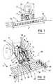
- FIGS. 1 and 2 one can see a coupling device A for a relatively wide agricultural or agricultural tool 1, intended for be carried by a tractor 2.
- the width L of the implement can be much greater than the width 1 of the tractor.
- the tool 1 is provided with means for hooking B to a lifting system C of the three-point type of the tractor 2.
- the coupling device comprises connection means R provided between the lifting system C of the tractor and the means of attachment B of the tool, these connection means R being arranged to allow movements of the tool allowing it to remain substantially parallel to the ground, at the level of the tool.
- the tool can take an inclination relative to the tractor, to follow the profile of the soil.
- connection means R comprise, between the attachment means B and the lifting system C, connection means J allowing the tool 1 to perform tilting movements around at least two axes 24, 25 not parallel to each other but parallel or substantially parallel to the ground T.
- connection means J comprise means of control S of the movements of the tool in an autonomous manner with respect to the lifting system C of the tractor, these control means S being combined with means E sensitive to the position of the tool 1 relative to the ground T, so that the information provided by these sensitive means E is used for the actuation of the above control means S.
- the lifting system C of the conventional tractor is of the three-point type, a high point 3 and two low points 4, 5.
- the high point 3 can be formed by a yoke provided at the end of an arm which can be raised or lowered in a longitudinal or vertical plane.
- Points 4 and 5 are provided at the ends of two longitudinal arms, articulated on the tractor.
- the attachment points 4 and 5 can be of the ball type.
- the attachment means B of the tool 1 comprise, for example, a rigid triangular frame 6 integral with the chassis of the tool 1.
- This frame 6 comprises a lower horizontal side, forming a base, the transverse ends of which 7, 8 could be attached, in the event that the coupling device A according to the invention is not used, directly on points 4 and 5 of the lifting system of the tractor.
- the frame 6, the shape of which is that of an isosceles triangle, has its two equal sides which converge towards the apex 9 provided, for example, with a yoke. Still assuming that the coupling device A of the invention would not be used, this apex 9 would be directly connected by a bar or a rigid rod to the high point 3 of the lifting system of the tractor.
- connection means R comprise an intermediate support 10 also forming a sort of frame, this support comprising in the upper part three attachment points 11, 12, 13 rigidly connected to each other.
- the two points 11, 13 located at the transverse ends are connected to the aforementioned control means S while the third attachment point 12 located midway between the end points 11, 13 is connected by a rod 14, rigid, at the high point 9 attachment means B of the tool.
- the attachment points 11, 12 and 13 can be formed by yokes.
- the support 10 comprises, at its lower part, two other attachment points 15, 16 located at its transverse ends. These attachment points 15 and 16 are made in a manner similar to the conventional attachment points 4 and 5 of the tractor so that the points bottom attachment 7 and 8 of the tool 1 can be received in these attachment points 15 and 16, without any necessary adaptation.
- the support 10 is provided, in the middle of its lower part, with a longitudinal hinge pin 17, that is to say parallel to the direction of advance P, shown diagrammatically by an arrow, of the tool 1.
- L axis 17 is perpendicular to the mean plane of the support 10, this mean plane being intended to be substantially vertical and transverse with respect to said direction of advance P.
- the support 10 is constructed so as to have great rigidity and can be formed by a triangulated structure as visible in FIG. 2. It comprises a horizontal upper rigid bar 18 whose attachment points 11, 12, and 13 are integral and a rigid lower horizontal bar 19, integral with the axis 17 and provided at its ends with attachment points 15 and 16. Diagonal bars respectively connect point 11 to point 15 and one end of axis 17 while two other diagonal bars connect the point 13 to said end of the axis 17 and to the other attachment point 16.
- the four diagonal bars of the support 10 form a kind of capital M as visible in FIG. 2.
- the longitudinal axis 17 is received in a complementary articulation means formed by a bore 20 (fig. 3) provided in a cylinder 21 integral with a transverse bar 22 intended to hang on and to be supported by the two low points hooking 4 and 5 of the lifting system C of the tractor.
- the axis 17 is preferably located below the bar 22 allowing the passage of a power take-off transmission above this axis 17 and between the triangulation of the tool and the connection means.
- the position of the axis 17 is chosen so as not to cause ground clearance problems during work.
- the cylinder 21 is located below the bar 22 and is fixed on this bar for example by gussets such as 23 in particular welded to said bar and to the cylinder.
- the bar 22 is mounted on the attachment points 4 and 5 so that it can rotate around the transverse geometric axis 24, relative to the lifting system C of the tractor.
- the support 10 can also rotate around the longitudinal geometric axis 25 of the cylinder 21 and the axis 17.
- the geometric axes 24 and 25, which are not parallel to each other, are parallel, or substantially parallel, to the ground T.
- the movements of the tool 1, in order to remain parallel to the ground, consist of tilting around these two axes.
- the control means S of the movements of the tool 1 comprise two elementary control means formed respectively by two jacks 26, 27 capable of developing, each, a control force such as F (FIG. 4), intended to be transmitted to the tool 1 and having a component FI in the longitudinal direction, or direction of advance P of the tool, pushed or pulled, and a component Ft in the transverse direction.
- F control force
- the axes of the two jacks 26, 27 are concurrent towards a geometric point 28 (FIG. 4) advantageously located in the center of the yoke constituting the top attachment point 3.
- the two jacks 26, 27 can be arranged so that the plane of their concurrent axes is horizontal when the tractor 2 and the tool 1 move on the same horizontal flat surface, but this characteristic is not essential.
- the two cylinders 26 and 27 could be inclined relative to the horizontal plane.
- each cylinder located towards the competition point 28, is connected to the high point 3 of the lifting system C.
- Each end is equipped with a ball joint suitable for being received between the branches of two respective female yokes 31, 32, integral with one another and forming between them an angle corresponding to that of the jacks.
- the yokes 31, 32 are part of a secondary part 33 which has a male yoke 38 suitable for being received in a female yoke constituting the attachment point 3.
- the connection between the various male and female yokes is ensured by transverse axes such as 34, orthogonal to the forces transmitted between the yokes.
- the jacks 26 and 27 when the tractor and the implement are rolling on a flat horizontal surface are symmetrical to each other with respect to a longitudinal vertical plane passing through the point 28.
- the attachment points 11 and 13 are also symmetrical with respect to this longitudinal plane, and are produced in the form of yokes, as visible in FIG. 4, secured, in particular by welding, to the support 10, and oriented in the inclined direction of the associated jack.
- the rods 26a, 27a of the jacks 26, 27 are provided at their ends with ball joints attached to points 11 and 13.
- the tool 1 has two gauge wheels 35, 36 ( Figure 2) provided on each side of the tool, in the transverse direction. If the tool 1 was located at the rear of the tractor and pulled by it, the gauge wheels 35 and 36 would be at the rear of the tool 1. In the envisaged case of a tool pushed by the tractor and mounted at the front of this tractor, the gauge wheels are located in front of said tool. Part of the load on tool 1, due to the weight and dynamic effects, is exerted on these gauge wheels 35, 36.
- gauge wheels 35, 36 mounted at the end of a longitudinal arm 37, substantially parallel to the direction P , this arm being articulated around a transverse axis 37a schematically represented.
- the wheel 35, 36 can be mounted at the lower end of a vertical rod 37b fixed, in particular in an adjustable manner in the vertical direction, at the end of the arm 37 remote from the axis 37fl.
- Elastic means formed by a block 37c of elastic material, for example elastomer are provided between the arm 37 and a stop 37d secured to the frame of the tool 1 to allow the movement of the arm 37 while limiting it.
- Block 37c in the example considered works in compression.
- the position of this block 37c is advantageously adjustable in the longitudinal direction shown by the double arrow F in FIG. 5. The adjustment of the position of the block 37c makes it possible to adjust the load supported by the wheel 35.
- the means E (see FIGS. 2 and 5) sensitive to the position of the tool 1 relative to the ground T, are advantageously constituted by the gauge wheel 35, 36 comprising a force sensor capable of determining the supported loads by the associated wheel, the information provided by each sensor used to actuate the control means S.
- the force sensor 39 for the wheel 35 (or 40 for the wheel 36) comprises a cam 41 linked in rotation to the arm 37 supporting the wheel and an electrical contact 42 comprising a feeler 43 which presses against the cam 41.
- the probe 43 is pushed against the cam 41 by a spring 44 housed in a housing 45 linked to the chassis of the tool 1; the spring 44 bears at one end against a stop 46.
- the contact 42 in the rest position the contact 42 is open; the electrical contact can be established between the pad 47, (formed for example of two elementary pads spaced from one another carried by the probe 43) and the pads 48a, 48b linked to the housing 45; these pads are suitably insulated compared to neighboring rooms.
- the contact between the pads 47, 48a closes when the load supported by the wheel 35 exceeds the predetermined limit, because the rotation of the cam 41, clockwise according to the representation of FIG. 5, causes the rod 43 to move to the right of the drawing in FIG. 5 until the contact is closed.
- the contact between the pads 47 and 48b closes when the load supported by the wheel 35 becomes too low, which causes movement of the probe 43 in the other direction.
- the three pads 47, 48a, 48b, of the electrical contact are connected by electrical connection conductors 49, 50a, 50b to two control assemblies 51a, 51b for example electromagnets, acting on a distributor 52 of hydraulic fluid under pressure , intended to control the supply of the jack 26 associated with the wheel 35.
- the hydraulic fluid under pressure comes from a source 53 connected by suitable pipes 54 to orifices of the distributor 52.
- the cylinder 26 can be of the single-acting type and a single chamber of this cylinder is connected by a pipe 55 to an orifice of the solenoid valve 52.
- the cylinder 26 works to shorten, that is to say that when the liquid under pressure is admitted into the cylinder chamber, the rod 26a of the latter enters the cylinder.
- the return of the jack, when the pipe 55 is connected to the cover, is provided by the load against which the jack is intended to act, this load causing the rod 26a to exit.
- the assembly is arranged so that when the electrical contacts are open, the solenoid valve 52 is in a closed position and the hydraulic fluid is trapped in the cylinder chamber 26 so that the piston and the piston rod of this cylinder cannot move in translation relative to the cylinder of the cylinder, under the effect of the load.
- the solenoid valve 52 is controlled by the coil 51b so that the chamber of the cylinder 26 is connected to the cover, which causes the piston rod 26a to exit the cylinder of this cylinder and to increase the distance between the points 3 and 11 (figure 4).
- This modification causes an increase in the load on the wheel 35.
- control means S make it possible for each gauge wheel 35, 36 to bear a substantially constant load.
- control means S are adjusted so that the load supported by the wheel 35 is equal to that supported by the wheel 36.
- force sensors than that represented in FIG. 5 can be used.
- the force sensors such as 39, 40 it is possible to detect load variations on the gauge wheels to which correspond relatively small variations in height of the tool relative to the ground T, for example of the order of a centimeter or even of the order of a few millimeters.
- the force sensors such as 39, 40 make it possible to accurately detect the load transferred to the tractor without altering the position relative to the ground.
- the attachment point 3 is put in place of the lifting system C of the tractor, the intermediate piece 33 comprising the yokes 31, 32.
- the bar 22 is then put in place by hooking it to the two low points 4, 5 of the lifting system C of the tractor.
- the ends 29, 30 of the rods secured to the cylinders 26, 27 are hooked to the yokes 31, 32, using pins such as 34.
- the support 10 is then put in place by inserting the pin 17 into the bore 20 supported by bar 22 and by hooking points 11 and 13 of this support 10 to rods 26a, 27a, jacks 26 and 27.
- axis 17 can be blocked, removably, in the longitudinal direction, relative to the bore 20; the support 10 and the bar 22 then form an assembly.
- the tool is then fixed, by its frame 6, to the support 10, the three points 7, 8 and 9 of this frame 6 being attached to points 15, 16 and 12 of said support 10.
- the electrical connection is then made between the sensors 39, 40 of the wheels 35 and 36 of the tool with the control coils such as 51a, 51b of the solenoid valves such as 52 controlling the jacks such as 26, 27.
- the hydraulic connection is made, in particular by flexible pipes, on the one hand between each solenoid valve 52 and the associated jack 26, 27 and, on the other hand, between the source of pressurized liquid 53, in particular formed by the tractor hydraulic unit, and these solenoid valves.
- the operation of the coupling device is as follows.
- the moment of the transverse component Ft relative to the axis 25 causes, according to the representation of FIG. 2, a rotation of the support 10 and therefore a tilting of the tool 1, around this axis 25, in the opposite direction of the clockwise, seen from the rear of the tool 1, so that the load supported by the wheel 35 decreases.
- the device according to the invention makes it possible to positively control the maintenance of the tool 1 parallel to the ground by ensuring substantially constant loads on the gauge wheels 35, 36, these loads being preferably equal.
- the coupling device and its control can be adapted according to the nature of the soil worked by the tool. For example, for a hard floor, the setting of the spring 44 will correspond to a higher value and therefore to a higher load on the wheel 35 which makes it possible to smooth the information collected by the sensors and to eliminate instantaneous variations such as those caused by hard clods of earth, linked to the state of the surface. The load supported by the tractor is then lower, but this is not a problem since the tractor has good grip, because the ground is hard.
- the sensors 39 and 40 are adjusted so that the load supported by the wheels 35 and 36 is relatively weak to increase the grip of the tractor, the problem of smoothing the information provided by the sensors being less acute.
- stops such as 56, 57 (FIGS. 3 and 4) suitable for coming to cooperate with the transverse bar 25, at during rotation about the longitudinal axis 25, to limit the amplitude of this rotation.
- the yoke constituting the point of attachment 12 of the support 10, and to which the connecting rod 14 is hung may have, in its wings, several holes 58, superimposed, three for example in the case of the figure 3, which allows the attachment of said rod 14 to the pair of holes best suited for the tool in question.
- a spherical ball joint located on the bar 19 equidistant from points 15 and 16, and adapted to cooperate with an additional housing carried by a support mounted on the attachment points 4 and 5 of the tractor.
- the support 10 would have freedom in rotation around a plurality of axes parallel to the ground.
- the example described above relates to a tool of the pushed type which tends to sink when the resistance of the soil increases.
- the single acting cylinder while working to shorten, opposes this tendency to sink.
- a double-acting cylinder, or a single-acting cylinder controlled at elongation could be used (the admission of the pressure of the fluid then causes the exit of the cylinder rod).
- connection means J comprise control means S, in particular formed by jacks, tilting movements of the tool.
- the connecting means J would be passive and formed, for example, by telescopic rods.
- the telescopic links would allow tilting movements around the two axes 24, 25, without ensuring load transfer to the tractor; in other words, points 11 and 13 would in some way be free to debate along the straight line passing through these points and point 28.
- the telescopic rods In the raised position of the lifting system C of the tractor, the telescopic rods would take their maximum length and come into abutment stroke to ensure the transmission of forces for lifting the implement carried by the tractor.
Abstract
Description
DISPOSITIF D'ATTELAGE POUR UN OUTIL, NOTAMMENT AGRICOLE, DESTINE A ETRE PORTE PAR UN TRACTEUR, ELEMENTS DE CE DISPOSITIF ET ENSEMBLE COMPRENANT UN TEL DISPOSITIF.HITCHING DEVICE FOR A TOOL, PARTICULARLY AGRICULTURAL, FOR BEING CARRIED BY A TRACTOR, ELEMENTS OF SUCH A DEVICE AND ASSEMBLY COMPRISING SUCH A DEVICE.
L'invention est relative à un dispositif d'attelage pour un outil notamment agricole, destiné à être porté par un tracteur, ledit outil étant muni de moyens d'accrochage à un système de levage, du type à trois points, du tracteur, l'ensemble étant agencé pour autoriser des mouvements de l'outil lui permettant de rester sensiblement parallèle au sol, indépendamment du tracteur.The invention relates to a coupling device for a particularly agricultural tool, intended to be carried by a tractor, said tool being provided with means for hooking to a lifting system, of the three-point type, of the tractor, the 'assembly being arranged to allow movements of the tool allowing it to remain substantially parallel to the ground, regardless of the tractor.
Des dispositifs d'attelage de ce genre sont connus, notamment d'après le brevet FR 1 284 856. Ils permettent aux outils larges, notamment aux outils dont la largeur est plus grande que celle du tracteur, de mieux suivre le profil du sol, au niveau de l'outil, indépendamment du tracteur.Coupling devices of this kind are known, in particular from
Toutefois, la répartition des charges sur l'outil et le transfert des charges de l'outil vers le tracteur ne sont pas toujours assurés dans de bonnes conditions. En outre, la rapidité et la précision avec laquelle les mouvements de l'outil sont effectués demandent à être améliorées.However, the distribution of loads on the implement and the transfer of loads from the implement to the tractor are not always ensured under good conditions. In addition, the speed and precision with which the movements of the tool are carried out need to be improved.
L'invention a pour but, surtout, de rendre les dispositifs d'attelage du genre défini précédemment tels qu'ils répondent mieux que jusqu'à présent aux diverses exigences de la pratique et notamment tels qu'ils ne présentent plus, ou à un degré moindre, les inconvénients rappelés ci-dessus. On souhaite en particulier qu'un dispositif d'attelage conforme à l'invention assure une bonne répartition des charges sur l'outil, un bon transfert d'une partie de ces charges vers le tracteur, et des mouvements rapides et précis de cet outil, pour suivre le profil du sol. Plus particulièrement encore, on souhaite assurer un transfert des charges supportées par des moyens de contrôle de profondeur, vers le tracteur, pour améliorer la capacité de traction.The object of the invention is, above all, to make coupling devices of the kind defined above such that they respond better than hitherto to the various requirements of practice and in particular such that they no longer have, or to a lesser degree, the drawbacks mentioned above. In particular, it is desired that a coupling device according to the invention ensures a good distribution of the loads on the tool, a good transfer of part of these loads to the tractor, and rapid and precise movements of this tool. , to follow the soil profile. More particularly still, it is desired to ensure a transfer of the loads supported by depth control means, to the tractor, in order to improve the traction capacity.
Selon l'invention, un dispositif d'attelage pour un outil, notamment agricole, destiné à être porté par un tracteur, ledit outil étant muni de moyens d'accrochage à un système de levage, du type à trois points, du tracteur , l'ensemble étant agencé pour autoriser des mouvements de l'outil lui permettant de rester sensiblement parallèle au sol, indépendamment du tracteur, est caractérisé par le fait que des moyens de raccordement sont prévus entre le système de levage du tracteur et les moyens d'accrochage de l'outil, et que ces moyens de raccordement comprennent des moyens de liaison permettant à l'outil d'effectuer des mouvements de basculement autour d'au moins deux axes non parallèles entre eux mais parallèles ou sensiblement parallèles au sol, les moyens d'accrochage de l'outil étant, d'une manière connue en elle-même, rigidement liés audit outil.According to the invention, a coupling device for a tool, in particular an agricultural tool, intended to be carried by a tractor, said tool being provided with means for hooking to a lifting system, of the three-point type, of the tractor, the assembly being arranged to allow movements of the tool allowing it to remain substantially parallel to the ground, independently of the tractor, is characterized in that connection means are provided between the lifting system of the tractor and the attachment means of the tool, and that these connection means comprise connecting means allowing the tool to perform tilting movements around at least two axes not parallel to each other but parallel or substantially parallel to the ground, the means for hooking the tool being, of a manner known in itself, rigidly linked to said tool.
De préférence, les moyens de liaison comprennent des moyens de commande des mouvements de l'outil d'une manière autonome par rapport au système de levage du tracteur, ces moyens de commande étant combinés avec des moyens sensibles à la position de l'outil par rapport au sol de telle sorte que les informations fournies par ces moyens sensibles soient utilisées pour l'actionnement des susdits moyens de commande.Preferably, the connection means comprise means for controlling the movements of the tool independently of the lifting system of the tractor, these control means being combined with means sensitive to the position of the tool by report to the ground so that the information provided by these sensitive means is used for the actuation of the above control means.
Avantageusement, dans le cas d'un outil large comportant deux roues de jauge prévues de chaque côté de l'outil, dans le sens transversal, et sur lesquelles s'exerce une partie de la charge générée par l'outil, les susdits moyens sensibles à la position de l'outil par rapport au sol comprennent, pour chaque roue de jauge, un capteur d'effort propre à déterminer les charges portées par la roue, les informations fournies par chaque capteur servant à l'actionnement des moyens de commande. De préférence, les moyens de commande sont propres à intervenir de telle sorte que la charge supportée par chaque roue de jauge reste sensiblement constante et égale à une valeur prédéterminée, notamment réglable, comprise entre un seuil mini et un seuil maxi, la charge supplémentaire étant transférée vers le tracteur. Généralement, les valeurs de charges adoptées pour chaque roue de jauge sont égales.Advantageously, in the case of a wide tool comprising two gauge wheels provided on each side of the tool, in the transverse direction, and on which a part of the load generated by the tool is exerted, the above-mentioned sensitive means at the position of the tool with respect to the ground, comprise, for each gauge wheel, a force sensor capable of determining the loads carried by the wheel, the information provided by each sensor used for actuating the control means. Preferably, the control means are adapted to intervene so that the load supported by each gauge wheel remains substantially constant and equal to a predetermined value, in particular adjustable, between a minimum threshold and a maximum threshold, the additional load being transferred to the tractor. Generally, the load values adopted for each gauge wheel are equal.
Les moyens de commande peuvent comprendre au moins deux moyens de commande élémentaires propres à développer, chacun, une force de commande, destinée à être transmise à l'outil, ayant une composante suivant la direction longitudinale, ou direction d'avance de l'outil, et une composante suivant la direction transversale, au moins deux moyens sensibles à la position de l'outil par rapport au sol étant prévus et associés respectivement aux moyens de commande élémentaires.The control means may comprise at least two elementary control means capable of developing, each, a control force, intended to be transmitted to the tool, having a component in the longitudinal direction, or direction of advance of the tool , and a component in the transverse direction, at least two means sensitive to the position of the tool relative to the ground being provided and associated respectively with the elementary control means.
Les deux moyens élémentaires de commande sont avantageusement formés par deux vérins dont les axes sont concourants, l'extrémité de ces vérins située vers le point de concours étant reliée à un point haut du système de levage à trois points du tracteur, tandis que les deux autres extrémités de ces vérins sont reliées, respectivement, à deux points différents, écartés l'un de l'autre suivant la direction transversale, et décalés suivant la direction longitudinale par rapport au susdit point haut, les susdits deux points différents étant reliés rigidement entre eux et, lorsque l'outil est attelé, étant reliés rigidement à cet outil.The two elementary control means are advantageously formed by two jacks whose axes are concurrent, the end of these jacks located towards the competition point being connected to a high point of the three-point lifting system of the tractor, while the two other ends of these jacks are connected, respectively, to two different points, spaced from one another in the transverse direction, and offset in the longitudinal direction relative to the above high point, the above two different points being rigidly connected between them and, when the tool is coupled, being rigidly connected to this tool.
Avantageusement, les moyens de raccordement comprennent un support intermédiaire, formant une sorte de cadre, comportant en partie haute trois points d'accrochage rigidement reliés entre eux, les deux points extrêmes dans le sens transversal constituant les susdits deux points différents auxquels sont reliés les moyens de commande, tandis que le troisième point d'accrochage, généralement situé à mi-distance des deux points extrêmes, est relié, notamment par une biellette articulée ou analogue, au point haut des moyens d'accrochage de l'outil. Le support comporte, à sa partie basse, deux autres points d'attache, de chaque côté, pour recevoir les deux points d'accrochage bas de l'outil, cette partie basse du support étant montée, dans sa partie médiane, sur des moyens d'articulation autorisant un basculement du support suivant au moins deux directions non parallèles, notamment orthogonales, parallèles ou sensiblement parallèles au sol.Advantageously, the connection means comprise an intermediate support, forming a sort of frame, comprising in the upper part three attachment points rigidly connected together, the two end points in the transverse direction constituting the above two different points to which the means are connected. control, while the third attachment point, generally located midway between the two extreme points, is connected, in particular by an articulated link or the like, to the high point of the attachment means of the tool. The support comprises, at its lower part, two other attachment points, on each side, for receiving the two lower attachment points of the tool, this lower part of the support being mounted, in its middle part, on articulation means allowing the support to tilt in at least two non-parallel directions, in particular orthogonal, parallel or substantially parallel to the ground.
Le support peut être muni, au milieu de sa partie basse, d'un moyen d'articulation à axe longitudinal, destiné à se trouver sensiblement horizontal alors que le plan moyen du support est sensiblement vertical, propre à coopérer avec un moyen d'articulation complémentaire solidaire d'une barre transversale destinée à être supportée par les deux points bas d'accrochage du système de levage à trois points du tracteur, cette barre étant elle-même montée rotative autour de son axe transversal.The support can be provided, in the middle of its lower part, with a hinge means with a longitudinal axis, intended to be substantially horizontal while the mean plane of the support is substantially vertical, suitable for cooperating with a hinge means complementary integral with a transverse bar intended to be supported by the two low points of attachment of the three-point lifting system of the tractor, this bar being itself rotatably mounted around its transverse axis.
Avantageusement, la liaison entre les extrémités des deux vérins situés vers leur point de concours, avec le point haut du système de levage à trois points du tracteur, comprend une pièce secondaire, prévue pour être accrochée à ce point haut du système de levage du tracteur, et comportant deux chapes solidaires l'une de l'autre et formant entre elles un angle correspondant à celui des vérins, lesdites extrémités des vérins étant accrochées sur ces chapes.Advantageously, the connection between the ends of the two jacks situated towards their point of competition, with the high point of the three-point lifting system of the tractor, comprises a secondary part, intended to be hung at this high point of the lifting system of the tractor. , and comprising two yokes integral with one another and forming between them an angle corresponding to that of the jacks, said ends of the jacks being hung on these yokes.
Un tel dispositif d'attelage peut être prévu soit à l'arrière du tracteur, pour un outil situé à l'arrière, soit à l'avant du tracteur, auquel cas l'outil est poussé par le tracteur, soit à la fois à l'avant et à l'arrière du tracteur pour un outil poussé et pour un autre outil tiré.Such a coupling device can be provided either at the rear of the tractor, for a tool located at the rear, or at the front of the tractor, in which case the tool is pushed by the tractor, or both the front and rear of the tractor for a pushed implement and for another pulled implement.
L'invention est également relative aux éléments d'un dispositif d'attelage tel que défini précédemment.The invention also relates to the elements of a coupling device as defined above.
En particulier, un élément de ce dispositif d'attelage est caractérisé par le fait qu'il comprend un support formant une sorte de cadre, destiné à être placé entre le système de levage à trois points du tracteur, et les moyens d'accrochage de l'outil, ce support comprenant, en partie haute, trois points d'accrochage rigidement reliés l'un à l'autre, les deux points situés aux extrémités transversales étant destinés à être reliés, par les susdits moyens de commande, au point haut du système de levage du tracteur, tandis que le troisième point, généralement situé à mi-distance des deux points extrêmes, est destiné à être relié, par une biellette articulée ou analogue, au point haut des moyens d'accrochage de l'outil, le support comportant, en partie basse, deux autres points d'attache aux extrémités transversales, semblables aux points d'attache bas du système de levage du tracteur, et propres à recevoir les deux points d'accrochage bas de l'outil, ce support comportant, au milieu de sa partie basse, un moyen d'articulation à axe longitudinal, destiné à se trouver sensiblement horizontal alors que le support est placé sensiblement verticalement.In particular, an element of this coupling device is characterized in that it comprises a support forming a sort of frame, intended to be placed between the three-point lifting system of the tractor, and the hooking means of the tool, this support comprising, in the upper part, three attachment points rigidly connected to each other, the two points located at the transverse ends being intended to be connected, by the aforesaid control means, at the high point of the tractor lifting system, while the third point, generally located midway between the two extreme points, is intended to be connected, by an articulated link or the like, to the high point of the means of attachment of the tool, the support comprising, at the bottom, two other attachment points at the transverse ends, similar to the bottom attachment points of the lifting system of the tractor, and suitable for receiving the two bottom attachment points of the tool, this support comprising, in the middle of its lower part, a means of articulation with a longitudinal axis, intended to be substantially horizontal while the support is placed substantially vertically.
Un autre élément d'un dispositif d'attelage conforme à l'invention est constitué par une barre transversale, destinée à être supportée par les deux points bas d'accrochage du système de levage du tracteur, cette barre comportant, dans sa partie médiane, un moyen d'articulation longitudinal complémentaire de celui prévu sur le support, ladite barre étant propre à être montée sur les points bas d'accrochage du système de levage du tracteur de manière à pouvoir tourner autour de son axe.Another element of a coupling device according to the invention consists of a transverse bar, intended to be supported by the two low points of attachment of the lifting system of the tractor, this bar comprising, in its middle part, a means of longitudinal articulation complementary to that provided on the support, said bar being suitable for being mounted on the low attachment points of the lifting system of the tractor so as to be able to rotate about its axis.
Un autre élément d'un dispositif d'attelage selon l'invention est constitué par une pièce secondaire, prévue pour être accrochée au point haut du système de levage du tracteur, et comportant deux chapes solidaires l'une de l'autre et formant un angle correspondant à celui des vérins des moyens de commande, ces vérins étant destinés à être accrochés à chacune de ces chapes, à une de leurs extrémités.Another element of a coupling device according to the invention consists of a secondary part, intended to be hooked to the highest point of the lifting system of the tractor, and comprising two yokes integral with one another and forming a angle corresponding to that of the cylinders of the control means, these cylinders being intended to be attached to each of these yokes, at one of their ends.
L'invention concerne également l'ensemble d'un dispositif d'attelage et d'un outil accroché à un tracteur par ce dispositif d'attelage, cet ensemble étant caractérisé par le fait que l'outil comporte des moyens sensibles à sa position par rapport au sol, combinés avec les susdits moyens de commande de telle sorte que les informations fournies par ces moyens sensibles soient utilisées pour l'actionnement des susdits moyens de commande.The invention also relates to the assembly of a coupling device and a tool attached to a tractor by this coupling device, this assembly being characterized in that the tool comprises means sensitive to its position by ground report, combined with the above control means so that the information provided by these sensitive means are used for the actuation of the above control means.
Dans le cas d'un outil large muni de deux roues de jauge prévues de chaque côté transversal de l'outil, le susdit ensemble est caractérisé par le fait que les moyens sensibles à la position de l'outil par rapport au sol sont constitués par les roues de jauge, comprenant respectivement un capteur d'effort propre à déterminer les charges supportées par chaque roue, des moyens de liaison étant prévus entre ces capteurs d'effort et les moyens de commande pour obtenir l'actionnement souhaité, afin de transférer les charges supportées par les roues vers le tracteur, sans altérer le suivi du sol par celles-ci.In the case of a wide tool provided with two gauge wheels provided on each transverse side of the tool, the aforementioned assembly is characterized in that the means sensitive to the position of the tool relative to the ground are constituted by the gauge wheels, respectively comprising a force sensor capable of determining the loads supported by each wheel, connection means being provided between these force sensors and the control means to obtain the desired actuation, in order to transfer the loads supported by the wheels towards the tractor, without altering the ground following by them.
L'invention consiste, mises à part les dispositions exposées ci-dessus, en certaines autres dispositions dont il sera plus explicitement question ci-après à propos d'un mode de réalisation particulier décrit avec référence aux dessins ci-annexés, mais qui n'est nullement limitatif.
- La figure 1, de ces dessins, est un schéma d'ensemble d'un tracteur, équipé d'un outil large, poussé, vu de l'avant, pour illustrer le mouvement de l'outil par rapport au tracteur.
- La figure 2 est un schéma, en perspective, d'un dispositif d'attelage conforme à l'invention, monté entre le système de levage du tracteur et les moyens d'accrochage de l'outil.
- La figure 3 est une vue de côté du dispositif d'attelage selon l'invention.
- La figure 4 est une vue de dessus par rapport à la figure 3.
- La figure 5, enfin, est un schéma illustrant une réalisation des moyens sensibles à la charge supportée par une roue de jauge de l'outil.
- Figure 1 of these drawings is an overall diagram of a tractor, equipped with a wide tool, pushed, seen from the front, to illustrate the movement of the tool relative to the tractor.
- Figure 2 is a diagram, in perspective, of a coupling device according to the invention, mounted between the tractor lifting system and the attachment means of the tool.
- Figure 3 is a side view of the coupling device according to the invention.
- FIG. 4 is a top view with respect to FIG. 3.
- FIG. 5, finally, is a diagram illustrating an embodiment of the means sensitive to the load supported by a gauge wheel of the tool.
En se reportant aux dessins, notamment aux figures 1 et 2, on peut voir un dispositif d'attelage A pour un outil agricole ou aratoire 1 relativement large, destiné à être porté par un tracteur 2. La largeur L de l'outil peut être nettement supérieure à la largeur 1 du tracteur. Comme exemple d'outil 1, on peut indiquer les chisels, les effeuilleuses, les arracheuses.Referring to the drawings, in particular to FIGS. 1 and 2, one can see a coupling device A for a relatively wide agricultural or
L'outil 1 est muni de moyens d'accrochage B à un système de levage C du type à trois points du tracteur 2. Le dispositif d'attelage comporte des moyens de raccordement R prévus entre le système de levage C du tracteur et les moyens d'accrochage B de l'outil, ces moyens de raccordement R étant agencés pour autoriser des mouvements de l'outil lui permettant de rester sensiblement parallèle au sol, au niveau de l'outil.The
Ainsi, comme représenté sur la figure 1, si la configuration du sol au niveau de l'outil est différente de celle au niveau du tracteur, l'outil peut prendre une inclinaison par rapport au tracteur, pour suivre le profil du sol.Thus, as shown in FIG. 1, if the configuration of the ground at the level of the tool is different from that at the level of the tractor, the tool can take an inclination relative to the tractor, to follow the profile of the soil.
Les moyens de raccordement R comprennent, entre les moyens d'accrochage B et le système de levage C, des moyens de liaison J permettant à l'outil 1 d'effectuer des mouvements de basculement autour d'au moins deux axes 24, 25 non parallèles entre eux mais parallèles ou sensiblement parallèles au sol T.The connection means R comprise, between the attachment means B and the lifting system C, connection means J allowing the
Avantageusement, les moyens de liaison J comprennent des moyens de commande S des mouvements de l'outil d'une manière autonome par rapport au système de levage C du tracteur, ces moyens de commande S étant combinés avec des moyens E sensibles à la position de l'outil 1 par rapport au sol T, de telle sorte que les informations fournies par ces moyens sensibles E soient utilisées pour l'actionnement des susdits moyens de commande S.Advantageously, the connection means J comprise means of control S of the movements of the tool in an autonomous manner with respect to the lifting system C of the tractor, these control means S being combined with means E sensitive to the position of the
Le système de levage C du tracteur classique est du type à trois points, un point haut 3 et deux points bas 4, 5. Le point haut 3 peut être formé par une chape prévue à l'extrémité d'un bras qui peut être relevé ou abaissé dans un plan longitudinal ou vertical. Les points 4 et 5 sont prévus aux extrémités de deux bras longitudinaux, articulés sur le tracteur. Les points d'accrochage 4 et 5 peuvent être du type à rotule.The lifting system C of the conventional tractor is of the three-point type, a
Les moyens d'accrochage B de l'outil 1 comprennent, par exemple, un cadre triangulaire rigide 6 solidaire du châssis de l'outil 1. Ce cadre 6 comprend un côté horizontal inférieur, formant base, dont les extrémités transversales 7, 8 pourraient être accrochées, pour le cas où le dispositif d'attelage A conforme à l'invention ne serait pas utilisé, directement sur les points 4 et 5 du système de levage du tracteur. Le cadre 6, dont la forme est celle d'un triangle isocèle, a ses deux côtés égaux qui convergent vers le sommet 9 muni, par exemple, d'une chape. Toujours dans l'hypothèse où le dispositif d'attelage A de l'invention ne serait pas utilisé, ce sommet 9 serait directement relié par une barre ou une biellette rigide au point haut 3 du système de levage du tracteur.The attachment means B of the
On comprend que tous les mouvements transmis au cadre 6, lié rigidement à l'outil 1, sont transmis à cet outil.It is understood that all the movements transmitted to the
Les moyens de raccordement R, selon l'invention, comprennent un support intermédiaire 10 formant également une sorte de cadre, ce support comportant en partie haute trois points d'accrochage 11, 12, 13 rigidement liés l'un à l'autre. Les deux points 11, 13 situés aux extrémités transversales sont reliés aux susdits moyens de commande S tandis que le troisième point d'accrochage 12 situé à mi-distance des points extrêmes 11, 13 est relié par une biellette 14, rigide, au point haut 9 des moyens d'accrochage B de l'outil. Les points d'accrochage 11, 12 et 13 peuvent être formés par des chapes.The connection means R, according to the invention, comprise an
Le support 10 comporte, à sa partie basse, deux autres points d'attache 15, 16 situés à ses extrémités transversales. Ces points d'attache 15 et 16 sont réalisés d'une manière semblable aux points d'attache 4 et 5 classiques du tracteur de telle sorte que les points d'accrochage bas 7 et 8 de l'outil 1 puissent être reçus dans ces points d'attache 15 et 16, sans aucune adaptation nécessaire.The
Le support 10 est muni, au milieu de sa partie inférieure, d'un axe d'articulation 17 longitudinal c'est-à-dire parallèle à la direction d'avance P, schématisée par une flèche, de l'outil 1. L'axe 17 est perpendiculaire au plan moyen du support 10, ce plan moyen étant destiné à être sensiblement vertical et transversal par rapport à ladite direction d'avance P.The
Le support 10 est construit de manière à présenter une grande rigidité et peut être formé par une structure triangulée comme visible sur la figure 2. Il comprend une barre rigide supérieure horizontale 18 dont les points d'attache 11, 12, et 13 sont solidaires et une barre horizontale inférieure 19 rigide, solidaire de l'axe 17 et munie à ses extrémités des points d'attache 15 et 16. Des barres diagonales relient respectivement le point 11 au point 15 et à une extrémité de l'axe 17 tandis que deux autres barres diagonales relient le point 13 à ladite extrémité de l'axe 17 et à l'autre point d'accrochage 16. Les quatre barres diagonales du support 10 forment une sorte de M majuscule comme visible sur la figure 2.The
L'axe longitudinal 17 est reçu dans un moyen d'articulation complémentaire formé par un alésage 20 (fig. 3) prévu dans un cylindre 21 solidaire d'une barre transversale 22 destinée à s'accrocher et à être supportée par les deux points bas d'accrochage 4 et 5 du système de levage C du tracteur. L'axe 17 est situé de préférence au-dessous de la barre 22 permettant le passage d'une transmission de prise de force au-dessus de cet axe 17 et entre la triangulation de l'outil et des moyens de raccordement. La position de l'axe 17 est choisie de manière à ne pas entraîner de problème de garde au sol pendant le travail. Comme visible sur la figure 3, le cylindre 21 est situé au-dessous de la barre 22 et est fixé sur cette barre par exemple par des goussets tels que 23 notamment soudés sur ladite barre et sur le cylindre. La barre 22 est montée sur les points d'accrochage 4 et 5 de telle sorte qu'elle puisse tourner autour de l'axe géométrique transversal 24, par rapport au système de levage C du tracteur.The
Le support 10 peut en outre tourner autour de l'axe géométrique longitudinal 25 du cylindre 21 et de l'axe 17.The
Les axes géométriques 24 et 25,non parallèles entre eux, sont parallèles, ou sensiblement parallèles, au sol T. Les mouvements de l'outil 1, pour rester parallèle au sol, se composent de basculements autour de ces deux axes.The
Les moyens de commande S des mouvements de l'outil 1 comprennent deux moyens de commande élémentaires formés respectivement par deux vérins 26, 27 propres à développer, chacun, une force de commande telle que F (figure 4), destinée à être transmise à l'outil 1 et ayant une composante FI suivant la direction longitudinale, ou direction d'avance P de l'outil, poussé ou tiré, et une composante Ft suivant la direction transversale.The control means S of the movements of the
Les axes des deux vérins 26, 27 sont concourants vers un point géométrique 28 (figure 4) avantageusement situé au centre de la chape constituant le point d'accrochage haut 3.The axes of the two
Les deux vérins 26, 27 peuvent être disposés de telle sorte que le plan de leurs axes concourants soit horizontal lorsque le tracteur 2 et l'outil 1 se déplacent sur une même surface plane horizontale mais cette caractéristique n'est pas indispensable. Les deux vérins 26 et 27 pourraient être inclinés par rapport au plan horizontal.The two
L'extrémité de chaque vérin, située vers le point de concours 28, est reliée au point haut 3 du système de levage C. Cette extrémité, pour chaque vérin, peut être formée par l'extrémité 29, 30 d'une vis réglable autorisant l'ajustement de la longueur mini ou maxi du moyen de commande. Chaque extrémité est équipée d'une rotule propre à être reçue entre les branches de deux chapes femelles respectives 31, 32, solidaires l'une de l'autre et formant entre elles un angle correspondant à celui des vérins. Les chapes 31, 32 font partie d'une pièce secondaire 33 qui comporte une chape mâle 38 propre à être reçue dans une chape femelle constituant le point d'accrochage 3. La liaison entre les diverses chapes mâles et femelles est assurée par des axes transversaux tels que 34, orthogonaux aux efforts transmis entre les chapes.The end of each cylinder, located towards the
De préférence, les vérins 26 et 27 lorsque le tracteur et l'outil roulent sur une surface plane horizontale, sont symétriques l'un de l'autre par rapport à un plan vertical longitudinal passant par le point 28. Les points d'attache 11 et 13 sont également symétriques par rapport à ce plan longitudinal, et sont réalisés sous la forme de chapes, comme visible sur la figure 4, solidaires, notamment par soudure, du support 10, et orientée s suivant la direction inclinée du vérin associé. Les tiges 26a, 27a des vérins 26, 27 sont munies à leurs extrémités de rotules accrochées aux points 11 et 13.Preferably, the
L'outil 1 comporte deux roues de jauge 35, 36 (figure 2) prévues de chaque côté de l'outil, dans le sens transversal. Si l' outil 1 était situé à l'arrière du tracteur et tiré par celui-ci, les roues de jauge 35 et 36 se trouveraient à l'arrière de l'outil 1. Dans le cas envisagé d'un outil poussé par le tracteur et monté à l'avant de ce tracteur, les roues de jauge se trouvent en avant dudit outil. Une partie de la charge de l'outil 1, due au poids et aux effets dynamiques, s'exerce sur ces roues de jauge 35, 36.The
Sur les schémas des figures 2 et 5, on a représenté des roues de jauge 35, 36 montées à l'extrémité d'un bras 37 longitudinal, sensiblement parallèle à la direction P,, ce bras étant articulé autour d'un axe transversal 37a schématiquement représenté. La roue 35, 36, peut être montée à l'extrémité inférieure d'une tige 37b verticale fixée, notamment de manière réglable suivant le sens vertical, à l'extrémité du bras 37 éloignée de l'axe 37fl. Des moyens élastiques formés par un bloc 37c de matière élastique, par exemple élastomère, sont prévus entre le bras 37 et une butée 37d solidaire du bâti de l'outil 1 pour autoriser le débattement du bras 37 tout en le limitant. Le bloc 37c dans l'exemple considéré travaille en compression. La position de ce bloc 37c est avantageusement réglable suivant la direction longitudinale matérialisée par la double flèche F sur la figure 5. Le réglage de la position du bloc 37c permet de régler la charge supportée par la roue 35.In the diagrams of Figures 2 and 5, there are shown
Les moyens E (voir figures 2 et 5) sensibles à la position de l'outil 1 par rapport au sol T, sont constitués, avantageusement, par la roue de jauge 35, 36 comprenant un capteur d'effort propre à déterminer les charges supportées par la roue associée, les informations fournies par chaque capteur servant à l'actionnement des moyens de commande S.The means E (see FIGS. 2 and 5) sensitive to the position of the
Dans l'exemple représenté sur la figure 5, le capteur d'effort 39 pour la roue 35 (ou 40 pour la roue 36) comprend une came 41 liée en rotation au bras 37 supportant la roue et un contact électrique 42 comprenant un palpeur 43 qui appuie contre la came 41.In the example shown in FIG. 5, the
Le palpeur 43 est poussé contre la came 41 par un ressort 44 logé dans un boîtier 45 lié au châssis de l'outil 1; le ressort 44 est en appui à une extrémité contre une butée 46. Dans l'exemple représenté sur la figure 5, en position de repos le contact 42 est ouvert ; le contact électrique peut s'établir entre la pastille 47, (formée par exemple de deux pastilles élémentaires écartées l'une de l'autre portées par le palpeur 43) et les pastilles 48a, 48b liées au boîtier 45;ces pastilles sont convenablement isolées par rapport aux pièces voisines. Le contact entre les pastilles 47, 48a se ferme lorsque la charge supportée par la roue 35 dépasse la limite prédéterminée, car la rotation de la came 41, dans le sens des aiguilles d'une montre selon la représentation de la figure 5, provoque le déplacement de la tige 43 vers la droite du dessin de la figure 5 jusqu'à la fermeture du contact. Le contact entre les pastilles 47 et 48b se ferme lorsque la charge supportée par la roue 35 devient trop faible, ce qui provoque un mouvement du palpeur 43 dans l'autre sens.The
Les trois pastilles 47, 48a, 48b, du contact électrique sont reliées par des conducteurs de liaison électrique 49, 50a, 50b à deux ensembles de commande 51a, 51b par exemple des électro-aimants, agissant sur un distributeur 52 de fluide hydraulique sous pression, destiné à contrôler l'alimentation du vérin 26 associé à la roue 35.The three
Une installation semblable de commande est prévue pour l'autre roue 36 et le vérin 27 associé.A similar control installation is provided for the
Le fluide hydraulique sous pression provient d'une source 53 reliée par des canalisations appropriées 54 à des orifices du distributeur 52.The hydraulic fluid under pressure comes from a
Le vérin 26 peut être du type à simple effet et une seule chambre de ce vérin est reliée par une canalisation 55 à un orifice de l'électrodistributeur 52. Le vérin 26 travaille au raccourcissement, c'est-à-dire que lorsque le liquide sous pression est admis dans la chambre du vérin, la tige 26a de ce dernier rentre dans le cylindre. Le rappel du vérin, lorsque la canalisation 55 est reliée à la bâche, est assuré par la charge à l'encontre de laquelle le vérin est destiné à agir, cette charge provoquant la sortie de la tige 26a.The
L'ensemble est agencé de telle sorte que lorsque les contacts électriques sont ouverts, l'électrodistributeur 52 est dans une position de fermeture et le fluide hydraulique est emprisonné dans la chambre du vérin 26 de telle sorte que le piston et la tige de piston de ce vérin ne peuvent se déplacer en translation par rapport au cylindre du vérin, sous l'effet de la charge.The assembly is arranged so that when the electrical contacts are open, the
Si le contact entre la pastille 47, et la pastille 48b vient à se fermer, c'est-à-dire si la came 41 tourne dans le sens des aiguilles d'une montre d'un angle suffisant pour provoquer cette fermeture, ce qui correspond à une diminution de la charge supportée par la roue 35, l'électrodistributeur 52 est commandé par la bobine 51b de telle sorte que la chambre du vérin 26 soit reliée à la bâche ce qui provoque une sortie de la tige de piston 26a du cylindre de ce vérin et une augmentation de la distance entre les points 3 et 11 (figure 4). Cette modification provoque une augmentation de la charge sur la roue 35. Lorsque cette augmentation est suffisante, le contact entre les pastilles 47 et 48b s'ouvre et le distributeur 52 revient à sa position fermée.If the contact between the
Si, par suite d'une augmentation de la charge sur la roue 35, la came 41 tourne dans le sens des aiguilles d'une montre, le contact entre les pastilles 47 et 48a va se fermer et l'électrodistributeur 52 va être commandé par la bobine 51a et se déplacer dans le sens qui provoque l'admission du liquide sous pression dans la chambre du vérin 26.11 en résulte que la tige de ce vérin va rentrer dans le cylindre et la distance entre les points 3 et 11 (figure 4) va diminuer, ce qui provoque une diminution de la charge sur la roue 35 jusqu'à ce que la valeur prédéterminée soit obtenue, et un transfert du surplus de charge de l'outil vers le tracteur.If, as a result of an increase in the load on the
Ainsi, les moyens de commande S permettent de faire supporter par chaque roue de jauge 35, 36 une charge sensiblement constante. De préférence, on règle les moyens de commande S de telle sorte que la charge supportée par la roue 35 soit égale à celle supportée par la roue 36.Thus, the control means S make it possible for each
Il est clair que d'autres types de capteurs d"effort que celui représenté sur la figure 5 peuvent être utilisés. On pourrait prévoir des jauges de contrainte montées directement sur le bras ou sur le montant supportant les roues de jauge 35, 36. Il convient de noter qu'avec les capteurs d'effort tels que 39, 40 on peut détecter des variations de charge sur les roues de jauge auxquelles correspondent des variations de hauteur de l'outil par rapport au sol T, relativement faibles, par exemple de l'ordre du centimètre ou même de l'ordre de quelques millimètres. Ainsi, les capteurs d'effort tels que 39, 40 permettent de détecter avec précision la charge transférée vers le tracteur sans altérer la position par rapport au sol.It is clear that other types of force sensors than that represented in FIG. 5 can be used. One could provide strain gauges mounted directly on the arm or on the upright supporting the
Ceci étant, la mise en oeuvre et le fonctionnement du dispositif d'attelage conforme à l'invention sont les suivants .That said, the implementation and operation of the coupling device according to the invention are as follows.
L'accrochage de l'outil 1 sur le tracteur 2 résulte immédiatement des explications précédentes.The attachment of the
Disposant d'un tracteur 2 classique et de l'outil 1 muni de son cadre 6 d'accrochage et du dispositif d'attelage A de l'invention, on met tout d'abord en place, sur le point haut 3 d'accrochage du système de levage C du tracteur, la pièce intermédiaire 33 comportant les chapes 31, 32. On met ensuite en place la barre 22 en l'accrochant aux deux points bas 4, 5 du système de levage C du tracteur. On accroche les extrémités 29, 30 des tiges solidaires des fonds de vérins 26, 27 aux chapes 31, 32, à l'aide d'axes tels que 34. On met ensuite en place le support 10 en introduisant l'axe 17 dans l'alésage 20 supporté par la barre 22 et en accro chant les points 11 et 13 de ce support 10 aux tiges 26a, 27a, des vérins 26 et 27. Il est à noter que selon une variante, l'axe 17 peut être bloqué, de manière démontable, suivant la direction longitudinale, par rapport à l'alésage 20 ; le support 10 et la barre 22 forment alors un ensemble.With a
L'outil est ensuite fixé, par son cadre 6, sur le support 10, les trois points 7, 8 et 9 de ce cadre 6 étant accrochés aux points 15, 16 et 12 dudit support 10.The tool is then fixed, by its
On effectue ensuite la liaison électrique entre les capteurs 39, 40 des roues 35 et 36 de l'outil avec les bobines de commande telles que 51a, 51b des électrodistributeurs tels que 52 commandant les vérins tels que 26, 27. On réalise enfin la liaison hydraulique, notamment par des canalisations flexibles, d'une part entre chaque électro-distributeur 52 et le vérin associé 26, 27 et, d'autre part, entre la source de liquide sous pression 53, notamment formée par la centrale hydraulique du tracteur, et ces électrodistributeurs.The electrical connection is then made between the
On a supposé que l'outil 1 était équipé, au préalable, des capteurs 39, 40 pour chaque roue de jauge 35, 36. Il est clair que l'on peut prévoir des capteurs 39, 40 rapidement adaptables sur les montants ou supports de roues 35 pour permettre l'utilisation d'un outil 1 non équipé de tels capteurs.It was assumed that the
Le fonctionnement du dispositif d'attelage est le suivant.The operation of the coupling device is as follows.
On suppose, par exemple, qu'au cours du travail de l'outil 1 poussé (ou tiré) par le tracteur 2, la charge supportée par la roue 35 dépasse la valeur limite établie par le capteur 39. Dans ces conditions, comme expliqué précédemment avec référence à la figure 5, l'électro-distributeur 52 va être actionné de telle sorte que la chambre du vérin 26 soit reliée au conduit 54 d'arrivée de fluide sous pression et la distance entre les points 3 et 13 (figure 2) va diminuer. Cela provoque un basculement de l'outil tel que la charge supportée par la roue de jauge associée est réduite.It is assumed, for example, that during the work of the
En effet, en raison de l'inclinaison de l'axe du vérin 26 par rapport à la direction longitudinale et à la direction transversale (figure 4) la force exercée par le vérin 26 fait apparaître une composante Fl et une composante Ft.Indeed, due to the inclination of the axis of the
Le moment de la composante transversale Ft par rapport à l'axe 25 provoque, selon la représentation de la figure 2, une rotation du support 10 et donc un basculement de l'outil 1, autour de cet axe 25, dans le sens contraire des aiguilles d'une montre, vu de l'arrière de l'outil 1, de telle sorte que la charge supportée par la roue 35 diminue.The moment of the transverse component Ft relative to the
Le moment de la composante longitudinale Fl par rapport à l'axe 24 de la barre transversale 22 provoque un basculement du support 10 autour de cet axe 24 de telle sorte que le point 11 se rapproche du point 3 et du tracteur 2. Ce mouvement, transmis au cadre 6 et à l'outil 1 soulage également la roue 35. On comprend que le système agit de telle sorte que la charge sur la roue 35 soit maintenue à la valeur prédéterminée.The moment of the longitudinal component F1 with respect to the
Dans le cas où la charge supportée par la roue 35 deviendrait trop faible, des mouvements inverses seraient commandés par le vérin 26 pour rétablir la charge à la valeur souhaitée.In the event that the load supported by the
Il en est de même pour la roue 36.The same is true for
Ainsi, le dispositif conforme à l'invention permet de commander positivement le maintien de l'outil 1 parallèle au sol en assurant des charges sensiblement constantes sur les roues de jauge 35, 36, ces charges étant de préférence égales. On pourrait, si on le souhaitait, annuler pratiquement la charge supportée par les roues 35, 36 en réglant les capteurs 39 et 40 à cet effet ; dans ce cas, la totalité du poids de l'outil serait supportée par le tracteur.Thus, the device according to the invention makes it possible to positively control the maintenance of the
En tarant les capteurs 39 et 40, notamment en tarant le ressort 44, on peut adapter le dispositif d'attelage et sa commande en fonction de la nature du sol travaillé par l'outil. Par exemple, pour un sol dur, le tarage du ressort 44 correspondra à une valeur plus élevée et donc à une charge sur la roue 35 plus importante ce qui permet de lisser les informations recueillies par les capteurs et d'écarter des variations instantanées telles que celles provoquées par des mottes dures de terre, liées à l'état de la surface. La charge supportée par le tracteur est alors moins importante, mais cela n'est pas gênant car le tracteur a une bonne adhérence, du fait que le sol est dur.By taring the
Dans le cas d'un sol humide, on règle les capteurs 39 et 40 de telle sorte que la charge supportée par les roues 35 et 36 soit relativement faible pour augmenter l'adhérence du tracteur, le problème du lissage des informations fournies par les capteurs étant moins aigu.In the case of wet soil, the
Il est noter que l'on peut prévoir, sur le support 10, de part et d'autre de sa région médiane, des butées telles que 56, 57 (figures 3 et 4) propres à venir coopérer avec la barre transversale 25, au cours de la rotation autour de l'axe longitudinal 25, pour limiter l'amplitude de cette rotation.It should be noted that it is possible to provide, on the
Comme visible sur la figure 3, la chape constituant le point d'attache 12 du support 10, et à laquelle est accrochée la biellette 14 peut comporter, dans ses ailes, plusieurs trous 58, superposés, trois par exemple dans le cas de la figure 3, ce qui permet l'accrochage de ladite biellette 14 à la paire de trous la mieux adaptée pour l'outil considéré.As can be seen in FIG. 3, the yoke constituting the point of
On peut remarquer également qu'au lieu de prévoir une possibilité de rotation du support 10 autour de deux axes 24, 25 ayant des directions différentes, notamment orthogonales, et parallèles ou sensiblement parallèles au sol, on pourrait prévoir une articulation à rotule sphérique située sur la barre 19 à égale distance des point 15 et 16, et propre à coopérer avec un logement complémentaire porté par un support monté sur les points d'accrochage 4 et 5 du tracteur. Dans ce cas, le support 10 aurait une liberté en rotation autour d'une pluralité d'axes parallèles au sol.It may also be noted that instead of providing a possibility of rotation of the
Naturellement, au lieu de prévoir un axe 17 sur le support 10 et un alésage 21 sur la barre 22, on pourrait prévoir le montage inverse c'est-à-dire, l'alésage sur le support 10 et l'axe sur la barre 22.Naturally, instead of providing an
L'exemple décrit précédemment concerne un outil du type poussé qui a tendance à s'enfoncer lorsque la résistance du sol augmente. Le vérin simple effet, en travaillant au raccourcissement, s'oppose à cette tendance à l'enfoncement.The example described above relates to a tool of the pushed type which tends to sink when the resistance of the soil increases. The single acting cylinder, while working to shorten, opposes this tendency to sink.
Dans le cas d'un outil qui aurait tendance à se soulever lorsque la résistance du sol augmente, par exemple dans le cas d'un outil du type chisel tiré (et non plus poussé) par le tracteur, on pourrait utiliser un vérin double effet, ou un vérin simple effet piloté à l'allongement (l'admission de la pression du fluide provoque alors la sortie de la tige de vérin).In the case of a tool which would tend to get lift when the resistance of the soil increases, for example in the case of a chisel-type tool pulled (and no longer pushed) by the tractor, a double-acting cylinder, or a single-acting cylinder controlled at elongation could be used ( the admission of the pressure of the fluid then causes the exit of the cylinder rod).
On a considéré essentiellement, dans la description qui précède, un mode de réalisation dans lequel les moyens de liaison J comprennent des moyens de commande S, notamment formés par des vérins, des mouvements de basculement de l'outil.We have essentially considered, in the foregoing description, an embodiment in which the connection means J comprise control means S, in particular formed by jacks, tilting movements of the tool.
1 Il est possible d'envisager d'autres modes de réalisation dans lesquels les moyens de liaison J seraient passifs et formés, par exemple, par des biellettes télescopiques. Dans une telle réalisation, lors du travail de l'outil, les biellettes télescopiques autoriseraient les mouvements de basculement autour des deux axes 24, 25, sans assurer de transfert de charge vers le tracteur ; autrement dit, les points 11 et 13 seraient en quelque sorte libres de débattre suivant la droite passant par ces points et le point 28. En position relevée du système de levage C du tracteur, les biellettes télescopiques prendraient leur longueur maximale et viendraient en butée fin de course pour assurer la transmission des efforts pour le levage de l'outil porté par le tracteur. 1 It is possible to envisage other embodiments in which the connecting means J would be passive and formed, for example, by telescopic rods. In such an embodiment, during work of the tool, the telescopic links would allow tilting movements around the two
Claims (12)
Applications Claiming Priority (2)
| Application Number | Priority Date | Filing Date | Title |
|---|---|---|---|
| FR8406046A FR2562752B1 (en) | 1984-04-17 | 1984-04-17 | HITCHING DEVICE FOR A TOOL, PARTICULARLY AGRICULTURAL, FOR BEING CARRIED BY A TRACTOR, ELEMENTS OF SUCH A DEVICE AND ASSEMBLY COMPRISING SUCH A DEVICE |
| FR8406046 | 1984-04-17 |
Publications (2)
| Publication Number | Publication Date |
|---|---|
| EP0159948A1 true EP0159948A1 (en) | 1985-10-30 |
| EP0159948B1 EP0159948B1 (en) | 1988-08-10 |
Family
ID=9303224
Family Applications (1)
| Application Number | Title | Priority Date | Filing Date |
|---|---|---|---|
| EP19850400752 Expired EP0159948B1 (en) | 1984-04-17 | 1985-04-16 | Hitch for, especially, agricultural implements supported by a tractor |
Country Status (3)
| Country | Link |
|---|---|
| EP (1) | EP0159948B1 (en) |
| DE (1) | DE3564173D1 (en) |
| FR (1) | FR2562752B1 (en) |
Cited By (4)
| Publication number | Priority date | Publication date | Assignee | Title |
|---|---|---|---|---|
| EP0259801A1 (en) * | 1986-09-11 | 1988-03-16 | Xaver Fendt & Co. | Hitching device for an agricultural tractor |
| FR2628284A1 (en) * | 1988-03-08 | 1989-09-15 | Defrancq Hubert | HITCHING DEVICE FOR A TOOL, IN PARTICULAR AN AGRICULTURAL TOOL, TO BE CARRIED BY A TRACTOR |
| FR2850525A1 (en) * | 2003-01-31 | 2004-08-06 | Indust Design | Tools hanging system for construction vehicle, has upper and lower supports with ends connected to tool-holder and vehicle by pivoting unit and having adjustable pivoting unit on one axis that is perpendicular to another axis |
| US10470360B2 (en) | 2010-06-22 | 2019-11-12 | Cnh Industrial Canada, Ltd. | Down pressure adjustment device and method for use with a disc opener assembly of an agricultural implement |
Families Citing this family (1)
| Publication number | Priority date | Publication date | Assignee | Title |
|---|---|---|---|---|
| FR2649580B1 (en) * | 1989-07-13 | 1992-02-07 | Defrancq Hubert | HITCH AND LIFT SYSTEM FOR A TOOL, PARTICULARLY AGRICULTURAL, SUITABLE FOR MOUNTING ON THE FRONT OF A TRACTOR |
Citations (7)
| Publication number | Priority date | Publication date | Assignee | Title |
|---|---|---|---|---|
| US2888997A (en) * | 1956-11-30 | 1959-06-02 | Frank M Fraga | Compensating hitch |
| US3432184A (en) * | 1967-07-10 | 1969-03-11 | United States Steel Corp | Power actuated tractor hitch |
| US3658133A (en) * | 1968-12-10 | 1972-04-25 | Ralph Sweet | Automatic depth control device for tillage units |
| GB1422134A (en) * | 1972-09-20 | 1976-01-21 | Shelton P A | Three point linkage |
| US4031963A (en) * | 1975-04-14 | 1977-06-28 | Erhard Poggemiller | Depth control device for ground working agricultural implements |
| EP0057571A1 (en) * | 1981-01-29 | 1982-08-11 | Deere & Company | Agricultural implement with automatic depth control |
| GB2105966A (en) * | 1981-09-07 | 1983-04-07 | Naud Expl Charrues | Load control device for a tractor |
-
1984
- 1984-04-17 FR FR8406046A patent/FR2562752B1/en not_active Expired
-
1985
- 1985-04-16 EP EP19850400752 patent/EP0159948B1/en not_active Expired
- 1985-04-16 DE DE8585400752T patent/DE3564173D1/en not_active Expired
Patent Citations (7)
| Publication number | Priority date | Publication date | Assignee | Title |
|---|---|---|---|---|
| US2888997A (en) * | 1956-11-30 | 1959-06-02 | Frank M Fraga | Compensating hitch |
| US3432184A (en) * | 1967-07-10 | 1969-03-11 | United States Steel Corp | Power actuated tractor hitch |
| US3658133A (en) * | 1968-12-10 | 1972-04-25 | Ralph Sweet | Automatic depth control device for tillage units |
| GB1422134A (en) * | 1972-09-20 | 1976-01-21 | Shelton P A | Three point linkage |
| US4031963A (en) * | 1975-04-14 | 1977-06-28 | Erhard Poggemiller | Depth control device for ground working agricultural implements |
| EP0057571A1 (en) * | 1981-01-29 | 1982-08-11 | Deere & Company | Agricultural implement with automatic depth control |
| GB2105966A (en) * | 1981-09-07 | 1983-04-07 | Naud Expl Charrues | Load control device for a tractor |
Cited By (6)
| Publication number | Priority date | Publication date | Assignee | Title |
|---|---|---|---|---|
| EP0259801A1 (en) * | 1986-09-11 | 1988-03-16 | Xaver Fendt & Co. | Hitching device for an agricultural tractor |
| FR2628284A1 (en) * | 1988-03-08 | 1989-09-15 | Defrancq Hubert | HITCHING DEVICE FOR A TOOL, IN PARTICULAR AN AGRICULTURAL TOOL, TO BE CARRIED BY A TRACTOR |
| FR2850525A1 (en) * | 2003-01-31 | 2004-08-06 | Indust Design | Tools hanging system for construction vehicle, has upper and lower supports with ends connected to tool-holder and vehicle by pivoting unit and having adjustable pivoting unit on one axis that is perpendicular to another axis |
| US10470360B2 (en) | 2010-06-22 | 2019-11-12 | Cnh Industrial Canada, Ltd. | Down pressure adjustment device and method for use with a disc opener assembly of an agricultural implement |
| US10667461B2 (en) | 2010-06-22 | 2020-06-02 | Cnh Industrial Canada, Ltd. | Down pressure adjustment device and method for use with a disc opener assembly of an agricultural implement |
| US11064651B2 (en) | 2010-06-22 | 2021-07-20 | Cnh Industrial Canada, Ltd. | Down pressure adjustment device and method for use with a disc opener assembly of an agricultural implement |
Also Published As
| Publication number | Publication date |
|---|---|
| FR2562752A1 (en) | 1985-10-18 |
| FR2562752B1 (en) | 1987-08-14 |
| DE3564173D1 (en) | 1988-09-15 |
| EP0159948B1 (en) | 1988-08-10 |
Similar Documents
| Publication | Publication Date | Title |
|---|---|---|
| FR2485322A1 (en) | LIFT AND LOWERING DEVICE FOR TOOL, INSTRUMENT OR AGRICULTURAL MACHINE | |
| FR2649580A1 (en) | Hitching and raising system for a tool, particularly an agricultural tool, capable of being mounted at the front of a tractor | |
| FR2904181A1 (en) | Agricultural machine i.e. semi-trailed seeder, for working on e.g. planar ground, has quadruplet articulation provided such that transversal support that makes rotary movement, during ascending movements of articulation | |
| EP0159948B1 (en) | Hitch for, especially, agricultural implements supported by a tractor | |
| FR2756699A1 (en) | Agricultural soil preparation machine | |
| EP1029432B1 (en) | Sowing machine | |
| FR2627050A1 (en) | Agricultural implement including foldable rollers or foldable toothed rollers | |
| FR2681563A1 (en) | Stabiliser device for an agricultural vehicle | |
| FR2534110A1 (en) | DEVICE FOR SUPPORTING, AT LEAST PARTIALLY, THE WEIGHT OF AN AGRICULTURAL MACHINE | |
| FR2605966A1 (en) | Self-propelled vehicle intended to move a transverse elongate tool | |
| FR2580893A1 (en) | IMPROVED APPARATUS FOR PREPARING FLOORS BY MEANS OF A ROLL UNDER THE TRACTOR AND WITH PRESSURE EXERCISED ON THE GROUND IS ADJUSTABLE BEFORE OR DURING WORK. | |
| FR2861951A1 (en) | GRINDING MACHINE COMPRISING AN ADJUSTING DEVICE FOR LIMITING THE DEBATMENT OF THE ENTIRE SOCS DOWN | |
| EP2959759B1 (en) | Agricultural machine provided with a centring device | |
| WO1997015177A1 (en) | Towed reversible plough with variable working width and device for recentering the frame to the return axis | |
| FR2639790A1 (en) | Tool for working the ground | |
| FR2622386A2 (en) | Agricultural machine for working the ground | |
| FR2701798A1 (en) | Semimounted reversible multi-furrow plough | |
| FR2912867A1 (en) | Tillage machine for tractor, has valve installed automatically by appropriate units that are associated with frameworks for closing supply lines, when depth of indexed work is reached for disc or toothed type tools | |
| EP1021942B1 (en) | Agricultural Harrow | |
| FR2725340A1 (en) | Trailed or semi-mounted agricultural implement | |
| WO2023131754A1 (en) | Interface device and system between an agricultural tractor hitch and a tool | |
| WO2000013481A1 (en) | Running device for farm machine | |
| FR2598277A1 (en) | Agricultural machine for working the ground | |
| BE510607A (en) | ||
| EP1133429A1 (en) | Front lifting equipment for crawler tractor and crawler tractor equipped therewith |
Legal Events
| Date | Code | Title | Description |
|---|---|---|---|
| PUAI | Public reference made under article 153(3) epc to a published international application that has entered the european phase |
Free format text: ORIGINAL CODE: 0009012 |
|
| AK | Designated contracting states |
Designated state(s): DE GB |
|
| 17P | Request for examination filed |
Effective date: 19860226 |
|
| 17Q | First examination report despatched |
Effective date: 19861205 |
|
| D17Q | First examination report despatched (deleted) | ||
| GRAA | (expected) grant |
Free format text: ORIGINAL CODE: 0009210 |
|
| AK | Designated contracting states |
Kind code of ref document: B1 Designated state(s): DE GB |
|
| REF | Corresponds to: |
Ref document number: 3564173 Country of ref document: DE Date of ref document: 19880915 |
|
| GBT | Gb: translation of ep patent filed (gb section 77(6)(a)/1977) | ||
| PLBE | No opposition filed within time limit |
Free format text: ORIGINAL CODE: 0009261 |
|
| STAA | Information on the status of an ep patent application or granted ep patent |
Free format text: STATUS: NO OPPOSITION FILED WITHIN TIME LIMIT |
|
| 26N | No opposition filed | ||
| PGFP | Annual fee paid to national office [announced via postgrant information from national office to epo] |
Ref country code: GB Payment date: 19910408 Year of fee payment: 7 |
|
| PGFP | Annual fee paid to national office [announced via postgrant information from national office to epo] |
Ref country code: DE Payment date: 19910523 Year of fee payment: 7 |
|
| PG25 | Lapsed in a contracting state [announced via postgrant information from national office to epo] |
Ref country code: GB Effective date: 19920416 |
|
| GBPC | Gb: european patent ceased through non-payment of renewal fee | ||
| PG25 | Lapsed in a contracting state [announced via postgrant information from national office to epo] |
Ref country code: DE Effective date: 19930101 |