EP0159252A2 - Process for the production of semiconductor devices by using silicon-on-isolation techniques - Google Patents
Process for the production of semiconductor devices by using silicon-on-isolation techniques Download PDFInfo
- Publication number
- EP0159252A2 EP0159252A2 EP85400604A EP85400604A EP0159252A2 EP 0159252 A2 EP0159252 A2 EP 0159252A2 EP 85400604 A EP85400604 A EP 85400604A EP 85400604 A EP85400604 A EP 85400604A EP 0159252 A2 EP0159252 A2 EP 0159252A2
- Authority
- EP
- European Patent Office
- Prior art keywords
- layer
- crystalline
- silicon
- amorphous
- spinel
- Prior art date
- Legal status (The legal status is an assumption and is not a legal conclusion. Google has not performed a legal analysis and makes no representation as to the accuracy of the status listed.)
- Granted
Links
Images


Classifications
-
- H—ELECTRICITY
- H01—ELECTRIC ELEMENTS
- H01L—SEMICONDUCTOR DEVICES NOT COVERED BY CLASS H10
- H01L21/00—Processes or apparatus adapted for the manufacture or treatment of semiconductor or solid state devices or of parts thereof
- H01L21/70—Manufacture or treatment of devices consisting of a plurality of solid state components formed in or on a common substrate or of parts thereof; Manufacture of integrated circuit devices or of parts thereof
- H01L21/77—Manufacture or treatment of devices consisting of a plurality of solid state components or integrated circuits formed in, or on, a common substrate
- H01L21/78—Manufacture or treatment of devices consisting of a plurality of solid state components or integrated circuits formed in, or on, a common substrate with subsequent division of the substrate into plural individual devices
- H01L21/82—Manufacture or treatment of devices consisting of a plurality of solid state components or integrated circuits formed in, or on, a common substrate with subsequent division of the substrate into plural individual devices to produce devices, e.g. integrated circuits, each consisting of a plurality of components
- H01L21/84—Manufacture or treatment of devices consisting of a plurality of solid state components or integrated circuits formed in, or on, a common substrate with subsequent division of the substrate into plural individual devices to produce devices, e.g. integrated circuits, each consisting of a plurality of components the substrate being other than a semiconductor body, e.g. being an insulating body
- H01L21/86—Manufacture or treatment of devices consisting of a plurality of solid state components or integrated circuits formed in, or on, a common substrate with subsequent division of the substrate into plural individual devices to produce devices, e.g. integrated circuits, each consisting of a plurality of components the substrate being other than a semiconductor body, e.g. being an insulating body the insulating body being sapphire, e.g. silicon on sapphire structure, i.e. SOS
-
- H—ELECTRICITY
- H01—ELECTRIC ELEMENTS
- H01L—SEMICONDUCTOR DEVICES NOT COVERED BY CLASS H10
- H01L21/00—Processes or apparatus adapted for the manufacture or treatment of semiconductor or solid state devices or of parts thereof
- H01L21/02—Manufacture or treatment of semiconductor devices or of parts thereof
- H01L21/04—Manufacture or treatment of semiconductor devices or of parts thereof the devices having at least one potential-jump barrier or surface barrier, e.g. PN junction, depletion layer or carrier concentration layer
- H01L21/18—Manufacture or treatment of semiconductor devices or of parts thereof the devices having at least one potential-jump barrier or surface barrier, e.g. PN junction, depletion layer or carrier concentration layer the devices having semiconductor bodies comprising elements of Group IV of the Periodic System or AIIIBV compounds with or without impurities, e.g. doping materials
- H01L21/30—Treatment of semiconductor bodies using processes or apparatus not provided for in groups H01L21/20 - H01L21/26
- H01L21/324—Thermal treatment for modifying the properties of semiconductor bodies, e.g. annealing, sintering
-
- H—ELECTRICITY
- H01—ELECTRIC ELEMENTS
- H01L—SEMICONDUCTOR DEVICES NOT COVERED BY CLASS H10
- H01L21/00—Processes or apparatus adapted for the manufacture or treatment of semiconductor or solid state devices or of parts thereof
- H01L21/02—Manufacture or treatment of semiconductor devices or of parts thereof
- H01L21/02104—Forming layers
- H01L21/02365—Forming inorganic semiconducting materials on a substrate
- H01L21/02367—Substrates
- H01L21/0237—Materials
- H01L21/02373—Group 14 semiconducting materials
- H01L21/02381—Silicon, silicon germanium, germanium
-
- H—ELECTRICITY
- H01—ELECTRIC ELEMENTS
- H01L—SEMICONDUCTOR DEVICES NOT COVERED BY CLASS H10
- H01L21/00—Processes or apparatus adapted for the manufacture or treatment of semiconductor or solid state devices or of parts thereof
- H01L21/02—Manufacture or treatment of semiconductor devices or of parts thereof
- H01L21/02104—Forming layers
- H01L21/02365—Forming inorganic semiconducting materials on a substrate
- H01L21/02436—Intermediate layers between substrates and deposited layers
- H01L21/02439—Materials
- H01L21/02441—Group 14 semiconducting materials
- H01L21/0245—Silicon, silicon germanium, germanium
-
- H—ELECTRICITY
- H01—ELECTRIC ELEMENTS
- H01L—SEMICONDUCTOR DEVICES NOT COVERED BY CLASS H10
- H01L21/00—Processes or apparatus adapted for the manufacture or treatment of semiconductor or solid state devices or of parts thereof
- H01L21/02—Manufacture or treatment of semiconductor devices or of parts thereof
- H01L21/02104—Forming layers
- H01L21/02365—Forming inorganic semiconducting materials on a substrate
- H01L21/02436—Intermediate layers between substrates and deposited layers
- H01L21/02439—Materials
- H01L21/02488—Insulating materials
-
- H—ELECTRICITY
- H01—ELECTRIC ELEMENTS
- H01L—SEMICONDUCTOR DEVICES NOT COVERED BY CLASS H10
- H01L21/00—Processes or apparatus adapted for the manufacture or treatment of semiconductor or solid state devices or of parts thereof
- H01L21/02—Manufacture or treatment of semiconductor devices or of parts thereof
- H01L21/02104—Forming layers
- H01L21/02365—Forming inorganic semiconducting materials on a substrate
- H01L21/02518—Deposited layers
- H01L21/02521—Materials
- H01L21/02524—Group 14 semiconducting materials
- H01L21/02532—Silicon, silicon germanium, germanium
-
- H—ELECTRICITY
- H01—ELECTRIC ELEMENTS
- H01L—SEMICONDUCTOR DEVICES NOT COVERED BY CLASS H10
- H01L21/00—Processes or apparatus adapted for the manufacture or treatment of semiconductor or solid state devices or of parts thereof
- H01L21/02—Manufacture or treatment of semiconductor devices or of parts thereof
- H01L21/02104—Forming layers
- H01L21/02365—Forming inorganic semiconducting materials on a substrate
- H01L21/02612—Formation types
- H01L21/02617—Deposition types
- H01L21/0262—Reduction or decomposition of gaseous compounds, e.g. CVD
-
- Y—GENERAL TAGGING OF NEW TECHNOLOGICAL DEVELOPMENTS; GENERAL TAGGING OF CROSS-SECTIONAL TECHNOLOGIES SPANNING OVER SEVERAL SECTIONS OF THE IPC; TECHNICAL SUBJECTS COVERED BY FORMER USPC CROSS-REFERENCE ART COLLECTIONS [XRACs] AND DIGESTS
- Y10—TECHNICAL SUBJECTS COVERED BY FORMER USPC
- Y10S—TECHNICAL SUBJECTS COVERED BY FORMER USPC CROSS-REFERENCE ART COLLECTIONS [XRACs] AND DIGESTS
- Y10S148/00—Metal treatment
- Y10S148/017—Clean surfaces
-
- Y—GENERAL TAGGING OF NEW TECHNOLOGICAL DEVELOPMENTS; GENERAL TAGGING OF CROSS-SECTIONAL TECHNOLOGIES SPANNING OVER SEVERAL SECTIONS OF THE IPC; TECHNICAL SUBJECTS COVERED BY FORMER USPC CROSS-REFERENCE ART COLLECTIONS [XRACs] AND DIGESTS
- Y10—TECHNICAL SUBJECTS COVERED BY FORMER USPC
- Y10S—TECHNICAL SUBJECTS COVERED BY FORMER USPC CROSS-REFERENCE ART COLLECTIONS [XRACs] AND DIGESTS
- Y10S148/00—Metal treatment
- Y10S148/025—Deposition multi-step
-
- Y—GENERAL TAGGING OF NEW TECHNOLOGICAL DEVELOPMENTS; GENERAL TAGGING OF CROSS-SECTIONAL TECHNOLOGIES SPANNING OVER SEVERAL SECTIONS OF THE IPC; TECHNICAL SUBJECTS COVERED BY FORMER USPC CROSS-REFERENCE ART COLLECTIONS [XRACs] AND DIGESTS
- Y10—TECHNICAL SUBJECTS COVERED BY FORMER USPC
- Y10S—TECHNICAL SUBJECTS COVERED BY FORMER USPC CROSS-REFERENCE ART COLLECTIONS [XRACs] AND DIGESTS
- Y10S148/00—Metal treatment
- Y10S148/15—Silicon on sapphire SOS
Definitions
- This invention relates to a process for the production of semiconductor devices.
- this invention relates to a process for the production of semiconductor devices which comprise a single-crystalline layer of silicon, as an active layer, on a single-crystalline layer of insulating materials such as magnesia spinel (MgO ⁇ Al 2 O 3 ) and sapphire (a-A1 2 0 3 ).
- MgO ⁇ Al 2 O 3 magnesia spinel
- a-A1 2 0 3 a-A1 2 0 3
- Such an active silicon layer on an insulator or insulating layer is generally referred to in the art as an SOI (silicon-on-insulator), and is used for fabrication of bipolar transistors, metal-oxide semiconductor (MOS) devices, high-voltage bipolar integrated circuits (IC's), or similar circuits and devices.
- SOI silicon-on-insulator
- the SOI material comprises a (100) Si substrate 1 having deposited thereon an Si0 2 layer 2 and an amorphous Si layer 3.
- the amorphous Si layer 3 is generally formed by using vapor phase epitaxy (VPE) or other techniques.
- the material is annealed at a temperature of about 600°C to 1100°C. Crystallization of the amorphous Si is started at an exposed portion of the Si substrate 1, as is shown in Fig. lb. Namely, the exposed portion of the substrate 1 acts as a seed for crystallization.
- the single-crystalline Si area 4 gradually extends over the layer 3. Finally, all of amorphous Si in the layer 3 is converted to a single-crystalline form of silicon.
- Fig. 2 is a schematic plane view of the resulting SOI structure.
- the single- crystalline Si layer 4 has partially formed (ll0) and (111) crystal structures in addition to the (100) crystal structure. This means that the layer 4 is not a single-crystalline form, but polycrystalline form. Such an undesirable result can be frequently encountered in the formation of the illustrated SOI structure.
- Heteroepitaxy is also well-known and widely used in the formation of SOI structures.
- SOI structures As we have already reported in, for example, M. Ihara et al., "Vapor phase epitaxial growth of MgO.Al 2 O 3 ", J. Electrochem. Soc., Vol. 129, No. 11, pp. 2569-2573, Nov. 1982, and M. Ihara, "Epitaxial spinel growth for integrated circuits", Microelectronic Engineering, Vol. 1, pp. 161-177, 1983, SOI structures produced by using heteroepitaxy or the heteroepitaxial-growth technique have many advantages. For example, the resulting active Si layers on sapphire or spinel show high quality and mobility. High voltage isolation can be achieved. The large-sized Si wafers can be used as the substrate, therefore low-price devices can be produced.
- the illustrated SOI structure comprises a (100) single-crystalline Si substrate 1 having deposited thereon a (100)-oriented spinel epitaxial layer 5 and (100)-oriented single-crystalline Si layer 6.
- the Si layer 6 is generally deposited by VPE.
- stacking faults lll
- lll stacking faults
- the stacking faults result in conspicuous straight defects on a surface of the active Si layer after they have passed through the layer. This means lowering of the yield of the SOI structure and, accordingly, the finally produced devices. It is, therefore, desirable to provide improved methods for forming SOI structures which have thin or thick layers of single-crystalline Si with high quality and without stacking faults, on an insulating layer of spinel, sapphire, or other single crystals.
- a process for the production of semiconductor devices by using SOI techniques comprises the steps of forming a first layer of single-crystalline silicon on an underlying layer of single-crystalline insulating material, forming a second layer of amorphous silicon on the-first layer of silicon, and then converting amorphous silicon of the second layer to single-crystalline silicon.
- the single-crystalline insulating material used herein can be optionally selected from the group of insulators conventionally used in the art such as sapphire, magnesia spinel, and the like, depending on the type of the desired device.
- sapphire can be used in the form of a sapphire substrate
- magnesia spinel can be used in the form of a spinel epitaxial layer on the Si substrate.
- Epitaxial spinel growth on Si substrate is described in, for example, the M. Ihara references cited above. The crystal orientation of these materials is (100).
- the first layer of single-crystalline silicon can be epitaxially grown on the surface of the underlying insulator layer.
- Epitaxial growth of Si is preferably carried out by using conventional VPE techniques. For example, it may be carried out at a temperature of 900°C to 1100°C in a mixed gas of mono silane (SiH 4 ) and hydrogen.
- the thickness of the first Si layer is preferably in the range of 0.01 to 10 pm. A layer thickness of more than 10 ⁇ m should be avoided, since it results in increased size of the stacking faults, although the number of the faults is decreased.
- the first Si layer has a (100) crystal structure and acts as an interfacial layer between the insulator layer and the active Si layer.
- a second layer of single-crystalline silicon which has a (100) crystal structure and acts as a buffer layer, is formed on the first Si layer.
- the Si buffer layer can effectively inhibit elongation of the stacking faults caused in the underlying first Si layer within the buffer layer and, if an active Si layer is formed on the buffer layer, extension of the faults to the active Si layer.
- the formation of the second Si layer comprises a series of two steps.
- an amorphous silicon layer is preferably formed on the first Si layer by using conventional VPE techniques at a reaction temperature of 350°C to 650°C in an atmosphere of inert gas such as N 2 Ar, or He or inert gas-based mixed gas which comprises a major amount of inert gas and a minor amount of other gas such as H 2 .
- Monosilane is added to the atmosphere.
- the formation of the amorphous Si layer in this step can be easily carried out under the above reaction conditions.
- hydrogen in the mixed gas is effective to prevent the influence of oxygen gas which is contained as impurities in an inert gas. If the impure inert gas has no hydrogen gas, oxygen gas will form silicon dioxide as a result of the reaction with silicon.
- the amount of hydrogen gas to be added to the inert gas is not critical, but is preferably less than 30% of the total amount of the mixed gas.
- reaction temperature of 350°C to 650°C is essential to ensure the formation of amorphous silicon in the above first step. If the reaction temperature is lower than 350°C, the decomposition of monosilane will not be started. Namely, the following reaction is not substantially induced: SiH4 + Si + 2H 2 On the other hand, if the reaction temperature exceeds 650°C, polycrystalline silicon will be formed between about 650°C and 850°C, and single-crystalline silicon at about 850°C or more, respectively.
- the epitaxially grown amorphous silicon on the first Si layer is annealed at a temperature of 650°C to 1350°C in an atmosphere of hydrogen gas with conventional SPE techniques to convert it to single-crystalline silicon.
- the conversion process is also referred to in this art as a "recrystallization" process.
- the annealing temperature of 650°C to 1350°C is effective to shorten the time of the recrystallization process and to produce the second single-crystalline Si layer having little or no defects.
- the layer thickness of the amorphous silicon formed in the first step is preferably within the range of-0.01 to 5 p m.
- a layer thickness of more than 5 ⁇ m should be avoided, since it tends to cause polycrystallization of the amorphous silicon during the second step or the subsequent annealing step for recrystallization.
- the production process further comprises the step of forming a third layer of single-crystalline silicon on the second layer of single-crystalline silicon.
- the third Si layer is generally recognized in this art to be an active Si layer and has a (100) crystal structure, as in the underlying first and second Si layers.
- the third Si layer can be formed in conventional manners, such as by VPE techniques, frequently used in the formation of single-crystalline silicon. For example, it may be epitaxially grown on the second Si layer in a mixed gas of SiH 4 or SiC1 4 and H 2 and at a growth temperature of 900°C to 1100°C.
- the growth rates of single-crystalline Si or active Si are about 0.2 to 3 um/min.
- the layer thickness of the epitaxially grown Si varies depending on the requirements of the finally produced devices.
- a surface of the layer of single-crystalline insulating material is pretreated with a solution of 1 to 0.01 g of molybdic acid in 1 X of 30% hydrogen peroxide water, before the deposition of the first Si layer thereon.
- a solution of 1 to 0.01 g of molybdic acid in 1 X of 30% hydrogen peroxide water is pretreated with a solution of 1 to 0.01 g of molybdic acid in 1 X of 30% hydrogen peroxide water, before the deposition of the first Si layer thereon.
- second, two or more single-crystalline silicon layers may be formed, thereby increasing the quality of the third Si layer which is subsequently formed on the second Si layer.
- the steps of forming the second layer of amorphous silicon and converting amorphous silicon in the second layer to single-crystalline silicon may be repeated two or more times.
- the production process may further comprise the step of forming, before the formation of the third layer of silicon on the second layer of silicon, an additional layer of single-crystalline silicon on the second layer of silicon, the additional layer being formed at a growth rate slower than that of the third layer.
- the formation of the slowly grown single-crystalline silicon layer is particularly effective to remove contaminants on the second Si layer, which are induced due to exposure to hydrogen gas during the annealing step and are one factor of increasing stacking faults in the third Si layer to be deposited on the second Si layer. Contaminants partially distributed on the second Si layer are oxygen atoms and the like.
- the removal step can be easily carried out in comparison with the conventional purification step which comprises etching the second Si layer to a depth sufficient to remove the contaminants.
- the additional layer of slowly grown silicon can be formed by using conventional VPE techniques as in the formation of the third Si layer described above.
- the growth rates of single-crystalline Si for the third Si layer which rates, as previously described, are about 0.2 to 3 pm/min
- the growth rates of single-crystalline Si for the additional Si layer are generally about 0.01 to 0.2 um/min.
- the thickness of the additional Si layer of about 0.5 to 2 ⁇ m is sufficient to substantially remove the contaminants on the second Si layer.
- semiconductor devices which comprise a single-crystalline insulator layer, such as spinel or sapphire, having deposited thereon thin or thick single-crystalline Si layers with high quality and without stacking faults can be produced with high yields.
- a single-crystalline insulator layer such as spinel or sapphire
- a single-crystalline spinel layer 5 having a thickness of about 1 pm is epitaxially grown on a single-crystalline Si substrate 1.
- a first single-crystalline Si layer 7 having a thickness of 0.5 ⁇ m is then formed on the spinel layer 5.
- the formation of the first Si layer 7 is attained with conventional methods, for example, epitaxial growth, at a temperature of 900°C to 950°C and in a mixed gas of monosilane and hydrogen. During the epitaxy process, some defects will be induced in the resulting Si layer, since its lower surface is a hetero-interface. In order to obtain the optimum effects of this invention, it is desirable to make the thickness of the first Si layer from 0.01 ⁇ m to 10 pm.
- an amorphous Si layer 8 of a thickness of about 0.5 ⁇ m is deposited on the layer 7.
- the amorphous Si layer 8 can be deposited in a conventional VPE manner under the following conditions: mixed gas of monosilane and nitrogen; reaction temperature of ° about 540°C; and growth rates of about 830A/min.
- Useful carrier gases other than nitrogen gas are helium or other inert gases.
- the useful range of the reaction temperature is from 350°C to 650°C.
- the deposited amorphous Si layer 8 is then annealed in hydrogen gas at about 1100 0 C and for about 10 min.
- amorphous silicon in the layer 8 is converted to single-crystalline silicon 9.
- the prior annealing process is usually carried out in an atmosphere of helium or other inert gases
- the annealing process of this invention is carried out in hydrogen gas.
- stacking faults in the single-crystalline Si layer to be deposited on the thus converted single-crystalline Si layer 9 are notably decreased if annealing is performed in hydrogen gas.
- annealing in an inert gas results in a lot of stacking faults in the single-crystalline Si layer.
- Fig. 6a prior art; annealing in He
- Fig. 6b this invention; annealing in H 2
- Figure 6a shows many faults
- Fig. 6b shows decreased faults.
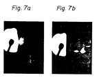
- Figures 7a and 7b show reflection electron diffraction patterns (x 400) of the Si layer before and after annealing or recrystallization, respectively.
- Figure 7a Photomicrograph for unannealed Si layer 8 in Fig. 4a
- Figure 7b which is a photomicropraph for annealed Si layer 9 in Fig. 4b, shows some spot-like luminance. From these luminances, it is ascertained that Si in the layer 9 is in a single-crystalline form.
- the annealing conditions effective to attain remarkable effects of this invention are an atmosphere of hydrogen gas and temperature range of 650°C to 1350°C.
- Figs. 8a and 8b are SEM photographs (x 20,000) of the single-crystalline Si layers of Fig. 4b with and without the layer 9, respectively.
- Figure 8a shows the occurrence and distribution of the faults in the annealed Si layer or single-crystalline layer 9. From this photograph, it can be evaluated that the density of faults is on the order of 5 x 10 4 to 5 x 10 5 cm -2 .
- Fig. 8b (prior art) has conspicuous faults of a density on the order of 10 8 to 10 9 cm -2 .
- Figure 8b is an SEM photograph of the 1.0 ⁇ m thick single-crystalline Si layer 7 of Fig. 4b having no layer 9. It is apparent from Figs.
- FIG. 5 shows another preferred embodiment of this invention.
- a third single-crystalline Si layer 10 may be formed on the Si layer 9.
- the Si layer 10 can be VPE-grown in hydrogen gas at about 950°C and at a growth rate of 0.85 pm/min.
- the thickness of the epitaxially grown Si layer 10 is about 40 ⁇ m.
- the occurrence and distribution of the faults in the third Si layer 10 are shown in the accompanying drawing, Fig. 9a, which is a photomicrograph taken at 400 magnifications. From this photograph, the fault density of the layer 10 is evaluated to be on the order of 10 to 10 cm .
- Molybdate pretreatment of the spinel layer can be carried out, for example, as follows:
- a third single-crystalline Si layer is epitaxially grown on the second single-crystalline Si layer.
- the formation of the third Si layer can be formed by using a VPE technique under the following conditions: atmosphere of mixed gas of monosilane and hydrogen; reaction temperature of about 950°C; and growth rate of about 0.85 ⁇ m/min.
- the thickness of the third Si layer is about 40 ⁇ m.
- Figure 10a is a photomicrograph (x 400) of the third Si layer of the SOI structure, from which photograph the fault density is evaluated to be on the ] order of 10 3 to 10 cm .
- the fault density of the third Si layer produced as in Figs. 4a, 4b, and 5 is determined to be on the order of 10 4 to 105 cm 2 from F ig. 10b, which is a photomicrograph (x 400) of the third Si layer.
- this invention it is proposed to interpose two or more Si buffer layers or second single-crystalline Si layers between the first and third single-crystalline Si layers.
- the formation of multiple Si buffer layers is effective to further decrease the fault density of the third Si layer produced in the above-described embodiment of this invention, namely, the order of 10 3 to 10 4 cm .
- the production process of this embodiment will be described hereinafter with reference to Figs. 11 and 12.
- a 1 ⁇ m thick single-crystalline spinel layer 5 is formed on the single-crystalline Si substrate 1.
- the Si substrate 1 with the spinel layer 5 is dipped in a solution of about 0.1 g of molybdic acid in 1 of about 30% hydrogen peroxide/water for about 30 seconds and then dried.
- a 0.5 ⁇ m thick first single-crystalline Si layer 7 is epitaxially grown on the spinel layer 5 in a mixed gas of monosilane and hydrogen at a temperature of about 950°C and at a growth rate of about.0.85 ⁇ m/min.
- a 0.5 pm thick amorphous Si layer (not shown) is epitaxially grown on the first Si layer 7 in a mixed gas of monosilane and nitrogen at a temperature of about 540°C and at a growth rate of 0 about 830 A/min.
- the amorphous Si layer is then annealed in hydrogen gas at about 1100°C for about 10 minutes.
- a second single-crystalline Si layer (first Si buffer layer) 9 is obtained.
- the above-described series of the steps of forming the amorphous Si layer and converting amorphous silicon in the layer to single-crystalline silicon is repeated to obtain an additional second single-crystalline Si layer (second Si buffer layer) 19.
- a third single-crystalline Si layer 10 is epitaxially grown on the second Si buffer layer 19 in a mixed gas of monosilane and hydrogen at a temperature of about 950°C and at a growth rate of about 0.85 pm/min.
- the thickness of the deposited third Si layer 10 is about 40 ⁇ m.
- the thus produced SOI structure shows significantly decreased fault density. Its fault density is on the order of 10 2 to 10 3 cm -2 and is evaluated from Fig. 13a, namely, the photomicrograph (400 x) of the third Si layer of the SOI structure.
- Fig. 13a namely, the photomicrograph (400 x) of the third Si layer of the SOI structure.
- Fig. 13b another photomicrograph (x 100) of the third Si layer of the SOI structure which is identical with that of Fig. 11, except for the omission of the second Si buffer layer 19, is shown in Fig. 13b.
- the fault density of the third Si layer of the latter SOI structure, as described above, is on the order of 10 3 to 10 4 cm -2 .
- Fig. 12 is a graph showing a density of stacking faults as a function of Si thickness from the interface between the spinel layer 5 and the first Si layer 7.
- the solid line I and dotted line II correspond to Figs. 13a and 13b, respectively, and points A, B, C, and D each indicates an interface between two adjacent layers.
- the duplicated Si buffer layers (Layers 9 plus 19) (Line I) indicate shaply decreased fault density.
- a 1 ⁇ m thick single-crystalline spinel layer 5 is formed on a single-crystalline Si substrate 1.
- the Si substrate 1 with the spinel layer 5 is dipped in a solution of about 0.1 g of molybdic acid in 1 1 of about 30% hydrogen peroxide/water for about 30 seconds and then dried.
- a 0.5 ⁇ m thick first single-crystalline Si layer 7 is epitaxially grown on the spinel layer 5 in a mixed gas of monosilane and hydrogen at a temperature of about 950°C and at a growth rate of about 0.85 pm/min.
- a 0.5 ⁇ m thick amorphous Si layer (not shown) is epitaxially grown on the first Si layer 7 in a mixed gas of monosilane and nitrogen at a temperature of about 540°C and at a growth rate of about 830 A/min.
- the amorphous Si layer is then annealed in hydrogen gas at about 1100°C for about 10 minutes.
- a second single-crystalline Si layer 9 is obtained.
- an additional 2 ⁇ m thick single-crystalline Si layer 11 is epitaxially grown on the second Si layer 9 in a mixed gas of monosilane and hydrogen at about 950°C and at a slow growth rate of about 0.1 ⁇ m/min.
- impurities for example, oxygen atoms, which partially occur on the surface of the second Si layer 9 and adversely affect the quality of the epitaxially grown Si crystal on the layer 9 are removed.
- a third single-crystalline Si layer 10 is epitaxially grown on the additional Si layer 11 in a mixed gas of monosilane and hydrogen at a temperature of about 950°C and at a growth rate of about 0.85 ⁇ m/min.
- the thickness of the deposited third Si layer 10 is about 40 ⁇ m.
- the thus produced SOI structure shows significantly decreased fault density. Its fault density is on the order of 10 2 to 10 3 cm -2 and is evaluated from Fig. 15a, namely, the photomicrograph (x 400) of the third Si layer of the SOI structure. For comparison purposes, another photomicrograph (x 100) of the third Si layer of the SOI structure, which is identical with that of Fig. 14 except for omission of the additional Si layer 11, is shown in Fig. 15b.
- the fault density of the third Si layer of the latter SOI structure, as described above, is on the order of 10 3 to 10 4 cm -2 .
- the additional Si layer 11 is epitaxially grown in a mixed gas of monosilane and-hydrogen.
- a mixed gas of hydrogen and silicon tetrachloride or dichlorsilane or a mixed gas of said mixed gas and hydrogen chloride is also possible to use a mixed gas of hydrogen and silicon tetrachloride or dichlorsilane or a mixed gas of said mixed gas and hydrogen chloride.
- the growth temperature and growth rate are preferably 950°C to 1150°C and 0.01 to 0.2 ⁇ m/min, respectively.
- the formation of the third Si layer 10 can be preferably carried out in a mixed gas of monosilane and hydrogen.
- gases conventionally used in this field for example, silicon tetrachloride and dichlorsilane, may be used to obtain satisfactory results.
- the epitaxial growth of amorphous silicon can be preferably carried out at a growth temperature of 350°C to 650°C ° and at a growth rate of 20 to 2000 A/min.
- Figures 16, 17, and 18 are schematic cross-sectional views showing the SOI structures with well-etched Si substrates according to this invention. Since Figs. 16, 17, and 18 correspond to Figs. 5, 11, and 14, we will omit detailed descriptions of these drawings.
Abstract
Description
- This invention relates to a process for the production of semiconductor devices. In particular, this invention relates to a process for the production of semiconductor devices which comprise a single-crystalline layer of silicon, as an active layer, on a single-crystalline layer of insulating materials such as magnesia spinel (MgO·Al2O3 ) and sapphire (a-A1203). Such an active silicon layer on an insulator or insulating layer is generally referred to in the art as an SOI (silicon-on-insulator), and is used for fabrication of bipolar transistors, metal-oxide semiconductor (MOS) devices, high-voltage bipolar integrated circuits (IC's), or similar circuits and devices.
- Many types of SOI's have been proposed and used in the production of semiconductor devices due to the advantages offered by the same. First, they do not necessitate isolation in the devices or, even if isolation is necessary, it is easy to form an isolation area. Further, semiconductor devices having SOI structures show no or little parasitic capacitance. These remarkable advantages ensure the production of semiconductor devices having a high quality and integrity.
- A typical example of the prior art SOI structure can be found in Figs. la and lb. As illustrated in Fig. la, the SOI material comprises a (100)
Si substrate 1 having deposited thereon an Si02 layer 2 and anamorphous Si layer 3. Theamorphous Si layer 3 is generally formed by using vapor phase epitaxy (VPE) or other techniques. - In order to convert amorphous Si in the
layer 3 to single-crystalline Si, the material is annealed at a temperature of about 600°C to 1100°C. Crystallization of the amorphous Si is started at an exposed portion of theSi substrate 1, as is shown in Fig. lb. Namely, the exposed portion of thesubstrate 1 acts as a seed for crystallization. The single-crystalline Si area 4 gradually extends over thelayer 3. Finally, all of amorphous Si in thelayer 3 is converted to a single-crystalline form of silicon. - The result is shown in Fig. 2, which is a schematic plane view of the resulting SOI structure. Unexpectedly, the single-
crystalline Si layer 4 has partially formed (ll0) and (111) crystal structures in addition to the (100) crystal structure. This means that thelayer 4 is not a single-crystalline form, but polycrystalline form. Such an undesirable result can be frequently encountered in the formation of the illustrated SOI structure. - Heteroepitaxy is also well-known and widely used in the formation of SOI structures. As we have already reported in, for example, M. Ihara et al., "Vapor phase epitaxial growth of MgO.Al2O3", J. Electrochem. Soc., Vol. 129, No. 11, pp. 2569-2573, Nov. 1982, and M. Ihara, "Epitaxial spinel growth for integrated circuits", Microelectronic Engineering, Vol. 1, pp. 161-177, 1983, SOI structures produced by using heteroepitaxy or the heteroepitaxial-growth technique have many advantages. For example, the resulting active Si layers on sapphire or spinel show high quality and mobility. High voltage isolation can be achieved. The large-sized Si wafers can be used as the substrate, therefore low-price devices can be produced.
- However, this technique suffers from a drawback that the active Si layers have unavoidable stacking faults due to their hetero junction with the underlying sapphire or spinel layer. This defect will become clearer with reference to Fig. 3, which illustrates a typical Si-on-spinel (MgO·Al2O3)-on-Si double heterostructure.
- In Fig. 3, the illustrated SOI structure comprises a (100) single-
crystalline Si substrate 1 having deposited thereon a (100)-oriented spinelepitaxial layer 5 and (100)-oriented single-crystalline Si layer 6. TheSi layer 6 is generally deposited by VPE. During the VPE process, stacking faults (lll) are induced in the growingSi layer 6. We found that the formation of the stacking faults is started at limited portions of the Si/spinel interface, each of which acts as a core of the fault formation during crystal growth. Such core portions are considered to be due to the about 0.8% lattice mismatch between Si and spinel. - The stacking faults result in conspicuous straight defects on a surface of the active Si layer after they have passed through the layer. This means lowering of the yield of the SOI structure and, accordingly, the finally produced devices. It is, therefore, desirable to provide improved methods for forming SOI structures which have thin or thick layers of single-crystalline Si with high quality and without stacking faults, on an insulating layer of spinel, sapphire, or other single crystals.
- According to this invention, there is provided a process for the production of semiconductor devices by using SOI techniques, which process comprises the steps of forming a first layer of single-crystalline silicon on an underlying layer of single-crystalline insulating material, forming a second layer of amorphous silicon on the-first layer of silicon, and then converting amorphous silicon of the second layer to single-crystalline silicon.
- The single-crystalline insulating material used herein can be optionally selected from the group of insulators conventionally used in the art such as sapphire, magnesia spinel, and the like, depending on the type of the desired device. For example, sapphire can be used in the form of a sapphire substrate, and magnesia spinel can be used in the form of a spinel epitaxial layer on the Si substrate. Epitaxial spinel growth on Si substrate is described in, for example, the M. Ihara references cited above. The crystal orientation of these materials is (100).
- The first layer of single-crystalline silicon can be epitaxially grown on the surface of the underlying insulator layer. Epitaxial growth of Si is preferably carried out by using conventional VPE techniques. For example, it may be carried out at a temperature of 900°C to 1100°C in a mixed gas of mono silane (SiH4) and hydrogen. The thickness of the first Si layer is preferably in the range of 0.01 to 10 pm. A layer thickness of more than 10 µm should be avoided, since it results in increased size of the stacking faults, although the number of the faults is decreased. The first Si layer has a (100) crystal structure and acts as an interfacial layer between the insulator layer and the active Si layer.
- After the formation of the first Si layer, a second layer of single-crystalline silicon, which has a (100) crystal structure and acts as a buffer layer, is formed on the first Si layer. The Si buffer layer can effectively inhibit elongation of the stacking faults caused in the underlying first Si layer within the buffer layer and, if an active Si layer is formed on the buffer layer, extension of the faults to the active Si layer.
- As described above, the formation of the second Si layer comprises a series of two steps. First, an amorphous silicon layer is preferably formed on the first Si layer by using conventional VPE techniques at a reaction temperature of 350°C to 650°C in an atmosphere of inert gas such as
N 2 Ar, or He or inert gas-based mixed gas which comprises a major amount of inert gas and a minor amount of other gas such as H2. Monosilane is added to the atmosphere. The formation of the amorphous Si layer in this step can be easily carried out under the above reaction conditions. - In the above first step, hydrogen in the mixed gas is effective to prevent the influence of oxygen gas which is contained as impurities in an inert gas. If the impure inert gas has no hydrogen gas, oxygen gas will form silicon dioxide as a result of the reaction with silicon. The amount of hydrogen gas to be added to the inert gas is not critical, but is preferably less than 30% of the total amount of the mixed gas.
- Further, the reaction temperature of 350°C to 650°C is essential to ensure the formation of amorphous silicon in the above first step. If the reaction temperature is lower than 350°C, the decomposition of monosilane will not be started. Namely, the following reaction is not substantially induced:
SiH4 + Si + 2H 2 On the other hand, if the reaction temperature exceeds 650°C, polycrystalline silicon will be formed between about 650°C and 850°C, and single-crystalline silicon at about 850°C or more, respectively. - As a second step, the epitaxially grown amorphous silicon on the first Si layer is annealed at a temperature of 650°C to 1350°C in an atmosphere of hydrogen gas with conventional SPE techniques to convert it to single-crystalline silicon. The conversion process is also referred to in this art as a "recrystallization" process. The annealing temperature of 650°C to 1350°C is effective to shorten the time of the recrystallization process and to produce the second single-crystalline Si layer having little or no defects.
- In the formation of the second Si layer, the layer thickness of the amorphous silicon formed in the first step is preferably within the range of-0.01 to 5 pm. A layer thickness of more than 5 µm should be avoided, since it tends to cause polycrystallization of the amorphous silicon during the second step or the subsequent annealing step for recrystallization.
- In an aspect of this invention, the production process further comprises the step of forming a third layer of single-crystalline silicon on the second layer of single-crystalline silicon. The third Si layer is generally recognized in this art to be an active Si layer and has a (100) crystal structure, as in the underlying first and second Si layers. The third Si layer can be formed in conventional manners, such as by VPE techniques, frequently used in the formation of single-crystalline silicon. For example, it may be epitaxially grown on the second Si layer in a mixed gas of SiH4 or SiC14 and H2 and at a growth temperature of 900°C to 1100°C. The growth rates of single-crystalline Si or active Si are about 0.2 to 3 um/min. The layer thickness of the epitaxially grown Si varies depending on the requirements of the finally produced devices.
- In another aspect of this invention, a surface of the layer of single-crystalline insulating material is pretreated with a solution of 1 to 0.01 g of molybdic acid in 1 X of 30% hydrogen peroxide water, before the deposition of the first Si layer thereon. As a result of pretreatment of the insulator layer, the density of the defects caused in the first Si layer is remarkably decreased and consequently an SOI structure of a high quality is produced. This is because the introduction of a lot of molybdenum cores in the insulator layer results in more complete formation of the first Si layer, i.e., heteroepitaxially grown Si layer, on the insulator layer.
- In another aspect of this invention, second, two or more single-crystalline silicon layers may be formed, thereby increasing the quality of the third Si layer which is subsequently formed on the second Si layer.
- In other words, the steps of forming the second layer of amorphous silicon and converting amorphous silicon in the second layer to single-crystalline silicon may be repeated two or more times.
- In still another aspect of this invention, the production process may further comprise the step of forming, before the formation of the third layer of silicon on the second layer of silicon, an additional layer of single-crystalline silicon on the second layer of silicon, the additional layer being formed at a growth rate slower than that of the third layer. The formation of the slowly grown single-crystalline silicon layer is particularly effective to remove contaminants on the second Si layer, which are induced due to exposure to hydrogen gas during the annealing step and are one factor of increasing stacking faults in the third Si layer to be deposited on the second Si layer. Contaminants partially distributed on the second Si layer are oxygen atoms and the like. The removal step can be easily carried out in comparison with the conventional purification step which comprises etching the second Si layer to a depth sufficient to remove the contaminants.
- The additional layer of slowly grown silicon can be formed by using conventional VPE techniques as in the formation of the third Si layer described above. In contrast with the growth rates of single-crystalline Si for the third Si layer, which rates, as previously described, are about 0.2 to 3 pm/min, the growth rates of single-crystalline Si for the additional Si layer are generally about 0.01 to 0.2 um/min. The thickness of the additional Si layer of about 0.5 to 2 µm is sufficient to substantially remove the contaminants on the second Si layer.
- As is apparent from the above description, according to this invention, semiconductor devices which comprise a single-crystalline insulator layer, such as spinel or sapphire, having deposited thereon thin or thick single-crystalline Si layers with high quality and without stacking faults can be produced with high yields.
-
- Figures la and lb are schematic cross-sectional views showing, in sequence, the production of a prior art SOI structure;
- Fig. 2 is a plane view showing the crystal orientation of the active Si layer of the prior art SOI structure according to Figs. la and lb;
- Fig. 3 is a schematic cross-sectional view showing another prior art SOI structure;
- Figs. 4a and 4b are schematic cross-sectional views showing, in sequence, the production of the SOI structure according to one embodiment of this invention;
- Fig. 5 is a schematic cross-sectional view showing the SOI structure according to another embodiment of this invention;
- Figs. 6a and 6b are photo-micrographs (x 400) of the single-crystalline Si layer showing occurrence and distribution of the faults therein;
- Figs. 7a and 7b are reflection electron diffraction patterns (x 400) of the Si layer before and after annealing, respectively;
- Figs. 8a and 8b are SEM photographs (x 20,000) of the single-crystalline Si layers with and without an annealed Si layer, respectively;
- Figs. 9a and 9b are photo-micrographs (x 400) of the single-crystalline Si layer according to this invention and the prior art, respectively;
- Figs. 10a and 10b are photo-micrographs (x 400) of the molybdate-treated and untreated single-crystalline Si layers according to this invention, respectively;
- Fig. 11 is a schematic cross-sectional view of the SOI structure according to another embodiment of this invention;
- Fig. 12 is a graph of fault density as a function of Si thickness from the Si/spinel interface;
- Figs. 13a and 13b are photo-micrographs (x 400) of the single-crystalline Si layers with two Si buffer layers and with a single Si buffer layer according to this invention, respectively;
- Fig. 14 is a schematic cross-sectional view showing the SOI structure according to still another embodiment of this invention;
- Figs. 15a and 15b are micro-photographs (x 100) of the single-crystalline Si layers with and without the slowly grown Si layer according to this invention, respectively; and
- Figs. 16, 17, and 18 are each a schematic cross-sectional view of the SOI structure with a well-etched Si substrate according to preferred embodiments of this invention.
- This invention will be further described with reference to Figs. 4a to 18. First, it should be understood that the insulator used in the practice of this invention is not limited to magnesia spinel, though the drawings are explained referring to the spinel insulator.
- Referring now to Figs. 4a and 4b, there is illustrated one preferred embodiment of this invention. As is illustrated in Fig. 4a, a single-
crystalline spinel layer 5 having a thickness of about 1 pm is epitaxially grown on a single-crystalline Si substrate 1. A first single-crystalline Si layer 7 having a thickness of 0.5 µm is then formed on thespinel layer 5. The formation of thefirst Si layer 7 is attained with conventional methods, for example, epitaxial growth, at a temperature of 900°C to 950°C and in a mixed gas of monosilane and hydrogen. During the epitaxy process, some defects will be induced in the resulting Si layer, since its lower surface is a hetero-interface. In order to obtain the optimum effects of this invention, it is desirable to make the thickness of the first Si layer from 0.01 µm to 10 pm. - After the formation of the
first Si layer 7, anamorphous Si layer 8 of a thickness of about 0.5 µm is deposited on thelayer 7. Theamorphous Si layer 8 can be deposited in a conventional VPE manner under the following conditions: mixed gas of monosilane and nitrogen; reaction temperature of ° about 540°C; and growth rates of about 830A/min. Useful carrier gases other than nitrogen gas are helium or other inert gases. The useful range of the reaction temperature is from 350°C to 650°C. - The deposited
amorphous Si layer 8 is then annealed in hydrogen gas at about 11000C and for about 10 min. Upon annealing, as is shown in Fig. 4b, amorphous silicon in thelayer 8 is converted to single-crystalline silicon 9. While the prior annealing process is usually carried out in an atmosphere of helium or other inert gases, the annealing process of this invention is carried out in hydrogen gas. We found that stacking faults in the single-crystalline Si layer to be deposited on the thus converted single-crystalline Si layer 9 are notably decreased if annealing is performed in hydrogen gas. In contrast, annealing in an inert gas results in a lot of stacking faults in the single-crystalline Si layer. These differences of the results are demonstrated in Fig. 6a (prior art; annealing in He) and Fig. 6b (this invention; annealing in H2), both of which are photo-micrographs (x 400) of the single-crystalline Si layer showing occurrence and distribution of the faults therein. Figure 6a shows many faults, while Fig. 6b shows decreased faults. - Figures 7a and 7b show reflection electron diffraction patterns (x 400) of the Si layer before and after annealing or recrystallization, respectively. Figure 7a (Photomicrograph for
unannealed Si layer 8 in Fig. 4a) shows neither spots nor rings. This demonstrates that theunannealed Si layer 8 is an amorphous form. Figure 7b, which is a photomicropraph for annealedSi layer 9 in Fig. 4b, shows some spot-like luminance. From these luminances, it is ascertained that Si in thelayer 9 is in a single-crystalline form. As previously described, the annealing conditions effective to attain remarkable effects of this invention are an atmosphere of hydrogen gas and temperature range of 650°C to 1350°C. - Further, Figs. 8a and 8b are SEM photographs (x 20,000) of the single-crystalline Si layers of Fig. 4b with and without the
layer 9, respectively. Figure 8a shows the occurrence and distribution of the faults in the annealed Si layer or single-crystalline layer 9. From this photograph, it can be evaluated that the density of faults is on the order of 5 x 10⁴ to 5 x 105 cm-2. In contrast, Fig. 8b (prior art) has conspicuous faults of a density on the order of 10 8 to 109 cm-2. Figure 8b is an SEM photograph of the 1.0 µm thick single-crystalline Si layer 7 of Fig. 4b having nolayer 9. It is apparent from Figs. 8a and 8b that stacking faults in the single-crystalline Si layers are remarkably decreased, if the secondamorphous Si layer 8 is first formed on the first single-crystalline Si layer 7 and is then recrystallized to the second single-crystalline Si layer 9 according to this invention (see Figs. 4a and 4b). - Figure 5 shows another preferred embodiment of this invention. As is shown in this figure, upon formation of the single-
crystalline Si layer 9, a third single-crystalline Si layer 10 may be formed on theSi layer 9. TheSi layer 10 can be VPE-grown in hydrogen gas at about 950°C and at a growth rate of 0.85 pm/min. The thickness of the epitaxially grownSi layer 10 is about 40 µm. The occurrence and distribution of the faults in thethird Si layer 10 are shown in the accompanying drawing, Fig. 9a, which is a photomicrograph taken at 400 magnifications. From this photograph, the fault density of thelayer 10 is evaluated to be on the order of 10 to 10 cm . For comparison purposes, we took a photomicrograph (x 400) of the single-crystalline Si layer directly grown on the magnesia spinel (prior art SOI structure). The photograph of Fig. 9b shows that the prior art Si layer has many faults and its fault density is on the order of 105 to 106 cm-2. From these photographs, it is clear that this invention can notably improve the fault density of the Si layers on the spinel. - According to another preferred embodiment of this invention, in order to further decrease the fault density, thereby producing a single-crystalline Si layer with excellent quality, it is proposed to previously treat a surface of the magnesia spinel layer with a solution of molybdate. Molybdate pretreatment of the spinel layer can be carried out, for example, as follows:
- As in the production process which was described with reference to Figs. 4a, 4B, and 5, a 1 µm thick single-crystalline spinel layer is epitaxially grown on the single-crystalline Si substrate. The Si substrate with the grown spinel layer is then dipped in a solution of about 0.1 g of molybdic acid in 1 ℓ of about 30% hydrogen peroxide/water for about 30 seconds. After drying, as in the previously described production process, a 0.5 µm thick first single-crystalline Si layer is epitaxially grown on the dried spinel layer by using a VPE technique under the following conditions: atmosphere of mixed gas of monosilane and hydrogen; reaction temperature of about 950°C; and growth rate of about 0.85 µm/min. Then, a 0.5 µm thick amorphous Si layer is epitaxially grown on the first single-crystalline Si layer by using a VPE technique. The epitaxial growth can be carried out in a mixed gas of monosilane and nitrogen at a reaction temperature of 0 about 540°C and at a growth rate of about 830 A/min. The epitaxially grown amorphous Si layer is then annealed in hydrogen gas at about 1100°C for about 10 minutes to convert it to the second single-crystalline Si layer.
- After the conversion process is completed, a third single-crystalline Si layer is epitaxially grown on the second single-crystalline Si layer. The formation of the third Si layer can be formed by using a VPE technique under the following conditions: atmosphere of mixed gas of monosilane and hydrogen; reaction temperature of about 950°C; and growth rate of about 0.85 µm/min. The thickness of the third Si layer is about 40 µm.
- The thus produced SOI structure has only few stacking faults. Figure 10a is a photomicrograph (x 400) of the third Si layer of the SOI structure, from which photograph the fault density is evaluated to be on the ] order of 103 to 10 cm . In contrast to this, the fault density of the third Si layer produced as in Figs. 4a, 4b, and 5 is determined to be on the order of 104 to 105
cm 2 from Fig. 10b, which is a photomicrograph (x 400) of the third Si layer. - According to still another preferred embodiment of this invention, it is proposed to interpose two or more Si buffer layers or second single-crystalline Si layers between the first and third single-crystalline Si layers. Unexpectedly, we found that the formation of multiple Si buffer layers is effective to further decrease the fault density of the third Si layer produced in the above-described embodiment of this invention, namely, the order of 103 to 104 cm . The production process of this embodiment will be described hereinafter with reference to Figs. 11 and 12.
- As in the last described production process, which includes pretreatment of the spinel layer with nolybdate, a 1 µm thick single-
crystalline spinel layer 5 is formed on the single-crystalline Si substrate 1. TheSi substrate 1 with thespinel layer 5 is dipped in a solution of about 0.1 g of molybdic acid in 1 of about 30% hydrogen peroxide/water for about 30 seconds and then dried. After drying, a 0.5 µm thick first single-crystalline Si layer 7 is epitaxially grown on thespinel layer 5 in a mixed gas of monosilane and hydrogen at a temperature of about 950°C and at a growth rate of about.0.85 µm/min. Thereafter, a 0.5 pm thick amorphous Si layer (not shown) is epitaxially grown on thefirst Si layer 7 in a mixed gas of monosilane and nitrogen at a temperature of about 540°C and at a growth rate of 0 about 830 A/min. The amorphous Si layer is then annealed in hydrogen gas at about 1100°C for about 10 minutes. As a result of conversion of amorphous silicon to single-crystalline silicon, a second single-crystalline Si layer (first Si buffer layer) 9 is obtained. Further, the above-described series of the steps of forming the amorphous Si layer and converting amorphous silicon in the layer to single-crystalline silicon is repeated to obtain an additional second single-crystalline Si layer (second Si buffer layer) 19. Finally, a third single-crystalline Si layer 10 is epitaxially grown on the secondSi buffer layer 19 in a mixed gas of monosilane and hydrogen at a temperature of about 950°C and at a growth rate of about 0.85 pm/min. The thickness of the depositedthird Si layer 10 is about 40 µm. - The thus produced SOI structure shows significantly decreased fault density. Its fault density is on the order of 10 2 to 103 cm-2 and is evaluated from Fig. 13a, namely, the photomicrograph (400 x) of the third Si layer of the SOI structure. For comparison purposes, another photomicrograph (x 100) of the third Si layer of the SOI structure which is identical with that of Fig. 11, except for the omission of the second
Si buffer layer 19, is shown in Fig. 13b. The fault density of the third Si layer of the latter SOI structure, as described above, is on the order of 103 to 10 4 cm-2. - Effects of the duplicated Si buffer layers 9 and 19 will be further clarified with reference to Fig. 12, which is a graph showing a density of stacking faults as a function of Si thickness from the interface between the
spinel layer 5 and thefirst Si layer 7. The solid line I and dotted line II correspond to Figs. 13a and 13b, respectively, and points A, B, C, and D each indicates an interface between two adjacent layers. In contrast to the single Si buffer layer (Line II), the duplicated Si buffer layers (Layers 9 plus 19) (Line I) indicate shaply decreased fault density. - In another preferred embodiment of this invention, it is also proposed to interpose an additional slowly grown single-crystalline Si layer between the second Si buffer layer and the third Si layer. This process is effective to further decrease the fault density of the third Si layer of the molybdate-pretreated spinel layer-containing SOI structure described above, namely, the order of 103 to 104 cm-2. Details of this process will be described hereinbelow with reference to Fig. 14.
- As in the previously described production of the molybdate-pretreated spinel layer-containing SOI structure, a 1 µm thick single-
crystalline spinel layer 5 is formed on a single-crystalline Si substrate 1. TheSi substrate 1 with thespinel layer 5 is dipped in a solution of about 0.1 g of molybdic acid in 1 1 of about 30% hydrogen peroxide/water for about 30 seconds and then dried. After drying, a 0.5 µm thick first single-crystalline Si layer 7 is epitaxially grown on thespinel layer 5 in a mixed gas of monosilane and hydrogen at a temperature of about 950°C and at a growth rate of about 0.85 pm/min. Thereafter, a 0.5 µm thick amorphous Si layer (not shown) is epitaxially grown on thefirst Si layer 7 in a mixed gas of monosilane and nitrogen at a temperature of about 540°C and at a growth rate of about 830 A/min. The amorphous Si layer is then annealed in hydrogen gas at about 1100°C for about 10 minutes. As a result of conversion of amorphous silicon to single-crystalline silicon, a second single-crystalline Si layer 9 is obtained. - Then, an additional 2 µm thick single-
crystalline Si layer 11 is epitaxially grown on thesecond Si layer 9 in a mixed gas of monosilane and hydrogen at about 950°C and at a slow growth rate of about 0.1 µm/min. As a result, impurities, for example, oxygen atoms, which partially occur on the surface of thesecond Si layer 9 and adversely affect the quality of the epitaxially grown Si crystal on thelayer 9 are removed. Finally, a third single-crystalline Si layer 10 is epitaxially grown on theadditional Si layer 11 in a mixed gas of monosilane and hydrogen at a temperature of about 950°C and at a growth rate of about 0.85 µm/min. The thickness of the depositedthird Si layer 10 is about 40 µm. - The thus produced SOI structure shows significantly decreased fault density. Its fault density is on the order of 102 to 103 cm-2 and is evaluated from Fig. 15a, namely, the photomicrograph (x 400) of the third Si layer of the SOI structure. For comparison purposes, another photomicrograph (x 100) of the third Si layer of the SOI structure, which is identical with that of Fig. 14 except for omission of the
additional Si layer 11, is shown in Fig. 15b. The fault density of the third Si layer of the latter SOI structure, as described above, is on the order of 103 to 104 cm-2. - In the production process described above, the
additional Si layer 11 is epitaxially grown in a mixed gas of monosilane and-hydrogen. However, in addition to this mixed gas, it is also possible to use a mixed gas of hydrogen and silicon tetrachloride or dichlorsilane or a mixed gas of said mixed gas and hydrogen chloride. The growth temperature and growth rate are preferably 950°C to 1150°C and 0.01 to 0.2 µm/min, respectively. - Further, as previously described, the formation of the
third Si layer 10 can be preferably carried out in a mixed gas of monosilane and hydrogen. Similarly, other gases conventionally used in this field, for example, silicon tetrachloride and dichlorsilane, may be used to obtain satisfactory results. - Furthermore, it was found from experiments that the epitaxial growth of amorphous silicon can be preferably carried out at a growth temperature of 350°C to 650°C ° and at a growth rate of 20 to 2000 A/min.
- Figures 16, 17, and 18 are schematic cross-sectional views showing the SOI structures with well-etched Si substrates according to this invention. Since Figs. 16, 17, and 18 correspond to Figs. 5, 11, and 14, we will omit detailed descriptions of these drawings.
Claims (7)
Applications Claiming Priority (2)
| Application Number | Priority Date | Filing Date | Title |
|---|---|---|---|
| JP59060403A JPS60202952A (en) | 1984-03-28 | 1984-03-28 | Manufacture of semiconductor device |
| JP60403/84 | 1984-03-28 |
Publications (3)
| Publication Number | Publication Date |
|---|---|
| EP0159252A2 true EP0159252A2 (en) | 1985-10-23 |
| EP0159252A3 EP0159252A3 (en) | 1988-09-28 |
| EP0159252B1 EP0159252B1 (en) | 1993-06-02 |
Family
ID=13141166
Family Applications (1)
| Application Number | Title | Priority Date | Filing Date |
|---|---|---|---|
| EP85400604A Expired - Lifetime EP0159252B1 (en) | 1984-03-28 | 1985-03-28 | Process for the production of semiconductor devices by using silicon-on-isolation techniques |
Country Status (5)
| Country | Link |
|---|---|
| US (1) | US5037774A (en) |
| EP (1) | EP0159252B1 (en) |
| JP (1) | JPS60202952A (en) |
| KR (1) | KR900000203B1 (en) |
| DE (1) | DE3587377T2 (en) |
Cited By (2)
| Publication number | Priority date | Publication date | Assignee | Title |
|---|---|---|---|---|
| EP0257917A2 (en) * | 1986-08-20 | 1988-03-02 | AT&T Corp. | Method of producing soi devices |
| EP0342937A1 (en) * | 1988-05-17 | 1989-11-23 | Fujitsu Limited | Manufacturing a semiconductor wafer having a III-V group semiconductor compound layer on a silicon substrate |
Families Citing this family (24)
| Publication number | Priority date | Publication date | Assignee | Title |
|---|---|---|---|---|
| JPH01244608A (en) * | 1988-03-26 | 1989-09-29 | Fujitsu Ltd | Process of growing semiconductor crystal |
| US5310696A (en) * | 1989-06-16 | 1994-05-10 | Massachusetts Institute Of Technology | Chemical method for the modification of a substrate surface to accomplish heteroepitaxial crystal growth |
| US5444302A (en) * | 1992-12-25 | 1995-08-22 | Hitachi, Ltd. | Semiconductor device including multi-layer conductive thin film of polycrystalline material |
| US5843225A (en) * | 1993-02-03 | 1998-12-01 | Semiconductor Energy Laboratory Co., Ltd. | Process for fabricating semiconductor and process for fabricating semiconductor device |
| JP3497198B2 (en) * | 1993-02-03 | 2004-02-16 | 株式会社半導体エネルギー研究所 | Method for manufacturing semiconductor device and thin film transistor |
| US6997985B1 (en) | 1993-02-15 | 2006-02-14 | Semiconductor Energy Laboratory Co., Ltd. | Semiconductor, semiconductor device, and method for fabricating the same |
| EP0612102B1 (en) * | 1993-02-15 | 2001-09-26 | Semiconductor Energy Laboratory Co., Ltd. | Process for the fabrication of a crystallised semiconductor layer |
| JPH0794420A (en) * | 1993-09-20 | 1995-04-07 | Fujitsu Ltd | Manufacture of compound semiconductor crystal substrate |
| US5402749A (en) * | 1994-05-03 | 1995-04-04 | The United States Of America As Represented By The Secretary Of The Navy | Ultra-high vacuum/chemical vapor deposition of epitaxial silicon-on-sapphire |
| US5915174A (en) | 1994-09-30 | 1999-06-22 | Semiconductor Energy Laboratory Co., Ltd. | Semiconductor device and method for producing the same |
| US5893948A (en) * | 1996-04-05 | 1999-04-13 | Xerox Corporation | Method for forming single silicon crystals using nucleation sites |
| US5733641A (en) * | 1996-05-31 | 1998-03-31 | Xerox Corporation | Buffered substrate for semiconductor devices |
| US6501094B1 (en) * | 1997-06-11 | 2002-12-31 | Semiconductor Energy Laboratory Co., Ltd. | Semiconductor device comprising a bottom gate type thin film transistor |
| US6037199A (en) * | 1999-08-16 | 2000-03-14 | Taiwan Semiconductor Manufacturing Company, Ltd. | SOI device for DRAM cells beyond gigabit generation and method for making the same |
| DE10025871A1 (en) * | 2000-05-25 | 2001-12-06 | Wacker Siltronic Halbleitermat | Epitaxial semiconductor wafer and method for its production |
| US6852575B2 (en) * | 2001-07-05 | 2005-02-08 | International Business Machines Corporation | Method of forming lattice-matched structure on silicon and structure formed thereby |
| US6933566B2 (en) * | 2001-07-05 | 2005-08-23 | International Business Machines Corporation | Method of forming lattice-matched structure on silicon and structure formed thereby |
| US6787433B2 (en) * | 2001-09-19 | 2004-09-07 | Kabushiki Kaisha Toshiba | Semiconductor device and method of manufacturing the same |
| US7452757B2 (en) * | 2002-05-07 | 2008-11-18 | Asm America, Inc. | Silicon-on-insulator structures and methods |
| JP2004165351A (en) * | 2002-11-12 | 2004-06-10 | Fujitsu Ltd | Method for manufacturing semiconductor device |
| DE102005009725A1 (en) * | 2005-03-03 | 2006-09-07 | Atmel Germany Gmbh | Method for integrating two bipolar transistors into a semiconductor body, semiconductor arrangement in a semiconductor body and cascode connection |
| EP2206808B1 (en) * | 2008-12-23 | 2017-07-12 | Imec | Method for manufacturing a mono-crystalline semiconductor layer on a substrate |
| US8592294B2 (en) * | 2010-02-22 | 2013-11-26 | Asm International N.V. | High temperature atomic layer deposition of dielectric oxides |
| US10002780B2 (en) * | 2016-05-17 | 2018-06-19 | Taiwan Semiconductor Manufacturing Company Ltd. | Method of manufacturing a semiconductor structure |
Citations (4)
| Publication number | Priority date | Publication date | Assignee | Title |
|---|---|---|---|---|
| US4046618A (en) * | 1972-12-29 | 1977-09-06 | International Business Machines Corporation | Method for preparing large single crystal thin films |
| US4147584A (en) * | 1977-12-27 | 1979-04-03 | Burroughs Corporation | Method for providing low cost wafers for use as substrates for integrated circuits |
| US4177321A (en) * | 1972-07-25 | 1979-12-04 | Semiconductor Research Foundation | Single crystal of semiconductive material on crystal of insulating material |
| EP0051249A2 (en) * | 1980-11-03 | 1982-05-12 | International Business Machines Corporation | Process for forming epitaxially extended polycrystalline structures |
Family Cites Families (6)
| Publication number | Priority date | Publication date | Assignee | Title |
|---|---|---|---|---|
| FR1597033A (en) * | 1968-06-19 | 1970-06-22 | ||
| US3862859A (en) * | 1972-01-10 | 1975-01-28 | Rca Corp | Method of making a semiconductor device |
| JPS5541709A (en) * | 1978-09-16 | 1980-03-24 | Chiyou Lsi Gijutsu Kenkyu Kumiai | Sos semiconductor base |
| US4381201A (en) * | 1980-03-11 | 1983-04-26 | Fujitsu Limited | Method for production of semiconductor devices |
| US4279688A (en) * | 1980-03-17 | 1981-07-21 | Rca Corporation | Method of improving silicon crystal perfection in silicon on sapphire devices |
| US4448632A (en) * | 1981-05-25 | 1984-05-15 | Mitsubishi Denki Kabushiki Kaisha | Method of fabricating semiconductor devices |
-
1984
- 1984-03-28 JP JP59060403A patent/JPS60202952A/en active Granted
-
1985
- 1985-03-28 KR KR1019850002066A patent/KR900000203B1/en not_active IP Right Cessation
- 1985-03-28 EP EP85400604A patent/EP0159252B1/en not_active Expired - Lifetime
- 1985-03-28 DE DE8585400604T patent/DE3587377T2/en not_active Expired - Lifetime
-
1987
- 1987-07-15 US US07/073,839 patent/US5037774A/en not_active Expired - Lifetime
Patent Citations (4)
| Publication number | Priority date | Publication date | Assignee | Title |
|---|---|---|---|---|
| US4177321A (en) * | 1972-07-25 | 1979-12-04 | Semiconductor Research Foundation | Single crystal of semiconductive material on crystal of insulating material |
| US4046618A (en) * | 1972-12-29 | 1977-09-06 | International Business Machines Corporation | Method for preparing large single crystal thin films |
| US4147584A (en) * | 1977-12-27 | 1979-04-03 | Burroughs Corporation | Method for providing low cost wafers for use as substrates for integrated circuits |
| EP0051249A2 (en) * | 1980-11-03 | 1982-05-12 | International Business Machines Corporation | Process for forming epitaxially extended polycrystalline structures |
Cited By (4)
| Publication number | Priority date | Publication date | Assignee | Title |
|---|---|---|---|---|
| EP0257917A2 (en) * | 1986-08-20 | 1988-03-02 | AT&T Corp. | Method of producing soi devices |
| EP0257917A3 (en) * | 1986-08-20 | 1989-03-22 | AT&T Corp. | Method of producing soi devices |
| EP0342937A1 (en) * | 1988-05-17 | 1989-11-23 | Fujitsu Limited | Manufacturing a semiconductor wafer having a III-V group semiconductor compound layer on a silicon substrate |
| US5019529A (en) * | 1988-05-17 | 1991-05-28 | Fujitsu Limited | Heteroepitaxial growth method |
Also Published As
| Publication number | Publication date |
|---|---|
| KR900000203B1 (en) | 1990-01-23 |
| US5037774A (en) | 1991-08-06 |
| EP0159252B1 (en) | 1993-06-02 |
| KR850006646A (en) | 1985-10-14 |
| EP0159252A3 (en) | 1988-09-28 |
| JPH0542824B2 (en) | 1993-06-29 |
| DE3587377T2 (en) | 1993-09-23 |
| JPS60202952A (en) | 1985-10-14 |
| DE3587377D1 (en) | 1993-07-08 |
Similar Documents
| Publication | Publication Date | Title |
|---|---|---|
| US5037774A (en) | Process for the production of semiconductor devices utilizing multi-step deposition and recrystallization of amorphous silicon | |
| US5760426A (en) | Heteroepitaxial semiconductor device including silicon substrate, GaAs layer and GaN layer #13 | |
| US8043929B2 (en) | Semiconductor substrate and method for production thereof | |
| JPH076950A (en) | Manufacture of structural parts for electron, lightning and optical constituent | |
| JPH01289108A (en) | Heteroepitaxy | |
| EP0501119B1 (en) | Method of producing semiconductor substrate | |
| US7723214B2 (en) | Multilayer structure comprising a substrate and a layer of silicon and germanium deposited heteroepitaxially thereon, and a process for producing it | |
| EP0449589A1 (en) | Method of producing a SOI structure | |
| US7749817B2 (en) | Single-crystal layer on a dielectric layer | |
| US7112243B2 (en) | Method for producing Group III nitride compound semiconductor | |
| JPH11233440A (en) | Semiconductor device | |
| JPH04206932A (en) | Semiconductor device and manufacture thereof | |
| JPS6191917A (en) | Manufacture of semiconductor thin film crystal | |
| JP3157280B2 (en) | Method for manufacturing semiconductor device | |
| JPS60145625A (en) | Manufacture of semiconductor device | |
| JPH0660401B2 (en) | Silicon thin film manufacturing method | |
| JPS5982744A (en) | Manufacture of sos substrate | |
| JPH0425135A (en) | Semiconductor substrate | |
| JPH09213635A (en) | Formation of heteroepitaxial semiconductor substrate, compound semiconductor device having the substrate and its manufacture | |
| JPH057359B2 (en) | ||
| JP2696928B2 (en) | Heteroepitaxial growth method | |
| JPH04241413A (en) | Semiconductor substrate, its manufacture, and semiconductor device | |
| JPS62183138A (en) | Element isolation of semiconductor device | |
| JPS63224213A (en) | Thin film single crystal silicon substrate | |
| JPH05259071A (en) | Epitaxial wafer and manufacture thereof |
Legal Events
| Date | Code | Title | Description |
|---|---|---|---|
| PUAI | Public reference made under article 153(3) epc to a published international application that has entered the european phase |
Free format text: ORIGINAL CODE: 0009012 |
|
| AK | Designated contracting states |
Designated state(s): DE FR GB |
|
| PUAL | Search report despatched |
Free format text: ORIGINAL CODE: 0009013 |
|
| AK | Designated contracting states |
Kind code of ref document: A3 Designated state(s): DE FR GB |
|
| 17P | Request for examination filed |
Effective date: 19881115 |
|
| 17Q | First examination report despatched |
Effective date: 19901210 |
|
| GRAA | (expected) grant |
Free format text: ORIGINAL CODE: 0009210 |
|
| AK | Designated contracting states |
Kind code of ref document: B1 Designated state(s): DE FR GB |
|
| REF | Corresponds to: |
Ref document number: 3587377 Country of ref document: DE Date of ref document: 19930708 |
|
| ET | Fr: translation filed | ||
| PLBE | No opposition filed within time limit |
Free format text: ORIGINAL CODE: 0009261 |
|
| STAA | Information on the status of an ep patent application or granted ep patent |
Free format text: STATUS: NO OPPOSITION FILED WITHIN TIME LIMIT |
|
| 26N | No opposition filed | ||
| REG | Reference to a national code |
Ref country code: GB Ref legal event code: IF02 |
|
| PGFP | Annual fee paid to national office [announced via postgrant information from national office to epo] |
Ref country code: GB Payment date: 20020327 Year of fee payment: 18 |
|
| PG25 | Lapsed in a contracting state [announced via postgrant information from national office to epo] |
Ref country code: GB Free format text: LAPSE BECAUSE OF NON-PAYMENT OF DUE FEES Effective date: 20030328 |
|
| GBPC | Gb: european patent ceased through non-payment of renewal fee |
Effective date: 20030328 |
|
| PGFP | Annual fee paid to national office [announced via postgrant information from national office to epo] |
Ref country code: FR Payment date: 20040309 Year of fee payment: 20 |
|
| PGFP | Annual fee paid to national office [announced via postgrant information from national office to epo] |
Ref country code: DE Payment date: 20040408 Year of fee payment: 20 |