EP0158091B1 - Raumheizelement, bestehend aus einem mit einer elektrischen Widerstandsbeschichtung versehenen keramischen Formkörper und Verfahren zu seiner Herstellung - Google Patents
Raumheizelement, bestehend aus einem mit einer elektrischen Widerstandsbeschichtung versehenen keramischen Formkörper und Verfahren zu seiner Herstellung Download PDFInfo
- Publication number
- EP0158091B1 EP0158091B1 EP19850102230 EP85102230A EP0158091B1 EP 0158091 B1 EP0158091 B1 EP 0158091B1 EP 19850102230 EP19850102230 EP 19850102230 EP 85102230 A EP85102230 A EP 85102230A EP 0158091 B1 EP0158091 B1 EP 0158091B1
- Authority
- EP
- European Patent Office
- Prior art keywords
- layer
- heating element
- electrically
- resistive
- room heating
- Prior art date
- Legal status (The legal status is an assumption and is not a legal conclusion. Google has not performed a legal analysis and makes no representation as to the accuracy of the status listed.)
- Expired
Links
Images


Classifications
-
- H—ELECTRICITY
- H05—ELECTRIC TECHNIQUES NOT OTHERWISE PROVIDED FOR
- H05B—ELECTRIC HEATING; ELECTRIC LIGHT SOURCES NOT OTHERWISE PROVIDED FOR; CIRCUIT ARRANGEMENTS FOR ELECTRIC LIGHT SOURCES, IN GENERAL
- H05B3/00—Ohmic-resistance heating
- H05B3/20—Heating elements having extended surface area substantially in a two-dimensional [2D] plane, e.g. plate-heater
- H05B3/22—Heating elements having extended surface area substantially in a two-dimensional [2D] plane, e.g. plate-heater non-flexible
- H05B3/26—Heating elements having extended surface area substantially in a two-dimensional [2D] plane, e.g. plate-heater non-flexible heating conductor mounted on insulating base
- H05B3/265—Heating elements having extended surface area substantially in a two-dimensional [2D] plane, e.g. plate-heater non-flexible heating conductor mounted on insulating base the insulating base being an inorganic material, e.g. ceramic
Definitions
- the invention relates to a space heating element according to the preamble of claim 1.
- the elements used for space heating are in the form of finned radiators or surface radiators, generally located below window openings, so that the room air heated by them rises above the window openings and thus generates a warm air curtain in front of the window opening. Even when radiators are installed on walls, there is an air movement from the floor to the ceiling of the room heated with them, the heat radiated into the room by the radiator only playing a minor role.
- Standard pure radiant heaters installed in rooms only have a locally very limited radiation area and work at high temperatures.
- the prior art also includes underfloor heating systems in which heating coils acted upon by liquid heat transfer medium, but also electrical heating conductors, are accommodated in the screed or below the top floor covering.
- Underfloor heating systems are comparatively cumbersome and expensive to build and require comparatively complex controls.
- Ceramic moldings such as plates, which serve as floor or wall cladding panels for the design of the walls or the floor or the ceiling of living, business and office spaces, but also of sanitary rooms, sports and swimming pools serve.
- Such ceramic moldings can also be shaped stones for swimming pool linings and the like. be.
- This heating lacquer layer is covered by a polyurethane foam body.
- this system could not prevail because local overheating occurred repeatedly with the resulting harmful extensions, which even put people and property at risk.
- the state of the art also includes an electrical space heater which has a support with a large smooth surface and a flat, thin heating conductor which adheres directly to the surface.
- the carrier consists of an earthenware or quartz plate. This plate is provided on its side facing away from the visible side with a firmly adhering thin areal metallic heating conductor coating formed by precipitation from a chemical solution or carries on this side a firmly adhering heating conductor coating consisting of a very thin aluminum layer.
- a sheet-like electrical heating device is known with a flat support receiving a heating element, in which the heating element is in the form of a thin layer of electrically conductive material that is applied to a surface of the support.
- the electrically conductive material consists entirely or partially of semiconductor material, no success can be achieved because the layers of such material cannot be reproducibly produced with respect to their electrical resistance.
- the heaters therefore have different heating powers from piece to piece.
- a heat conductor layer which is covered on the outside by a protective plastic layer and which is formed from graphite particles dispersed in a solvent, is provided on a carrier layer made of ceramic material. Since the carbon dispersion shows a negative temperature dependence, compensation particles made of metal or metal oxide are built into the heating conductor layer, which have a positive temperature dependence. This compensation is intended to achieve a uniform specific resistance of the heating conductor layer. Uniform heating conditions cannot, however, be achieved if, as a result of the roughness inherent in a ceramic molded body, varying layer thicknesses result over the surface of the ceramic molded body.
- heating elements are also known (FR-A-2 211 832) in which one is on the visible side of a ceramic support Resistance coating with metallic particles embedded therein is applied.
- FR-A-2 490 056 on the visible side of a carrier layer made of ceramic material, a resistance coating is applied, which is formed from several zones with different conductive particles.
- the object of the invention is to provide a space heating element that not only delivers a high heat yield with low electrical power consumption, can be used as a design space limiting element and can be installed in such a way that it does not lead to the formation of channels through which air currents circulate heating space are forced, but is also reproducible, ie has the desired heating output from piece to piece.
- the non-metallic, large specific surface area, electrically conductive particles which do not significantly change their electrical conductivity when the temperature increases are preferably those made of graphite and carbon black or mixtures thereof.
- the heating elements are exactly reproducible in terms of their heating output, they can be manufactured in specified heating output classes. This enables any desired division of the heat radiation from the clad surface.
- the heating output is practically not interrupted. At most, there is a slight local reduction in the heating output, but not a complete interruption of the same. In addition, there is no local overheating.
- the electrical resistance coating can consist of a layer of an age-resistant synthetic resin with an electrically conductive admixture, such as. B. a pure graphite admixture and of such a structure that the layer has a necessary resistance value according to the required electrical power.
- the resistance value can be set to values from a few Q to several k Q by changing the percentage of the electrically conductive admixture of the resistance coating and / or changing the layer thickness.
- the layer thickness is usually between 10 and 50 p.
- the electrical power consumption is, for example, approximately 100 W, with a 60 x 60 cm plate, approximately 30 W.
- age-resistant means resistance to continuous use up to approximately 100 ° C.
- the electrical resistance coating consists of an electrical resistance film which has a polyester cover layer, a conductive intermediate layer provided with inlets and outlets, e.g. B. has a graphite and / or carbon black layer as a resistance layer and a polyester underlayer.
- Such resistance foils are known per se.
- the supply and discharge lines to the resistance layer are generally in the form of copper strips.
- the problem of using such resistance foils in connection with the solution of the object on which the invention is based is that polyester layers adhere only poorly to the resistance layer, so that a ceramic molded body provided with such a resistance foil on the side facing away from the visible side also when using a e.g. B.
- polyester as a material for the top and bottom layers is recommended because polyester is very resistant to aging.
- the resistance layer is divided in terms of area while leaving areas not covered by it, the link surfaces are electrically connected to one another and in the areas not covered by the resistance layer are provided with local openings in the resistance foil.
- the electrical resistance coating in the form of a resistance glaze.
- This glaze is applied to the already fired shaped body and fixed by firing the shaped body again.
- the glaze must have a melting point that does not exceed 750 ° C. Glazes with a higher melting point have proven unsuitable.
- Another possibility is to form the adhesive itself with which the ceramic molded body is to be fixed on the substrate, as an electrical resistance. It is possible to use two different types of adhesive, the adhesive adjacent to the molded body being made of electrical resistance material, while the adhesive to be placed on the substrate is an electrically insulating adhesive.
- the adhesives have essentially the same thermal expansion properties and chemical compatibility, so that a particularly simple fastening of the ceramic electrical resistance molded body is possible in this way.
- a material can be selected as the material for the electrically conductive resistance layer which, when subjected to electrical current, has a temperature response such that the current consumption of the material decreases sharply with increasing heating.
- the electrical resistance coating is expediently contacted by contacting elements which are arranged symmetrically on the electrical resistance layer.
- the contacting elements can be provided in the form of contacting strips along two edges of the plate that face away from one another. If the plate is a ceramic plate that has a relief on its back, the contacting elements are expediently placed in the channels on the edges facing away from one another between the webs delimiting them.
- a further development of the invention makes it possible to subsequently fine-tune the resistance values of electrical resistance layers in such space heating elements to desired values.
- this is done by reducing the layer thickness of the resistance layer or heating the resistance layer in order to increase the resistance value.
- the procedure is expediently such that the layer thickness of the resistance layer is reduced by sandblasting, electroerosion, brushing or the like, or the resistance layer is heated from the outside, for example by flaming or irradiation.
- the resistance layer is heated from the outside, for example by flaming or irradiation.
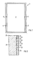
- Fig. 1 generally represents a space heating element, here in the form of a plate, with an electrical resistance layer on its back 2. With 3 and 4 contacting elements are designated, which are glued to the electrical resistance layer or on it in are otherwise attached. 5 and 6 mean the power supply lines.
- FIG. 2 shows a section through a room heating element, which is in the form of a plate with a relief 21 in relief.
- This back 21 has webs 22 or grooves 23.
- an electrically conductive adhesive 24 is applied on the back of this plate, d. H. on the side on which the webs and grooves are located, for example, an electrically conductive adhesive 24 is applied.
- a conductor 27 is provided in a groove 26 adjacent to the edge 25 of the plate.
- the adhesive 24 is an electrical resistance adhesive, i. H. a material that is conductive but is so poorly conductive that the electrical energy introduced into it is converted into thermal energy.
- 31 generally denotes a space heating element which, as shown in FIG. 4, has a plate 41, an adhesive layer 42 and a resistance film 43.
- the resistance film consists of a polyester cover layer 46 connected via the adhesive layer 42 to the side 45 facing away from the visible side 44 of the plate 41, each of which has supply and discharge lines in the form of copper strips 32 to 37 with current supply lines 38 (FIG. 3).
- the resistance film 43 contains three tracks 43a, 43b, 43c made of resistance layer material, but of course it can also be structured more strongly.
- Areas 51 and 52 are located between the tracks 43a and 43b or 43b and 43c.
- the web 43a borders on the area 51 via the conduction band 36.
- the web 43c borders on the area 52 via the conduction band 33, while the web 43b adjoins the areas 51 and 52 on both sides via conduction bands 34 and 35.
- openings 53 through which the adhesive extends from the layer and is connected to the adhesive from the layer 50 on the supporting surface 49.
- the individual conduits can be interconnected in any way. Instead of a single plate 31, three partial plates respectively assigned to the webs 43a, 43b and 43c can also occur.
- the conductive intermediate layer or resistance layer in a training in which it is divided in terms of area while leaving areas not covered by it can be, for. B. a meandering arrangement of the resistance layer or a breakdown of the same into several flat, but electrically interconnected or subsequently to be connected sub-layers in the form of strips, flat pieces or the like. The selection of the appropriate pattern depends on the local conditions and / or the technical requirements.
- a ceramic plate is indicated at 91, on which a resistance layer 92 is applied.
- the application thickness of this resistance coating 92 is determined by means of a suitable measure, e.g. B. sandblasting, electroerosion, brushing od. Dgi. Reduced in thickness, in the illustrated embodiment using a z. B. rotating brush 93, so that the application thickness to the target thickness, as indicated in the area 94, decreases. This also reduces the conductivity of this layer, i. H. the surface resistance increases. In this way, it is possible to fine-tune the resistance value of layer 92.
- a suitable measure e.g. B. sandblasting, electroerosion, brushing od.
- Dgi. Reduced in thickness in the illustrated embodiment using a z. B. rotating brush 93, so that the application thickness to the target thickness, as indicated in the area 94, decreases. This also reduces the conductivity of this layer, i. H. the surface resistance increases. In
Landscapes
- Chemical & Material Sciences (AREA)
- Engineering & Computer Science (AREA)
- Ceramic Engineering (AREA)
- Resistance Heating (AREA)
- Surface Heating Bodies (AREA)
- Central Heating Systems (AREA)
Priority Applications (1)
| Application Number | Priority Date | Filing Date | Title |
|---|---|---|---|
| AT85102230T ATE41845T1 (de) | 1984-02-29 | 1985-02-28 | Raumheizelement, bestehend aus einem mit einer elektrischen widerstandsbeschichtung versehenen keramischen formkoerper und verfahren zu seiner herstellung. |
Applications Claiming Priority (4)
| Application Number | Priority Date | Filing Date | Title |
|---|---|---|---|
| DE3407444 | 1984-02-29 | ||
| DE3407444 | 1984-02-29 | ||
| DE3433667 | 1984-09-13 | ||
| DE19843433667 DE3433667A1 (de) | 1984-02-29 | 1984-09-13 | Keramischer formkoerper |
Publications (2)
| Publication Number | Publication Date |
|---|---|
| EP0158091A1 EP0158091A1 (de) | 1985-10-16 |
| EP0158091B1 true EP0158091B1 (de) | 1989-03-29 |
Family
ID=25818952
Family Applications (1)
| Application Number | Title | Priority Date | Filing Date |
|---|---|---|---|
| EP19850102230 Expired EP0158091B1 (de) | 1984-02-29 | 1985-02-28 | Raumheizelement, bestehend aus einem mit einer elektrischen Widerstandsbeschichtung versehenen keramischen Formkörper und Verfahren zu seiner Herstellung |
Country Status (6)
| Country | Link |
|---|---|
| EP (1) | EP0158091B1 (da) |
| JP (1) | JPS60258891A (da) |
| CA (1) | CA1256480A (da) |
| DK (1) | DK162004C (da) |
| FI (1) | FI83582C (da) |
| NO (1) | NO850814L (da) |
Cited By (1)
| Publication number | Priority date | Publication date | Assignee | Title |
|---|---|---|---|---|
| WO2010092456A3 (en) * | 2009-02-13 | 2011-03-17 | Montanari, Fabrizio | Plant of cellular heating to floor |
Families Citing this family (2)
| Publication number | Priority date | Publication date | Assignee | Title |
|---|---|---|---|---|
| DE3603233A1 (de) * | 1986-02-03 | 1987-08-06 | Buchtal Gmbh | Belag fuer wand-, decken- oder fussbodenbekleidungen |
| WO1997015171A2 (de) * | 1995-10-17 | 1997-04-24 | Magnus Kluge | Elektrische widerstandsheizung zur raumklimatisierung in wohnungen und gebäuden |
Family Cites Families (12)
| Publication number | Priority date | Publication date | Assignee | Title |
|---|---|---|---|---|
| JPS5120043Y2 (da) * | 1971-06-30 | 1976-05-26 | ||
| DE2151626B2 (de) * | 1971-10-16 | 1975-10-23 | Reuter Maschinen- Und Werkzeugbau Gmbh, 2844 Lemfoerde | Verfahren zur Herstellung eines starren, durch Elektrizität aufheizbaren Flächenheizelementes |
| CA1014429A (en) * | 1972-12-20 | 1977-07-26 | Seinosuke Horiki | Calorific device |
| JPS5034768A (da) * | 1973-08-01 | 1975-04-03 | ||
| US3878362A (en) * | 1974-02-15 | 1975-04-15 | Du Pont | Electric heater having laminated structure |
| DE2535622A1 (de) * | 1975-08-09 | 1977-02-17 | Terracom Ets | Heizelement fuer flaechige waermeabgabe |
| JPS5353954U (da) * | 1976-10-08 | 1978-05-09 | ||
| JPS5543751A (en) * | 1978-09-21 | 1980-03-27 | Tokyo Shibaura Electric Co | Plane heating element |
| JPS5568078A (en) * | 1978-11-16 | 1980-05-22 | Nippon Soken | Heating element |
| FR2490056A1 (fr) * | 1980-09-05 | 1982-03-12 | Bonato Mario | Element de surface de chauffage electrique et son procede de fabrication |
| JPS57113576A (en) * | 1980-12-30 | 1982-07-15 | Matsushita Electric Works Ltd | Panel heater |
| DE3311051A1 (de) * | 1983-03-25 | 1984-09-27 | Siemens AG, 1000 Berlin und 8000 München | Flexibles heizelement in bandform, das aus elektrisch leitfaehigen koernchen aus ptc-material und einem organischen isolierenden kunststoff als bindemittel besteht, und verfahren zur herstellung des flexiblen heizelementes |
-
1985
- 1985-02-28 DK DK93785A patent/DK162004C/da not_active IP Right Cessation
- 1985-02-28 NO NO850814A patent/NO850814L/no unknown
- 1985-02-28 JP JP4026985A patent/JPS60258891A/ja active Pending
- 1985-02-28 CA CA000475428A patent/CA1256480A/en not_active Expired
- 1985-02-28 FI FI850821A patent/FI83582C/fi not_active IP Right Cessation
- 1985-02-28 EP EP19850102230 patent/EP0158091B1/de not_active Expired
Cited By (2)
| Publication number | Priority date | Publication date | Assignee | Title |
|---|---|---|---|---|
| WO2010092456A3 (en) * | 2009-02-13 | 2011-03-17 | Montanari, Fabrizio | Plant of cellular heating to floor |
| CN102317693A (zh) * | 2009-02-13 | 2012-01-11 | 法布里齐奥·蒙塔纳里 | 加热地板的单元装置 |
Also Published As
| Publication number | Publication date |
|---|---|
| DK93785A (da) | 1985-08-30 |
| DK162004C (da) | 1992-02-10 |
| FI83582B (fi) | 1991-04-15 |
| CA1256480A (en) | 1989-06-27 |
| FI850821A0 (fi) | 1985-02-28 |
| DK93785D0 (da) | 1985-02-28 |
| JPS60258891A (ja) | 1985-12-20 |
| NO850814L (no) | 1985-08-30 |
| FI850821L (fi) | 1985-08-30 |
| EP0158091A1 (de) | 1985-10-16 |
| FI83582C (fi) | 1991-07-25 |
| DK162004B (da) | 1991-09-02 |
Similar Documents
| Publication | Publication Date | Title |
|---|---|---|
| EP0174604B1 (de) | Wand-, Decken- und/oder Bodenausbildung | |
| DE3502838A1 (de) | Heizelement und verfahren zu dessen herstellung | |
| EP0109019A2 (de) | Flächenheizelement, insbesondere für Verbände oder Heizdecken | |
| DE1966719A1 (de) | Waermespeicherplatte | |
| AT520444B1 (de) | Ausbauplatte mit einem flächigen heizelement | |
| EP3726926B1 (de) | Heizmatte | |
| DE202014009744U1 (de) | Heizanstrich, Heizfarbe, Heizlack, Heizputz, Heizvorrichtung | |
| EP0157179B1 (de) | Mit einer elektrischen Widerstandsbeschichtung versehener flächiger keramischer Formkörper und Verfahren zur Einstellung des Widerstandswertes der Widerstandsbeschichtung | |
| EP0158091B1 (de) | Raumheizelement, bestehend aus einem mit einer elektrischen Widerstandsbeschichtung versehenen keramischen Formkörper und Verfahren zu seiner Herstellung | |
| DE19726689B4 (de) | Elektrisches Heizungssystem zum Beheizen eines Raumes in Wohnungen und Gebäuden durch großflächige Wärmeabgabe | |
| DE3433667A1 (de) | Keramischer formkoerper | |
| EP0357945A1 (de) | Flächiges keramisches Verbundmaterial | |
| DE2949511A1 (de) | Aufrollbare matte fuer elektrische widerstands-fussbodenheizungen | |
| DE3721841C2 (da) | ||
| DE10211721A1 (de) | Heizleiter und Verwendung des Heizleiters | |
| DE3211970C2 (de) | Abdeckplatte für Heizelemente aufweisende Flächenheizungen und Verfahren zu deren Herstellung | |
| DE9102467U1 (de) | Heizvorrichtung | |
| CH442558A (de) | Deckenplatte und Verfahren zur Herstellung derselben | |
| EP3621409A1 (de) | Heizfolie und heizplatte | |
| DE29825103U1 (de) | Elektrische Heizungsanordnung zum Beheizen von Innenräumen mit einer als Heizwiderstand dienenden elektrisch leitfähigen Flächenbeschichtung | |
| DE3934393A1 (de) | Verkleidungs-platte aus stein mit heizleiter | |
| DE2640955C3 (de) | Sonnenenergie absorbierendes Heizrohr | |
| EP0640270B1 (de) | Heizvorrichtung | |
| DE2247025A1 (de) | Flaechenfoermiges heizelement | |
| DE2231854A1 (de) | Elektrisches heizelement |
Legal Events
| Date | Code | Title | Description |
|---|---|---|---|
| PUAI | Public reference made under article 153(3) epc to a published international application that has entered the european phase |
Free format text: ORIGINAL CODE: 0009012 |
|
| AK | Designated contracting states |
Designated state(s): AT BE CH DE FR GB IT LI LU NL SE |
|
| 17P | Request for examination filed |
Effective date: 19850830 |
|
| 17Q | First examination report despatched |
Effective date: 19870319 |
|
| GRAA | (expected) grant |
Free format text: ORIGINAL CODE: 0009210 |
|
| AK | Designated contracting states |
Kind code of ref document: B1 Designated state(s): AT BE CH DE FR GB IT LI LU NL SE |
|
| REF | Corresponds to: |
Ref document number: 41845 Country of ref document: AT Date of ref document: 19890415 Kind code of ref document: T |
|
| ITF | It: translation for a ep patent filed | ||
| REF | Corresponds to: |
Ref document number: 3569183 Country of ref document: DE Date of ref document: 19890503 |
|
| GBT | Gb: translation of ep patent filed (gb section 77(6)(a)/1977) | ||
| ET | Fr: translation filed | ||
| PLBE | No opposition filed within time limit |
Free format text: ORIGINAL CODE: 0009261 |
|
| STAA | Information on the status of an ep patent application or granted ep patent |
Free format text: STATUS: NO OPPOSITION FILED WITHIN TIME LIMIT |
|
| 26N | No opposition filed | ||
| ITTA | It: last paid annual fee | ||
| PGFP | Annual fee paid to national office [announced via postgrant information from national office to epo] |
Ref country code: GB Payment date: 19920213 Year of fee payment: 8 |
|
| PGFP | Annual fee paid to national office [announced via postgrant information from national office to epo] |
Ref country code: FR Payment date: 19920214 Year of fee payment: 8 |
|
| PGFP | Annual fee paid to national office [announced via postgrant information from national office to epo] |
Ref country code: SE Payment date: 19920220 Year of fee payment: 8 |
|
| PGFP | Annual fee paid to national office [announced via postgrant information from national office to epo] |
Ref country code: AT Payment date: 19920224 Year of fee payment: 8 |
|
| PGFP | Annual fee paid to national office [announced via postgrant information from national office to epo] |
Ref country code: LU Payment date: 19920226 Year of fee payment: 8 |
|
| PGFP | Annual fee paid to national office [announced via postgrant information from national office to epo] |
Ref country code: NL Payment date: 19920229 Year of fee payment: 8 |
|
| PGFP | Annual fee paid to national office [announced via postgrant information from national office to epo] |
Ref country code: BE Payment date: 19920304 Year of fee payment: 8 |
|
| PGFP | Annual fee paid to national office [announced via postgrant information from national office to epo] |
Ref country code: CH Payment date: 19920318 Year of fee payment: 8 |
|
| PGFP | Annual fee paid to national office [announced via postgrant information from national office to epo] |
Ref country code: DE Payment date: 19920324 Year of fee payment: 8 |
|
| EPTA | Lu: last paid annual fee | ||
| PG25 | Lapsed in a contracting state [announced via postgrant information from national office to epo] |
Ref country code: LU Free format text: LAPSE BECAUSE OF NON-PAYMENT OF DUE FEES Effective date: 19930228 Ref country code: LI Effective date: 19930228 Ref country code: GB Effective date: 19930228 Ref country code: CH Effective date: 19930228 Ref country code: BE Effective date: 19930228 Ref country code: AT Effective date: 19930228 |
|
| PG25 | Lapsed in a contracting state [announced via postgrant information from national office to epo] |
Ref country code: SE Effective date: 19930301 |
|
| BERE | Be: lapsed |
Owner name: BUCHTAL G.M.B.H. KERAMISCHE BETRIEBE Effective date: 19930228 |
|
| PG25 | Lapsed in a contracting state [announced via postgrant information from national office to epo] |
Ref country code: NL Effective date: 19930901 |
|
| NLV4 | Nl: lapsed or anulled due to non-payment of the annual fee | ||
| GBPC | Gb: european patent ceased through non-payment of renewal fee |
Effective date: 19930228 |
|
| PG25 | Lapsed in a contracting state [announced via postgrant information from national office to epo] |
Ref country code: FR Effective date: 19931029 |
|
| REG | Reference to a national code |
Ref country code: CH Ref legal event code: PL |
|
| PG25 | Lapsed in a contracting state [announced via postgrant information from national office to epo] |
Ref country code: DE Effective date: 19931103 |
|
| REG | Reference to a national code |
Ref country code: FR Ref legal event code: ST |
|
| EUG | Se: european patent has lapsed |
Ref document number: 85102230.1 Effective date: 19931008 |