EP0157236A1 - Accouplement à cisaillement de fluide, notamment pour les boîtes à différentiel pour automobiles - Google Patents
Accouplement à cisaillement de fluide, notamment pour les boîtes à différentiel pour automobiles Download PDFInfo
- Publication number
- EP0157236A1 EP0157236A1 EP85102803A EP85102803A EP0157236A1 EP 0157236 A1 EP0157236 A1 EP 0157236A1 EP 85102803 A EP85102803 A EP 85102803A EP 85102803 A EP85102803 A EP 85102803A EP 0157236 A1 EP0157236 A1 EP 0157236A1
- Authority
- EP
- European Patent Office
- Prior art keywords
- coupling according
- slope
- run
- clutch
- disc
- Prior art date
- Legal status (The legal status is an assumption and is not a legal conclusion. Google has not performed a legal analysis and makes no representation as to the accuracy of the status listed.)
- Granted
Links
- 239000012530 fluid Substances 0.000 title claims abstract description 26
- 230000008878 coupling Effects 0.000 title claims description 31
- 238000010168 coupling process Methods 0.000 title claims description 31
- 238000005859 coupling reaction Methods 0.000 title claims description 31
- 241000446313 Lamella Species 0.000 claims description 7
- 238000005096 rolling process Methods 0.000 claims description 7
- 238000006073 displacement reaction Methods 0.000 claims description 5
- 230000002093 peripheral effect Effects 0.000 claims 1
- 230000000630 rising effect Effects 0.000 claims 1
- 230000000694 effects Effects 0.000 description 4
- 125000006850 spacer group Chemical group 0.000 description 4
- 230000002349 favourable effect Effects 0.000 description 2
- 238000010276 construction Methods 0.000 description 1
- 230000007423 decrease Effects 0.000 description 1
- 238000010586 diagram Methods 0.000 description 1
- 238000005516 engineering process Methods 0.000 description 1
- 229920002545 silicone oil Polymers 0.000 description 1
Images

Classifications
-
- F—MECHANICAL ENGINEERING; LIGHTING; HEATING; WEAPONS; BLASTING
- F16—ENGINEERING ELEMENTS AND UNITS; GENERAL MEASURES FOR PRODUCING AND MAINTAINING EFFECTIVE FUNCTIONING OF MACHINES OR INSTALLATIONS; THERMAL INSULATION IN GENERAL
- F16H—GEARING
- F16H48/00—Differential gearings
- F16H48/20—Arrangements for suppressing or influencing the differential action, e.g. locking devices
- F16H48/26—Arrangements for suppressing or influencing the differential action, e.g. locking devices using fluid action, e.g. viscous clutches
-
- F—MECHANICAL ENGINEERING; LIGHTING; HEATING; WEAPONS; BLASTING
- F16—ENGINEERING ELEMENTS AND UNITS; GENERAL MEASURES FOR PRODUCING AND MAINTAINING EFFECTIVE FUNCTIONING OF MACHINES OR INSTALLATIONS; THERMAL INSULATION IN GENERAL
- F16D—COUPLINGS FOR TRANSMITTING ROTATION; CLUTCHES; BRAKES
- F16D35/00—Fluid clutches in which the clutching is predominantly obtained by fluid adhesion
- F16D35/005—Fluid clutches in which the clutching is predominantly obtained by fluid adhesion with multiple lamellae
Definitions
- the invention relates to a fluid friction clutch, in particular for differential gears of motor vehicles according to the preamble of the main claim.
- Such fluid friction clutches are able to transmit torque or clutch moments as soon as the disk sets rotate against each other.
- the reason for this is the internal friction of the viscous medium.
- the transmissible torque is also reciprocal to the lamella spacing, i.e. it increases with the distance becoming smaller.
- fluid friction clutches are also suitable as differential locks in differential gears of motor vehicles.
- the one set of disks is connected in terms of drive to one output gear, while the other set of disks is either in drive connection with the compensation basket or with the second output gear.
- both differential gears are understood that are installed between the two semi-axles of a drive axle - that is, so-called axle differentials - and those that are provided between two drive axles - combined with a transfer case - of a four-wheel drive.
- the rivers Fluid clutches are either integrated in the construction of the differential or combined as a separate unit with the differential.
- a known fluid friction clutch for use in a motor vehicle is shown in US Pat. No. 4,058,027.
- two such fluid couplings are provided, which are separated from one another by an annular piston.
- one of the clutches also acts as a conventional friction clutch.
- the drive wheels rotate at different speeds, so this causes the aforementioned rotation of the disk sets in the differential.
- Due to the internal friction of the viscous medium, this twisting leads to an increase in temperature, which in turn causes an increase in pressure in the annular chamber.
- the temperature rises the faster the higher the differential speed between the plate sets.
- the increasing pressure moves the ring piston in the axial direction, which pushes the clutch plates together.
- the fluid friction clutch can transmit an ever greater torque, which in reality has the effect of increasingly locking the differential gear.
- the differential gear is gradually blocked as a function of the differential speed via the temperature rise in the annular chamber.
- the known fluid friction clutch has a further disadvantage, which occurs particularly when it is provided in a differential for a four-wheel drive.
- a sol Chen case usually to a difference in the height of the vehicle body on the front and rear axles.
- the differential which in this case is assigned to the transfer case, this in turn leads to a mutual rotation of the plate sets with the temperature rise described and the resulting partial locking of the differential.
- a locking of the differential gear is not desired, such a locking already occurs due to the known fluid friction clutch.
- the result is a drop in efficiency and the risk of damage to the viscous medium due to the permanently elevated temperature.
- the object of the invention is to accomplish in a generic fluid friction clutch the changing of the clutch plate spacing in a different way than by increasing the temperature.
- the fluid friction clutch should not tend to undesired locking.
- the change in the lamella spacing on the one hand brings about the shear forces which occur between the viscous medium and the adjusting disk and the adjacent lamella, and on the other hand the start-up slope.
- the shear forces increase with increasing differential speed. Due to the shear forces, the adjacent clutch disc tries to take the adjusting disc with it when it rotates. This wanders gently due to the start slope, with increasing shear forces towards this clutch plate.
- the clutch plates are pushed together and thus their mutual distance is reduced. As mentioned above, they are able to transmit an ever greater moment.
- the shear forces that build up are also related to the internal friction of the viscous medium. Accordingly, an increase in temperature will also occur here. However, since this temperature rise is not used to adjust the lamellae, the temperature rise can be kept within limits by selecting the medium and the dimensioning of the fluid coupling, so that there is no danger to the medium.
- the starting slope is assigned to the outer or inner body. It only has to be designed in such a way that it rises in the axial direction of the clutch in order to be able to cause the adjusting disk to migrate axially.
- the clutch according to the invention is particularly well suited for the transfer case of a four-wheel drive, in which, as already mentioned, the disk sets of the clutch rotate against each other even when driving straight ahead at a higher speed.
- the shear forces required to move the adjusting disc are determined by the slope of the run-up slope. On the one hand, the shear forces increase as the speed difference between the plate sets increases, and on the other hand as the distance between the adjusting disc and the adjacent clutch plate decreases.
- the shear forces required for this can essentially only be generated by an increasing speed difference, since the The setting disk does not move noticeably at first.
- the speed difference mentioned which occurs when driving straight ahead at high speeds, may still be too small to generate the shear forces necessary to overcome the steeper section.
- the adjusting disk does not move noticeably, and therefore cannot reduce the overall lamella spacing, so that the clutch torque remains small and the efficiency of the drive train does not drop noticeably.
- This effect can be reinforced by a snap connection, which will be described in more detail later.
- the direction of rotation of the individual plate packs is not fixed. Depending on the driving situation, you can turn in either direction. It is therefore advisable to assign at least one run-up slope to each direction of rotation. In order to increase the effect of the arrangement, it is advantageous to provide several bevels for each direction of rotation.
- the run-on slope is assigned to the adjusting disk.
- the chamfer and the adjusting disk can be made in one piece.
- the run-on slope can be supported on a component via a rolling element, for example a ball, which is in turn assigned to the corresponding drive connection in a manner fixed against relative rotation. It is also advantageous if the adjusting disk is pressed against this component with its run-on slope. As a result, perfect rolling or sliding is achieved, on the other hand, the adjusting disk is always pushed back into its initial position when the disk sets come to a standstill.
- Magnetic elements which are expediently used in the adjusting disc, can further support this resetting. By using such elements there is also the advantage that the return spring dim dim overall can be sioned. This has a particularly favorable effect on a return spring which is formed from individual spacer springs which are arranged between the clutch plates.
- the run-up slope can also be provided on a profile disk.
- This profile disc can have bevels on each side.
- one adjusting disk is provided for each side of the profile disk.
- both the profile disk and the adjusting disk are assigned run-on slopes.
- These run-up bevels are then carried out in mirror image and a rolling element expediently rolls again in the cavity formed by them.
- the profile disk is attached to a radial wall.
- the profiled disc is omitted and the run-on slope is formed on a radial wall of the annular chamber. This results in an even more compact structure.
- the clutch plates of a plate set are used as adjusting disks in a further advantageous embodiment.
- the clutch plates sit on a sleeve-like plate carrier, one end face of which is assigned to the run-on slope.
- the adjusting disc moves in the direction of the clutch plate, it must displace the viscous medium.
- the throughput can be controlled or throttled via the diameter size and thus influence the emigration speed of the adjusting disc.
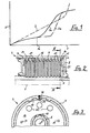
- FIGS. 2 and 3 Such a torque characteristic is obtained with a fluid friction clutch according to FIGS. 2 and 3.
- FIG. 2 only the upper section of the fluid friction clutch 4 adjoining the coupling axis 5 is shown in section. The lower section has been omitted for simplicity.
- the coupling axis 5 is always meant when the subject discussed here is axis or axis direction.
- the fluid friction clutch 4 is provided for a differential gear of a motor vehicle. However, it is not limited to the motor vehicle sector; it can be used in general in drive technology. The parts of the differential gear surrounding the fluid friction clutch 4 are not shown.
- the fluid friction clutch 4 has a closed annular chamber which is formed from a cylindrical inner body 6, a drum-shaped outer body 7 arranged coaxially and rotatably on the cylindrical inner body 6, and radial walls 8 and 9 arranged between the inner body 6 and outer body 7 Radial wall 8 is integrally connected to the outer body 7 and the radial wall 9 is carried out separately from the inner body 6 and the outer body 7.
- the ring chamber is sealed to the outside and contains a viscous medium, which can consist of a silicone oil, for example. The ring chamber is almost completely filled with this medium.
- the annular chamber contains two interlocking plate sets with clutch plates 10 and 11.
- the clutch plates 10 and 11 can be rotated about the clutch axis 5, which is also the common axis of rotation of the inner body 6 and outer body 7.
- the annular clutch plates 10 and 11 are alternately one on the other consequently and at a distance from each other.
- the clutch plates 10 are splined to the outer body 7 in drive connection, while the clutch plates 11 are connected to the drive body via a corresponding toothing.
- the splines of the inner body 6 and the outer body 7 are indicated in Fig. 3 with 12 and 13.
- a sliding member which in FIG. 2 consists of an annular adjusting disk 14 which can be rotated about the coupling axis 5.
- the adjusting disc 14 can be rotated relative to the inner body 6 and, if only within certain limits, the outer body 7.
- the adjusting disc 14 of the last clutch plate 11 of the one clutch set is opposite from each other.
- the adjusting disc 14 is in contact with a component 15, which is connected to the radial wall 8 via an indicated screw connection.
- the component 15 can also be made in one piece with this radial wall 8.
- each radial wall 8, 9 is assigned such an adjusting disk 14; in the further course of the description, however, only that on the radial wall 8 will be considered.
- the explanations apply mutatis mutandis to the other.
- Spacer springs 16 are provided between the individual clutch plates 10 and keep the clutch plates at a distance. In addition or exclusively, such existing springs can also be arranged between the clutch plates 11.
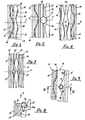
- Fig. 4 shows the annular chamber from above in the area of the adjusting disc 14 in a developed view.
- the cylinder wall of the outer body 7 is removed.
- the structure, part 15, has on one side, which faces the adjusting disc 14 and is substantially perpendicular to the coupling axis, a plurality of bevels 17, 18 distributed around the circumference.
- the arrival Sloping surfaces 17 are assigned to one direction of rotation, the sloping surfaces 18 to the other. Both types of chamfers increase in the axial direction of the coupling axis 5.
- D e actuating disc 14 has on its, the member 15 facing S 'ite a the starting slopes 17, 18 replicated in shape and is pressed thereto by the spacer springs 16 to the Auteil 15th
- the device works in the following manner: In the normal state, that is, if the "clutch plates 10 and 11 do not rotate with respect to one another, the adjusting disk 14 does not rotate with respect to the clutch plate 11. If a situation arises in which the clutch plates rotate with respect to one another, the adjusting disc 14 is first carried along by the outer body 7 via the component 15 and the radial wall 8. As a result, it rotates relative to the clutch disc 11. The viscous medium builds up shear forces between the clutch disc 11 and the adjusting disc 14, which are symbolically indicated in FIG. 4 by the arrows 19. These shear forces now try to take the adjusting disk 14 in the direction of rotation of the clutch disk 11.
- the adjusting disk 14 slides on the run-up slope 18 and is pressed axially in the direction of the clutch plate 11. The distance between these components is reduced and with it all the distances between the individual clutch plates 11 and 10. The smaller the plate spacing increases the transmissible torque between the inner body 6 and the outer body 7 until finally both are quasi rigidly connected to one another. In order to prevent unlimited movement of the adjusting disk 14, it has stops not shown.
- the resetting of the adjusting disk 14 is carried out by the spacer springs 16. From FIG. 3, indicated magnetic elements 20 can be seen, which sit in the adjusting disk 14 and which still support this resetting.
- curve 3 in FIG. 1 shows the torque curve of the fluid coupling according to FIGS. 2 to 4.
- throttle bores 21 FIGGS. 2 and 3 can be provided in the adjusting disk 14.
- the adjustment mechanism is shown in a different way than in Fig. 4.
- 5 shows a ball cage 22 with a ball 23 contained therein, which rolls on the one hand on the run-up slopes 17, 18 and on the other hand acts against the adjusting disk 14.
- the arrangement can also be reversed.
- the bevels 17, 18 would be provided on the adjusting disc 14.
- Corresponding run-on bevels can also be formed both on the adjusting disk 14 and on the component 15.
- the component 15 is replaced by a profile disk 24.
- the profile plate 24 can be arranged anywhere in the plate pack. It is in a drive connection with the outer body 7. On both sides it carries bevels 17 and 18 and accordingly two adjusting disks 14 are assigned to it, which in turn are modeled on the bevels 17, 18.
- FIG. 7 differs from that according to FIG. 6 in that, similar to FIG. 5, balls 23 roll on the bevels 17, 18. It should also be pointed out that more than one profile disk 4 with a corresponding number of adjusting disks according to FIGS. 6 and 7 can be arranged in the disk pack.
- FIG. 9 shows the view in the direction of arrow Z.
- a component 15 corresponding to FIG. 2 carries one or more rolling elements per 25, which are rotatable perpendicular to the coupling axis 5.
- the adjusting disc 14 has a flange 14a which is bent parallel to the coupling axis 5 and faces the component 15 and on the end face of which the run-up bevels 17, 18 are in turn formed.
- the rolling body 5 runs in these run-up slopes.
- Both the designs according to FIGS. 8 and 9 and those according to FIGS. 2 and 4 can be expanded in that a corresponding adjusting device is provided on each radial wall. In this case, however, care must be taken to ensure that the radial wall 9 is also connected to the outer body 7 in terms of drive. Furthermore, it is obvious to construct the whole arrangement in the opposite sense, i.e. that the run-up bevels are not assigned to the outer body 7 but to the inner body 6 and the shear forces are formed between the adjusting disc 14 and a clutch plate 10. In this case, however, insofar as the run-on bevels are provided on the radial walls 8 and 9, they must be connected to the inner body 6 in a rotationally fixed manner.
- FIG. 10 An arrangement in this direction is shown in FIG. 10.
- the displacement member is built up via a sleeve-like plate carrier 26 arranged coaxially to the inner body 10, with which the clutch plates 11 are connected in a rotationally fixed manner.
- These clutch plates 11 form the adjusting disks 14 in the sense of the invention.
- the lamella carrier 26 abuts one end face against a collar 6a (indicated in FIG. 10) by the circle "A".
- the corresponding run-on slope is again formed, which can have a shape corresponding to FIG. 4 or 5, for example.
- a spring 27 presses the plate carrier 26 against the collar 6a.
- This arrangement allows the total clutch torque of all disks of a disk set, here the clutch disks 11, as a control variable for the distance to use. This results in a favorable ratio of clutch torque and friction torque on the starting bevels.
- both the adjusting disk 14 and the component 15 each have corresponding run-on slopes 17, 18.
- Each run-on slope 17, 18 is divided into an initially steeply increasing section 17a, 18a, which then merges into a flat section 17b, 18b.
- Fig. 11 these sections are created by two abutting flat surfaces, in Fig. 12 by different radii.
- a torque curve is achieved, as is designated by 3a in FIG. This follows from the fact that the increase in shear forces and thus the increase in the differential speed of the disk sets must be greater as long as the ball 23 is in the steeper section 17a, 18a of the run-up bevels 17, 18. From about the speed 1a (Fig. 1), the ball 23 merges into the flatter section 17b, 18b.
- curve 3b also shows an even more pronounced course with respect to speed 1a.
- This course is achieved with a snap device as shown in FIG. 3.
- one or more spring-loaded balls 28 are held on the circumference, which engage in corresponding notches 29 in the adjusting disk 14.
- the adjusting disc 14 only moves when the shear forces are so great that they can displace the balls 28 from the notches 29. With an appropriate design, this takes place at speed 1a.
- This snap connection can also be used in connection with the bevels 17, 18 according to FIGS. 11 and 12. Such a snap connection can also be provided on the plate carrier 16 in FIG. 10.
Landscapes
- Engineering & Computer Science (AREA)
- General Engineering & Computer Science (AREA)
- Mechanical Engineering (AREA)
- Retarders (AREA)
- Mechanical Operated Clutches (AREA)
Applications Claiming Priority (2)
| Application Number | Priority Date | Filing Date | Title |
|---|---|---|---|
| DE3408977 | 1984-03-12 | ||
| DE19843408977 DE3408977A1 (de) | 1984-03-12 | 1984-03-12 | Fluessigkeitsreibungskupplung, insbesondere fuer ausgleichsgetriebe von kraftfahrzeugen |
Publications (2)
| Publication Number | Publication Date |
|---|---|
| EP0157236A1 true EP0157236A1 (fr) | 1985-10-09 |
| EP0157236B1 EP0157236B1 (fr) | 1988-09-21 |
Family
ID=6230214
Family Applications (1)
| Application Number | Title | Priority Date | Filing Date |
|---|---|---|---|
| EP85102803A Expired EP0157236B1 (fr) | 1984-03-12 | 1985-03-12 | Accouplement à cisaillement de fluide, notamment pour les boîtes à différentiel pour automobiles |
Country Status (5)
| Country | Link |
|---|---|
| US (1) | US4683998A (fr) |
| EP (1) | EP0157236B1 (fr) |
| JP (1) | JPS61501583A (fr) |
| DE (2) | DE3408977A1 (fr) |
| WO (1) | WO1985004226A1 (fr) |
Cited By (7)
| Publication number | Priority date | Publication date | Assignee | Title |
|---|---|---|---|---|
| EP0225389A1 (fr) * | 1985-01-31 | 1987-06-16 | Tochigifugisangyo Kabushikikaisha | Structure de transmission de puissance par un fluide visqueux |
| EP0479639A1 (fr) * | 1990-10-03 | 1992-04-08 | Glaenzer Spicer | Dispositif d'accouplement à fluide visqueux à caractéristique variable |
| US5127503A (en) * | 1990-07-05 | 1992-07-07 | Steyr-Daimler-Puch Ag | Liquid friction coupling |
| US5310382A (en) * | 1991-04-26 | 1994-05-10 | Glaenzer Spicer | Transmission device with a controlled viscous coupler, in particular for a motor vehicle |
| AT502707A2 (de) * | 2005-11-08 | 2007-05-15 | Gkn Driveline Int Gmbh | Kugelrampenanordnung mit variabler steigung der kugelrillen |
| EP2093450A1 (fr) * | 2008-02-25 | 2009-08-26 | Ausco Products, Inc. | Frein à rampe de balle |
| WO2011036049A1 (fr) * | 2009-09-24 | 2011-03-31 | Schaeffler Technologies Gmbh & Co. Kg | Unité de réglage axial |
Families Citing this family (21)
| Publication number | Priority date | Publication date | Assignee | Title |
|---|---|---|---|---|
| AT384086B (de) * | 1984-09-07 | 1987-09-25 | Steyr Daimler Puch Ag | Fluessigkeitsreibungskupplung |
| US5219053A (en) * | 1985-01-24 | 1993-06-15 | Hybo Science, Inc. | Unidirectional clutch with shell races |
| CA1257106A (fr) * | 1985-02-25 | 1989-07-11 | Masao Teraoka | Dispositif de transmisson d'energie mecanique |
| DE3609419A1 (de) * | 1985-03-30 | 1986-10-09 | Zahnradfabrik Friedrichshafen Ag, 7990 Friedrichshafen | Modulationseinrichtung fuer reibkupplungen |
| AT383877B (de) * | 1985-09-16 | 1987-09-10 | Steyr Daimler Puch Ag | Fluessigkeitsreibungskupplung |
| US5222582A (en) * | 1986-01-22 | 1993-06-29 | Hybo Science, Inc. | Double hyperboloidal-type clutch |
| US5211273A (en) * | 1986-01-22 | 1993-05-18 | Hybo Science, Inc. | Axial thrust clutch/bearing/freewheel |
| JPH0790704B2 (ja) * | 1986-08-20 | 1995-10-04 | 本田技研工業株式会社 | 車両の動力伝達機構 |
| DE3633424C1 (de) * | 1986-10-01 | 1988-02-18 | Deere & Co | Antriebsvorrichtung fuer einen zuschaltbaren Radsatz |
| DE3740570A1 (de) * | 1986-12-04 | 1988-06-09 | Tochigi Fuji Sangyo Kk | Schwungscheibe |
| DE3726641C1 (de) * | 1987-08-11 | 1988-12-29 | Viscodrive Gmbh | Fluessigkeitsreibungskupplung |
| JP2536144B2 (ja) * | 1989-04-07 | 1996-09-18 | トヨタ自動車株式会社 | 動力伝達機構 |
| DE3915959A1 (de) * | 1989-05-18 | 1990-11-22 | Gkn Automotive Ag | Ausgleichsgetriebe |
| JP2540947B2 (ja) * | 1989-07-17 | 1996-10-09 | トヨタ自動車株式会社 | 動力伝達装置 |
| JPH0421A (ja) * | 1990-04-13 | 1992-01-06 | Viscodrive Japan Kk | ビスカスカップリング |
| JP2941077B2 (ja) * | 1991-03-25 | 1999-08-25 | 光洋精工株式会社 | 四輪駆動車用駆動力伝達装置 |
| FR2675866A1 (fr) * | 1991-04-26 | 1992-10-30 | Glaenzer Spicer Sa | Dispositif de transmission a viscocoupleur, notamment pour vehicules automobile. |
| PL170057B1 (pl) * | 1991-05-08 | 1996-10-31 | Btr Eng Australia | Hydrauliczne sprzeglo wodzikowe PL PL PL |
| US5322484A (en) * | 1992-12-22 | 1994-06-21 | Dana Corporation | Locking differential with clutch activated by electrorheological fluid coupling |
| DE4343917C2 (de) * | 1993-12-22 | 1996-03-14 | Gkn Automotive Ag | Viskokupplung |
| DE19824457C2 (de) * | 1998-05-30 | 2000-06-08 | Gkn Viscodrive Gmbh | Wellenkupplung mit Dämpfungsvorrichtung |
Citations (8)
| Publication number | Priority date | Publication date | Assignee | Title |
|---|---|---|---|---|
| DE1235075B (de) * | 1963-05-15 | 1967-02-23 | Eaton Yale & Towne | Regelbare Fluessigkeitsreibungskupplung |
| DE1288361B (de) * | 1960-10-20 | 1969-01-30 | Maybach Mercedes Benz Motorenb | Sicherheits-Reibkupplung fuer eine Lichtanlassmaschine |
| FR2074860A5 (fr) * | 1970-01-27 | 1971-10-08 | Trw Inc | |
| DE2209879A1 (de) * | 1971-03-02 | 1972-09-07 | GKN Transmissions Ltd., Erdington, Birminghamshire (Großbritannien) | Vorrichtung zur Drehmoment-Übertragung |
| DE2225096B2 (de) * | 1972-05-24 | 1976-04-22 | Carl Hurth Maschinen- und Zahnradfabrik, 8000 München | Schaltbare reibungskupplung fuer zahnradgetriebe |
| US4040271A (en) * | 1975-10-22 | 1977-08-09 | Harry Ferguson Limited | Viscous shear couplings |
| US4058027A (en) * | 1976-07-09 | 1977-11-15 | Gkn Transmissions Limited | Control couplings |
| GB2135424A (en) * | 1983-02-15 | 1984-08-30 | Honda Motor Co Ltd | Torsional vibration absorbing device |
Family Cites Families (3)
| Publication number | Priority date | Publication date | Assignee | Title |
|---|---|---|---|---|
| US4238013A (en) * | 1978-05-08 | 1980-12-09 | Eaton Corporation | Contact improver for clutch of a slip limiting differential |
| US4462272A (en) * | 1981-08-19 | 1984-07-31 | Rockwell International Corporation | Limited slip differential |
| US4576264A (en) * | 1983-12-01 | 1986-03-18 | S.O.M., S.P.A. | Servo clutch mechanism, and the drive gear incorporating same |
-
1984
- 1984-03-12 DE DE19843408977 patent/DE3408977A1/de not_active Withdrawn
-
1985
- 1985-03-12 DE DE8585102803T patent/DE3565163D1/de not_active Expired
- 1985-03-12 US US06/799,115 patent/US4683998A/en not_active Expired - Fee Related
- 1985-03-12 WO PCT/EP1985/000097 patent/WO1985004226A1/fr unknown
- 1985-03-12 JP JP60501472A patent/JPS61501583A/ja active Pending
- 1985-03-12 EP EP85102803A patent/EP0157236B1/fr not_active Expired
Patent Citations (8)
| Publication number | Priority date | Publication date | Assignee | Title |
|---|---|---|---|---|
| DE1288361B (de) * | 1960-10-20 | 1969-01-30 | Maybach Mercedes Benz Motorenb | Sicherheits-Reibkupplung fuer eine Lichtanlassmaschine |
| DE1235075B (de) * | 1963-05-15 | 1967-02-23 | Eaton Yale & Towne | Regelbare Fluessigkeitsreibungskupplung |
| FR2074860A5 (fr) * | 1970-01-27 | 1971-10-08 | Trw Inc | |
| DE2209879A1 (de) * | 1971-03-02 | 1972-09-07 | GKN Transmissions Ltd., Erdington, Birminghamshire (Großbritannien) | Vorrichtung zur Drehmoment-Übertragung |
| DE2225096B2 (de) * | 1972-05-24 | 1976-04-22 | Carl Hurth Maschinen- und Zahnradfabrik, 8000 München | Schaltbare reibungskupplung fuer zahnradgetriebe |
| US4040271A (en) * | 1975-10-22 | 1977-08-09 | Harry Ferguson Limited | Viscous shear couplings |
| US4058027A (en) * | 1976-07-09 | 1977-11-15 | Gkn Transmissions Limited | Control couplings |
| GB2135424A (en) * | 1983-02-15 | 1984-08-30 | Honda Motor Co Ltd | Torsional vibration absorbing device |
Cited By (13)
| Publication number | Priority date | Publication date | Assignee | Title |
|---|---|---|---|---|
| EP0225389A1 (fr) * | 1985-01-31 | 1987-06-16 | Tochigifugisangyo Kabushikikaisha | Structure de transmission de puissance par un fluide visqueux |
| EP0225389A4 (fr) * | 1985-01-31 | 1988-09-07 | Tochigi Fuji Sangyo Kk | Structure de transmission de puissance par un fluide visqueux. |
| US5127503A (en) * | 1990-07-05 | 1992-07-07 | Steyr-Daimler-Puch Ag | Liquid friction coupling |
| AT394895B (de) * | 1990-07-05 | 1992-07-10 | Steyr Daimler Puch Ag | Fluessigkeitsreibungskupplung |
| EP0479639A1 (fr) * | 1990-10-03 | 1992-04-08 | Glaenzer Spicer | Dispositif d'accouplement à fluide visqueux à caractéristique variable |
| FR2667663A1 (fr) * | 1990-10-03 | 1992-04-10 | Glaenzer Spicer Sa | Dispositif d'accouplement a fluide visqueux a caracteristique variable. |
| US5310382A (en) * | 1991-04-26 | 1994-05-10 | Glaenzer Spicer | Transmission device with a controlled viscous coupler, in particular for a motor vehicle |
| AT502707A2 (de) * | 2005-11-08 | 2007-05-15 | Gkn Driveline Int Gmbh | Kugelrampenanordnung mit variabler steigung der kugelrillen |
| AT502707A3 (de) * | 2005-11-08 | 2012-11-15 | Gkn Driveline Int Gmbh | Kugelrampenanordnung mit variabler steigung der kugelrillen |
| AT502707B1 (de) * | 2005-11-08 | 2017-07-15 | Gkn Driveline Int Gmbh | Kugelrampenanordnung mit variabler steigung der kugelrillen |
| EP2093450A1 (fr) * | 2008-02-25 | 2009-08-26 | Ausco Products, Inc. | Frein à rampe de balle |
| US8235183B2 (en) | 2008-02-25 | 2012-08-07 | Ausco Products, Inc. | Ball ramp brake |
| WO2011036049A1 (fr) * | 2009-09-24 | 2011-03-31 | Schaeffler Technologies Gmbh & Co. Kg | Unité de réglage axial |
Also Published As
| Publication number | Publication date |
|---|---|
| DE3565163D1 (en) | 1988-10-27 |
| DE3408977A1 (de) | 1985-09-12 |
| US4683998A (en) | 1987-08-04 |
| JPS61501583A (ja) | 1986-07-31 |
| WO1985004226A1 (fr) | 1985-09-26 |
| EP0157236B1 (fr) | 1988-09-21 |
Similar Documents
| Publication | Publication Date | Title |
|---|---|---|
| EP0157236B1 (fr) | Accouplement à cisaillement de fluide, notamment pour les boîtes à différentiel pour automobiles | |
| DE102005061268B4 (de) | Reibungskupplung mit Aktuator und Tellerfeder | |
| DE3915959C2 (fr) | ||
| DE102005053555B3 (de) | Kugelrampenanordnung mit variabler Steigung der Kugelrillen | |
| DE69714183T2 (de) | Sperrdifferential mit Reibkupplungselementen | |
| DE102008063904B4 (de) | Antriebsanordnung | |
| EP0264579B1 (fr) | Transmission différentielle verrouillable | |
| DE69922304T2 (de) | Bremseinrichtung ohne Rückwärtsgang für einen Stellantrieb eines Flugzeuges | |
| DE3529234C2 (fr) | ||
| DE10252974A1 (de) | Einrückmechanismus mit zweistufigem Rampenwinkel | |
| DE102006001334B3 (de) | Getriebeanordnung zur variablen Drehmomentverteilung | |
| DE4327519C2 (de) | Vorrichtung zur Steuerung einer Kupplung | |
| DE3909112A1 (de) | Ausgleichsgetriebe | |
| EP0131881B1 (fr) | Accouplement élastique amortissant les variations de couple entre deux arbres rotatifs | |
| DD294764A5 (de) | Ausgleichsgetriebe | |
| DE4111269C1 (fr) | ||
| DE102013220531A1 (de) | Reibschaltelement | |
| DE3726641C1 (de) | Fluessigkeitsreibungskupplung | |
| DE69205468T2 (de) | Anordnung zur Drehmomentübertragung eines Vierradgetriebenen Fahrzeuges. | |
| DE3630974C2 (fr) | ||
| DE102014214297A1 (de) | Kupplungsanordnung | |
| DE19918411A1 (de) | Steuerbare Viscokupplung | |
| WO2010089009A1 (fr) | Système de transmission de couple de rotation | |
| EP0332608B1 (fr) | Accouplement à frottement visqueux et son application | |
| DE3402917C1 (de) | Differentialgetriebe mit einer reibschlüssigen Sperrkupplung, die durch eine von Ausgleichsbewegungen abhängige selbsttätige Steuerkupplung betätigbar ist |
Legal Events
| Date | Code | Title | Description |
|---|---|---|---|
| PUAI | Public reference made under article 153(3) epc to a published international application that has entered the european phase |
Free format text: ORIGINAL CODE: 0009012 |
|
| AK | Designated contracting states |
Designated state(s): DE FR GB IT SE |
|
| 17P | Request for examination filed |
Effective date: 19850910 |
|
| 17Q | First examination report despatched |
Effective date: 19860723 |
|
| D17Q | First examination report despatched (deleted) | ||
| GRAA | (expected) grant |
Free format text: ORIGINAL CODE: 0009210 |
|
| AK | Designated contracting states |
Kind code of ref document: B1 Designated state(s): DE FR GB IT SE |
|
| REF | Corresponds to: |
Ref document number: 3565163 Country of ref document: DE Date of ref document: 19881027 |
|
| ET | Fr: translation filed | ||
| ITF | It: translation for a ep patent filed | ||
| GBT | Gb: translation of ep patent filed (gb section 77(6)(a)/1977) | ||
| PLBE | No opposition filed within time limit |
Free format text: ORIGINAL CODE: 0009261 |
|
| STAA | Information on the status of an ep patent application or granted ep patent |
Free format text: STATUS: NO OPPOSITION FILED WITHIN TIME LIMIT |
|
| 26N | No opposition filed | ||
| PGFP | Annual fee paid to national office [announced via postgrant information from national office to epo] |
Ref country code: SE Payment date: 19910227 Year of fee payment: 7 |
|
| PGFP | Annual fee paid to national office [announced via postgrant information from national office to epo] |
Ref country code: GB Payment date: 19910308 Year of fee payment: 7 |
|
| PGFP | Annual fee paid to national office [announced via postgrant information from national office to epo] |
Ref country code: DE Payment date: 19910327 Year of fee payment: 7 |
|
| PGFP | Annual fee paid to national office [announced via postgrant information from national office to epo] |
Ref country code: FR Payment date: 19910329 Year of fee payment: 7 |
|
| ITTA | It: last paid annual fee | ||
| PG25 | Lapsed in a contracting state [announced via postgrant information from national office to epo] |
Ref country code: GB Effective date: 19920312 |
|
| PG25 | Lapsed in a contracting state [announced via postgrant information from national office to epo] |
Ref country code: SE Effective date: 19920313 |
|
| GBPC | Gb: european patent ceased through non-payment of renewal fee | ||
| PG25 | Lapsed in a contracting state [announced via postgrant information from national office to epo] |
Ref country code: FR Effective date: 19921130 |
|
| PG25 | Lapsed in a contracting state [announced via postgrant information from national office to epo] |
Ref country code: DE Effective date: 19921201 |
|
| REG | Reference to a national code |
Ref country code: FR Ref legal event code: ST |
|
| EUG | Se: european patent has lapsed |
Ref document number: 85102803.5 Effective date: 19921005 |