EP0156336B1 - Nachrichtenübertragungssystem - Google Patents
Nachrichtenübertragungssystem Download PDFInfo
- Publication number
- EP0156336B1 EP0156336B1 EP19850103449 EP85103449A EP0156336B1 EP 0156336 B1 EP0156336 B1 EP 0156336B1 EP 19850103449 EP19850103449 EP 19850103449 EP 85103449 A EP85103449 A EP 85103449A EP 0156336 B1 EP0156336 B1 EP 0156336B1
- Authority
- EP
- European Patent Office
- Prior art keywords
- control
- stations
- base stations
- station
- communication system
- Prior art date
- Legal status (The legal status is an assumption and is not a legal conclusion. Google has not performed a legal analysis and makes no representation as to the accuracy of the status listed.)
- Expired - Lifetime
Links
- 230000005540 biological transmission Effects 0.000 title claims abstract description 41
- 238000004891 communication Methods 0.000 claims abstract description 18
- 238000000034 method Methods 0.000 claims description 2
- 238000010586 diagram Methods 0.000 description 2
- 238000011161 development Methods 0.000 description 1
- 230000018109 developmental process Effects 0.000 description 1
- 230000007257 malfunction Effects 0.000 description 1
- 238000012544 monitoring process Methods 0.000 description 1
- 230000003287 optical effect Effects 0.000 description 1
- 238000012545 processing Methods 0.000 description 1
Images

Classifications
-
- H—ELECTRICITY
- H04—ELECTRIC COMMUNICATION TECHNIQUE
- H04W—WIRELESS COMMUNICATION NETWORKS
- H04W24/00—Supervisory, monitoring or testing arrangements
- H04W24/04—Arrangements for maintaining operational condition
-
- H—ELECTRICITY
- H04—ELECTRIC COMMUNICATION TECHNIQUE
- H04W—WIRELESS COMMUNICATION NETWORKS
- H04W84/00—Network topologies
- H04W84/02—Hierarchically pre-organised networks, e.g. paging networks, cellular networks, WLAN [Wireless Local Area Network] or WLL [Wireless Local Loop]
- H04W84/04—Large scale networks; Deep hierarchical networks
- H04W84/042—Public Land Mobile systems, e.g. cellular systems
-
- H—ELECTRICITY
- H04—ELECTRIC COMMUNICATION TECHNIQUE
- H04W—WIRELESS COMMUNICATION NETWORKS
- H04W88/00—Devices specially adapted for wireless communication networks, e.g. terminals, base stations or access point devices
- H04W88/12—Access point controller devices
-
- H—ELECTRICITY
- H04—ELECTRIC COMMUNICATION TECHNIQUE
- H04W—WIRELESS COMMUNICATION NETWORKS
- H04W92/00—Interfaces specially adapted for wireless communication networks
- H04W92/04—Interfaces between hierarchically different network devices
- H04W92/14—Interfaces between hierarchically different network devices between access point controllers and backbone network device
Definitions
- the invention relates to a communication system according to the preamble of claim 1.
- a mobile telephone system with its essential features is known.
- 1 on page 1451 in particular shows an arrangement in which a public network (PSTN) is connected to a plurality of switching centers MSC.
- PSTN public network
- MSC Mobile Service Switching Center
- Base stations BS are connected to these switching centers MSC.
- the traffic to the mobile stations MS takes place via the base stations BS.
- the three switching centers MSC shown in FIG. 1 are connected to one another via analog and digital data channels.
- the arrangement described has the disadvantage that the connections between the switching centers MSC are not used optimally.
- the object of the invention is therefore to create a message transmission system in which the connections existing between the exchanges are used in an optimal manner.
- the section of the new message transmission system shown in FIG. 1 contains two control centers LS, each of which is provided with a gateway U to a telephone network.
- the control centers LS are connected by two transmission paths, called connecting lines.
- a ring-shaped transmission path, called a ring line is connected to each control center LS.
- These transmission paths are implemented using optical communication cables.
- Other transmission media for example microwave links or cables, can also be used.
- Several base stations FS are arranged in succession on each transmission path. You can communicate with one or more MS mobile stations by radio. The radio traffic is carried out in the manner described in DE-OS 31 18 018.
- a PCM 30 system is used separately on each transmission path for each transmission direction. This system is known from the journal Electrical News, Volume 48 No. 1 and 2, 1973 pp 72-83. It contains 32 time-division multiplex channels, 30 of which are intended for the transmission of message signals and the other two channels are control channels.
- Each control center LS has several devices E, to each of which one end of a transmission path is connected.
- Each base station FS is assigned to a control center LS.
- the transmission of the messages and control signals from and to a specific base station FS takes place via one and the same device E of the responsible control center LS, regardless of whether the base station FS is arranged in the course of a connection or ring line.
- the message traffic is evenly distributed over all base stations FS of the ring lines, the four base stations FS of a first facility E in the responsible control center LS and the remaining four base stations FS are arranged on the right part of the ring lines assigned to other device E of the same control center LS.
- each base station FS Since each base station FS only reads and processes the signals intended for it from all signals transmitted on all channels of the PCM 30 systems, and forwards all other signals to the adjacent base station FS, a different assignment is also possible.
- the existing time-division multiplex channels can be used twice as follows on each transmission path.
- One PCM 30 system of a transmission path transmits on the right part of the ring line the signals determined by the first device E for the four fixed stations FS arranged there. On the left part, the same channels are occupied with the signals to be transmitted from the base stations there to the other facility E of the same control center LS.
- the other PCM 30 system works accordingly in the other transmission direction.
- the connecting lines there the two devices E at the ends of the connecting lines belong to two different control centers LS.
- the time-division multiplex channels occupied by such signals are only used once.
- the dual-use channels that is to say those for message transmission between a base station FS and its responsible control center LS, are small channel numbers, ie. H. channel number 1 to i, beginning with channel number 1, and for easy-to-use channels large channel numbers i + 1 to k, beginning with channel number k.
- channels 1 to 5 are used twice
- channels 6 - 10 are used for message transmission between one control center LS and one or more base stations FS assigned to them
- channels 11 - 23 are free
- channels 24 - 30 are used for direct message traffic between the two control centers LS.
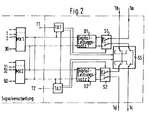
- the digital line set D1 is connected to a first clock / alarm circuit TA1 and two multiplexers / demultiplexers, called Muldexer, MX1 and MX2.
- the digital line set D2 is connected to a second clock / alarm circuit TA2 and the Muldexern MX1 and MX2.
- the clock / alarm circuit TA1 is connected to the switches S1 and SS
- the clock / alarm circuit TA2 is connected to the switches S2 and SS and both clock / alarm circuits are connected to one another.
- the switches S1, S2 and SS assume the position shown in FIG. 2.
- the digital line set D1 reads the signals intended for it from the signals arriving at 1a and forwards them to the mobile stations via the Muldexer MX1 or MX2 and other components not shown.
- the other signals go to the next base station via 1c.
- the signals originating from the mobile stations are fed into line 1b via the Muldexer MX1 or MX2 and the digital line set 2.
- the clock / alarm circuit TA1 causes the switch of the switch S1 to separate the digital line set D1 from the line 1a, c, and sets a corresponding message on the control channel via the clock / alarm circuit TA2 and the digital line set D2 Control center. As described above, this switches the switch SS and assigns the base station and, if necessary, the neighboring base stations to the other control center, or, in the case of ring lines, to the other device E at the other end of the ring line.
- the digital line set D2 now transmits messages and control signals intended for this base station in both directions.
- the two control channels of each PCM 30 system serve to supply clocks to the base stations FS and to transmit all the necessary control signals. These include, in particular, signals for distributing the time-division multiplex channels to the mobile stations MS, for setting up and clearing down the message connection between a mobile station MS and a control center LS, for forwarding the mobile station from one base station to the adjacent base station without interrupting the message connection, for transmitting busy signals, etc. and to control the message transmission system in normal and malfunction cases.
- the clock / alarm units TA1 and TA2 take out of monitoring of the respectively assigned digital line set D1 or D2 and the processing of alarm signals further functions, in particular the clock synchronization or the clock supply of the base station
Landscapes
- Engineering & Computer Science (AREA)
- Computer Networks & Wireless Communication (AREA)
- Signal Processing (AREA)
- Mobile Radio Communication Systems (AREA)
- Radio Relay Systems (AREA)
- Time-Division Multiplex Systems (AREA)
Priority Applications (1)
| Application Number | Priority Date | Filing Date | Title |
|---|---|---|---|
| AT85103449T ATE72373T1 (de) | 1984-03-24 | 1985-03-23 | Nachrichtenuebertragungssystem. |
Applications Claiming Priority (2)
| Application Number | Priority Date | Filing Date | Title |
|---|---|---|---|
| DE3411013A DE3411013A1 (de) | 1984-03-24 | 1984-03-24 | Nachrichtenuebertragungssystem |
| DE3411013 | 1984-03-24 |
Publications (3)
| Publication Number | Publication Date |
|---|---|
| EP0156336A2 EP0156336A2 (de) | 1985-10-02 |
| EP0156336A3 EP0156336A3 (en) | 1988-03-23 |
| EP0156336B1 true EP0156336B1 (de) | 1992-01-29 |
Family
ID=6231596
Family Applications (1)
| Application Number | Title | Priority Date | Filing Date |
|---|---|---|---|
| EP19850103449 Expired - Lifetime EP0156336B1 (de) | 1984-03-24 | 1985-03-23 | Nachrichtenübertragungssystem |
Country Status (9)
| Country | Link |
|---|---|
| US (1) | US4686671A (enExample) |
| EP (1) | EP0156336B1 (enExample) |
| JP (1) | JPS611126A (enExample) |
| AT (1) | ATE72373T1 (enExample) |
| AU (1) | AU578271B2 (enExample) |
| CA (1) | CA1232329A (enExample) |
| DE (2) | DE3411013A1 (enExample) |
| ES (1) | ES8704064A1 (enExample) |
| GR (1) | GR850724B (enExample) |
Families Citing this family (23)
| Publication number | Priority date | Publication date | Assignee | Title |
|---|---|---|---|---|
| US5682256A (en) * | 1988-11-11 | 1997-10-28 | British Telecommunications Public Limited Company | Communications system |
| GB8826476D0 (en) * | 1988-11-11 | 1988-12-14 | British Telecomm | Communications system |
| AU634234B2 (en) | 1989-05-30 | 1993-02-18 | Motorola, Inc. | Method of establishing communication between independent communication systems |
| US5084869A (en) * | 1990-01-31 | 1992-01-28 | At&T Bell Laboratories | Base station for mobile radio telecommunications systems |
| US5384826A (en) * | 1990-10-01 | 1995-01-24 | At&T Bell Laboratories | Distributed packetized switching cellular radio telephone communication system with handoff |
| US5371780A (en) * | 1990-10-01 | 1994-12-06 | At&T Corp. | Communications resource assignment in a wireless telecommunications system |
| CA2052466C (en) * | 1990-10-02 | 2001-05-08 | Masayuki Sakamoto | Method of handover and route diversity in mobile radio communication |
| JPH04142820A (ja) * | 1990-10-04 | 1992-05-15 | Nippon Telegr & Teleph Corp <Ntt> | 移動通信における基地局送信方式 |
| US5305467A (en) * | 1990-12-03 | 1994-04-19 | Ericsson Ge Mobile Communications Inc. | Local area network for flexible digital communications within and between RF base stations |
| IT1251119B (it) * | 1991-07-26 | 1995-05-04 | Rete radiomobile isofrequenziale con dorsale di collegamento realizzata mediante un sistema di drop/insert. | |
| FI88991C (fi) * | 1991-10-03 | 1993-07-26 | Nokia Telecommunications Oy | Allokeringsfoerfarande foer radiokanaler |
| US5422885A (en) * | 1992-06-01 | 1995-06-06 | Motorola, Inc. | Contention free local area network |
| FI108100B (fi) * | 1993-06-23 | 2001-11-15 | Nokia Networks Oy | Tiedonsiirtomenetelmä ja tiedonsiirtojärjestelmä solukkoradioverkossa |
| AU708751B2 (en) * | 1994-05-27 | 1999-08-12 | Curtin University Of Technology | Cellular communications network |
| AUPM593694A0 (en) * | 1994-05-27 | 1994-06-23 | Curtin University Of Technology | Underground microcellular communications network |
| JP3231210B2 (ja) * | 1995-03-03 | 2001-11-19 | 株式会社日立製作所 | 無線通信システム |
| KR20000005099A (ko) | 1996-03-26 | 2000-01-25 | 내쉬 로저 윌리엄 | 부가적인 통신경로를 포함하는 셀룰러 전화시스템 |
| DE19827027C2 (de) * | 1998-06-17 | 2000-05-18 | Siemens Ag | Basisstation |
| EP0982956A1 (en) * | 1998-08-25 | 2000-03-01 | Lucent Technologies Inc. | Base station equipment for a mobile cellular telecommunications network |
| EP1049344A1 (en) * | 1999-04-27 | 2000-11-02 | Lucent Technologies Inc. | Base station equipment for a mobile telecommunications network |
| US6628676B1 (en) * | 1999-06-21 | 2003-09-30 | Ericsson Inc. | Systems and methods for communicating messages among cascaded devices by bit shifting |
| AU2001280808A1 (en) * | 2000-08-15 | 2002-02-25 | Telefonaktiebolaget Lm Ericsson | A method to utilize ring topology in communication channels linking cascaded radio heads |
| US20030021251A1 (en) * | 2001-07-30 | 2003-01-30 | Ramin Moshiri-Tafreshi | Self-healing wireless communication systems |
Family Cites Families (10)
| Publication number | Priority date | Publication date | Assignee | Title |
|---|---|---|---|---|
| GB1229149A (enExample) * | 1969-07-28 | 1971-04-21 | ||
| US3731002A (en) * | 1970-10-08 | 1973-05-01 | Bell Telephone Labor Inc | Interconnected loop data block transmission system |
| DE2931084C3 (de) * | 1979-07-31 | 1982-03-11 | Siemens AG, 1000 Berlin und 8000 München | Funksystem |
| FR2472898B1 (fr) * | 1979-12-27 | 1987-01-09 | Jeumont Schneider | Reseau de transmission en boucle double |
| FR2505124A1 (en) * | 1981-04-30 | 1982-11-05 | Jeumont Schneider | Telephone subscriber linking circuit - includes controlled series loops connecting subscribers each provided with auto-commutator |
| JPS58175335A (ja) * | 1982-04-07 | 1983-10-14 | Hitachi Ltd | ル−プ式デ−タ伝送システムのル−プバツク制御方法 |
| JPS5940739A (ja) * | 1982-08-30 | 1984-03-06 | Fujitsu Ltd | ル−プパツク制御方式 |
| EP0112425B1 (fr) * | 1982-12-28 | 1987-08-19 | International Business Machines Corporation | Réseau de connexion temps-espace-temps utilisant une liaison en boucle fermée |
| FR2540694B1 (fr) * | 1983-02-07 | 1988-05-13 | Trt Telecom Radio Electr | Systeme de telecommunication en boucle a multiplex temporel comportant une premiere et une deuxieme lignes de transmission |
| GB2143403B (en) * | 1983-07-15 | 1986-10-29 | Standard Telephones Cables Ltd | Telecommunication exchange |
-
1984
- 1984-03-24 DE DE3411013A patent/DE3411013A1/de not_active Withdrawn
-
1985
- 1985-03-14 AU AU39845/85A patent/AU578271B2/en not_active Ceased
- 1985-03-18 CA CA000476730A patent/CA1232329A/en not_active Expired
- 1985-03-21 GR GR850724A patent/GR850724B/el unknown
- 1985-03-22 ES ES541506A patent/ES8704064A1/es not_active Expired
- 1985-03-22 US US06/715,146 patent/US4686671A/en not_active Expired - Fee Related
- 1985-03-23 EP EP19850103449 patent/EP0156336B1/de not_active Expired - Lifetime
- 1985-03-23 DE DE8585103449T patent/DE3585292D1/de not_active Expired - Lifetime
- 1985-03-23 AT AT85103449T patent/ATE72373T1/de not_active IP Right Cessation
- 1985-03-25 JP JP60058621A patent/JPS611126A/ja active Pending
Also Published As
| Publication number | Publication date |
|---|---|
| ATE72373T1 (de) | 1992-02-15 |
| GR850724B (enExample) | 1985-07-19 |
| ES8704064A1 (es) | 1987-02-16 |
| ES541506A0 (es) | 1987-02-16 |
| DE3585292D1 (de) | 1992-03-12 |
| US4686671A (en) | 1987-08-11 |
| CA1232329A (en) | 1988-02-02 |
| JPS611126A (ja) | 1986-01-07 |
| EP0156336A3 (en) | 1988-03-23 |
| EP0156336A2 (de) | 1985-10-02 |
| DE3411013A1 (de) | 1985-09-26 |
| AU578271B2 (en) | 1988-10-20 |
| AU3984585A (en) | 1985-09-26 |
Similar Documents
| Publication | Publication Date | Title |
|---|---|---|
| EP0156336B1 (de) | Nachrichtenübertragungssystem | |
| DE69433624T2 (de) | Basisstation in einer zellularen funkanordnung | |
| DE69222345T2 (de) | Digitales Zellularvermittlungssystem mit Mitteln zur Gewährleistung ununterbrochener Datentransparenz während des Weiterreichens einer Verbindung | |
| DE69025724T2 (de) | Zugriffssendegerät für synchrone Transmissionsleitung mit hoher Geschwindigkeit | |
| DE2903650A1 (de) | Telefonvermittlungssystem mit zeitmultiplexverfahren | |
| DE69228275T2 (de) | Umlegen von Leitungen in einem digitalen Übertragungssystem-SLC | |
| EP0773693A2 (de) | Netzanpassungszentrale für ein Mobilfunknetz | |
| EP0281888B1 (de) | Schaltungsanordnung für Teilnehmeranschlussschaltungen einer digitalen Zeitmultiplex-Fernmelde-Vermittlungsstelle | |
| DE2619391B2 (de) | Nachrichtensystem mit Vielfachzugriff und dezentraler Vermittlung | |
| DE4422805C1 (de) | Verfahren zum Laden von Software in Kommunikationssystemen mit nichtredundaten, dezentralen Einrichtungen | |
| DE4207675C1 (enExample) | ||
| EP0162994A1 (de) | Kommunikationsnetz und dessen Verwendung | |
| EP0475135B1 (de) | Übertragungssystem für Zubringernetze in Kommunikationsnetzen | |
| DE2808666A1 (de) | Dezentral gesteuerte fernsprechanlage | |
| DE3016546C2 (enExample) | ||
| EP0016396B1 (de) | Koppelfeld mit Verbindungswegeumkehr, insbesondere für Fernsprechvermittlungsanlagen | |
| EP0023297B1 (de) | Digital-Fernmeldesystem | |
| EP0024725B1 (de) | Schaltungsanordnung zum Anschluss von Abfrageplätzen an eine mehrstufige, zeitmultiplexe Fernsprechvermittlungsanlage | |
| EP0676906B1 (de) | Verfahren zur Übertragung von Sprach- und Servicesignalen und Kommunikationssystem | |
| DE3151081C2 (de) | Verfahren und Anordnung zur Verbindungsherstellung in einer Fernmeldeanlage | |
| DE2148411C3 (de) | Verfahren zum Suchen freier Verbindungswege in einem Fernmeldenetz | |
| DE3037419C2 (de) | Schaltungsanordnung zum Überwachen unzulässiger Verbindungen in einem Koppelfeld für Vermittlungsanlagen, insbesondere Fernsprechvermittlungsanlagen | |
| DE4315022C1 (de) | Digitales Zeitmultiplex-Vermittlungssystem | |
| DE3609890C2 (enExample) | ||
| EP0539761B1 (de) | Verfahren und Anordnung zum Feststellen eines gestörten, in einem Kanalbündel enthaltenen Kanals |
Legal Events
| Date | Code | Title | Description |
|---|---|---|---|
| PUAI | Public reference made under article 153(3) epc to a published international application that has entered the european phase |
Free format text: ORIGINAL CODE: 0009012 |
|
| AK | Designated contracting states |
Designated state(s): AT BE CH DE FR GB IT LI LU NL SE |
|
| PUAL | Search report despatched |
Free format text: ORIGINAL CODE: 0009013 |
|
| AK | Designated contracting states |
Kind code of ref document: A3 Designated state(s): AT BE CH DE FR GB IT LI LU NL SE |
|
| 17P | Request for examination filed |
Effective date: 19880822 |
|
| 17Q | First examination report despatched |
Effective date: 19900827 |
|
| ITF | It: translation for a ep patent filed | ||
| GRAA | (expected) grant |
Free format text: ORIGINAL CODE: 0009210 |
|
| AK | Designated contracting states |
Kind code of ref document: B1 Designated state(s): AT BE CH DE FR GB IT LI LU NL SE |
|
| REF | Corresponds to: |
Ref document number: 72373 Country of ref document: AT Date of ref document: 19920215 Kind code of ref document: T |
|
| PGFP | Annual fee paid to national office [announced via postgrant information from national office to epo] |
Ref country code: LU Payment date: 19920225 Year of fee payment: 8 |
|
| GBT | Gb: translation of ep patent filed (gb section 77(6)(a)/1977) | ||
| REF | Corresponds to: |
Ref document number: 3585292 Country of ref document: DE Date of ref document: 19920312 |
|
| ET | Fr: translation filed | ||
| EPTA | Lu: last paid annual fee | ||
| RAP4 | Party data changed (patent owner data changed or rights of a patent transferred) |
Owner name: ALCATEL SEL AKTIENGESELLSCHAFT |
|
| PLBE | No opposition filed within time limit |
Free format text: ORIGINAL CODE: 0009261 |
|
| STAA | Information on the status of an ep patent application or granted ep patent |
Free format text: STATUS: NO OPPOSITION FILED WITHIN TIME LIMIT |
|
| PGFP | Annual fee paid to national office [announced via postgrant information from national office to epo] |
Ref country code: FR Payment date: 19921230 Year of fee payment: 9 |
|
| 26N | No opposition filed | ||
| PGFP | Annual fee paid to national office [announced via postgrant information from national office to epo] |
Ref country code: GB Payment date: 19930225 Year of fee payment: 9 |
|
| PG25 | Lapsed in a contracting state [announced via postgrant information from national office to epo] |
Ref country code: LU Free format text: LAPSE BECAUSE OF NON-PAYMENT OF DUE FEES Effective date: 19930323 |
|
| PGFP | Annual fee paid to national office [announced via postgrant information from national office to epo] |
Ref country code: SE Payment date: 19930324 Year of fee payment: 9 |
|
| PGFP | Annual fee paid to national office [announced via postgrant information from national office to epo] |
Ref country code: AT Payment date: 19930325 Year of fee payment: 9 |
|
| PGFP | Annual fee paid to national office [announced via postgrant information from national office to epo] |
Ref country code: NL Payment date: 19930331 Year of fee payment: 9 |
|
| PGFP | Annual fee paid to national office [announced via postgrant information from national office to epo] |
Ref country code: BE Payment date: 19930414 Year of fee payment: 9 |
|
| ITPR | It: changes in ownership of a european patent |
Owner name: CAMBIO RAGIONE SOCIALE;ALCATEL SEL AKTIENGESELLSCH |
|
| PGFP | Annual fee paid to national office [announced via postgrant information from national office to epo] |
Ref country code: DE Payment date: 19930512 Year of fee payment: 9 |
|
| PGFP | Annual fee paid to national office [announced via postgrant information from national office to epo] |
Ref country code: CH Payment date: 19930617 Year of fee payment: 9 |
|
| PG25 | Lapsed in a contracting state [announced via postgrant information from national office to epo] |
Ref country code: GB Effective date: 19940323 Ref country code: AT Effective date: 19940323 |
|
| PG25 | Lapsed in a contracting state [announced via postgrant information from national office to epo] |
Ref country code: SE Free format text: LAPSE BECAUSE OF NON-PAYMENT OF DUE FEES Effective date: 19940324 |
|
| PG25 | Lapsed in a contracting state [announced via postgrant information from national office to epo] |
Ref country code: LI Effective date: 19940331 Ref country code: CH Effective date: 19940331 Ref country code: BE Effective date: 19940331 |
|
| BERE | Be: lapsed |
Owner name: STANDARD ELEKTRIK LORENZ A.G. Effective date: 19940331 |
|
| PG25 | Lapsed in a contracting state [announced via postgrant information from national office to epo] |
Ref country code: NL Effective date: 19941001 |
|
| NLV4 | Nl: lapsed or anulled due to non-payment of the annual fee | ||
| GBPC | Gb: european patent ceased through non-payment of renewal fee |
Effective date: 19940323 |
|
| PG25 | Lapsed in a contracting state [announced via postgrant information from national office to epo] |
Ref country code: FR Effective date: 19941130 |
|
| REG | Reference to a national code |
Ref country code: CH Ref legal event code: PL |
|
| PG25 | Lapsed in a contracting state [announced via postgrant information from national office to epo] |
Ref country code: DE Effective date: 19941201 |
|
| REG | Reference to a national code |
Ref country code: FR Ref legal event code: ST |
|
| EUG | Se: european patent has lapsed |
Ref document number: 85103449.6 Effective date: 19941010 |