EP0156336B1 - Information transmission system - Google Patents
Information transmission system Download PDFInfo
- Publication number
- EP0156336B1 EP0156336B1 EP19850103449 EP85103449A EP0156336B1 EP 0156336 B1 EP0156336 B1 EP 0156336B1 EP 19850103449 EP19850103449 EP 19850103449 EP 85103449 A EP85103449 A EP 85103449A EP 0156336 B1 EP0156336 B1 EP 0156336B1
- Authority
- EP
- European Patent Office
- Prior art keywords
- control
- stations
- base stations
- station
- communication system
- Prior art date
- Legal status (The legal status is an assumption and is not a legal conclusion. Google has not performed a legal analysis and makes no representation as to the accuracy of the status listed.)
- Expired - Lifetime
Links
Images

Classifications
-
- H—ELECTRICITY
- H04—ELECTRIC COMMUNICATION TECHNIQUE
- H04W—WIRELESS COMMUNICATION NETWORKS
- H04W24/00—Supervisory, monitoring or testing arrangements
- H04W24/04—Arrangements for maintaining operational condition
-
- H—ELECTRICITY
- H04—ELECTRIC COMMUNICATION TECHNIQUE
- H04W—WIRELESS COMMUNICATION NETWORKS
- H04W84/00—Network topologies
- H04W84/02—Hierarchically pre-organised networks, e.g. paging networks, cellular networks, WLAN [Wireless Local Area Network] or WLL [Wireless Local Loop]
- H04W84/04—Large scale networks; Deep hierarchical networks
- H04W84/042—Public Land Mobile systems, e.g. cellular systems
-
- H—ELECTRICITY
- H04—ELECTRIC COMMUNICATION TECHNIQUE
- H04W—WIRELESS COMMUNICATION NETWORKS
- H04W88/00—Devices specially adapted for wireless communication networks, e.g. terminals, base stations or access point devices
- H04W88/12—Access point controller devices
-
- H—ELECTRICITY
- H04—ELECTRIC COMMUNICATION TECHNIQUE
- H04W—WIRELESS COMMUNICATION NETWORKS
- H04W92/00—Interfaces specially adapted for wireless communication networks
- H04W92/04—Interfaces between hierarchically different network devices
- H04W92/14—Interfaces between hierarchically different network devices between access point controllers and backbone network device
Landscapes
- Engineering & Computer Science (AREA)
- Computer Networks & Wireless Communication (AREA)
- Signal Processing (AREA)
- Mobile Radio Communication Systems (AREA)
- Radio Relay Systems (AREA)
- Time-Division Multiplex Systems (AREA)
Abstract
Description
Die Erfindung bezieht sich auf ein Nachrichtenübertragungssystem nach dem Oberbegriff des Anspruchs 1. Aus dem Artikel von K. Kammerlander "Presentation of the Main System Characteristics of the German Mobile Radio Telephone System C" IEEE Global Telecommunications Conference, San Diego, California, 28. November bis 1. Dezember 1983, Band 3 of 3, Seiten 1445 bis 1453, IEEE, New York, USA, ist ein mobiles Telefonsystem mit seinen wesentlichen Merkmalen bekannt. Insbesondere Fig. 1 auf Seite 1451 zeigt eine Anordnung, bei der ein öffentliches Netz (PSTN) mit mehreren Vermittlungsstellen MSC verbunden ist. (MSC = Mobile Service Switching Center). An diese Vermittlungsstellen MSC sind Basisstationen BS angeschlossen. Der Verkehr zu den Mobilstationen MS erfolgt über die Basisstationen BS. Die drei in Fig. 1 gezeichneten Vermittlungsstellen MSC sind über analoge und digitale Datenkanäle miteinander verbunden. Die beschriebene Anordnung hat den Nachteil, daß die Verbindungen zwischen den Vermittlungsstellen MSC nicht optimal genutzt werden.The invention relates to a communication system according to the preamble of
Aufgabe der Erfindung ist es daher, ein Nachrichtenübertragungssystem zu schaffen, bei dem die zwischen den Vermittlungsstellen bestehenden Verbindungen optimaler genutzt werden.The object of the invention is therefore to create a message transmission system in which the connections existing between the exchanges are used in an optimal manner.
Diese Aufgabe wird gelöst durch ein Nachrichtenübertragungssystem mit der Merkmalskombination des Hauptanspruches. Vorteilhafte Weiterbildungen und weitere Ausgestaltungen sind in den Unteransprüchen enthalten.This object is achieved by a message transmission system with the combination of features of the main claim. Advantageous further developments and further refinements are contained in the subclaims.
Das Nachrichtenübertragungssystem gemäß der Erfindung hat den Vorteil, daß durch Feststationen, die in die Verbindungswege zwischen den einzelnen Leitstellen eingefügt sind, eine hohe Flexibilität und eine optimale Nutzung der vorhandenen Kanäle erreicht wird. Ein Ausführungsbeispiel der Erfindung wird anhand der Figuren 1 und 2 näher erläutert. Es zeigen:
- Fig. 1
- schematisch die Struktur des Nachrichtenübertragungssystems
- Fig. 2
- ein Blockschaltbild eines Teiles einer Feststation.
- Fig. 1
- schematically the structure of the message transmission system
- Fig. 2
- a block diagram of part of a base station.
Der in Fig. 1 dargestellte Ausschnitt aus dem neuen Nachrichtenübertragungssystem enthält zwei Leitstellen LS, die mit je einer Überleiteinrichtung Ü zu einem Fernsprechnetz versehen sind. Die Leitstellen LS sind durch zwei Übertragungswege, Verbindungsleitungen genannt, verbunden. Ferner ist an jede Leitstelle LS je ein ringförmig verlaufender Übertragungsweg, Ringleitung genannt, angeschlossen. Diese Übertragungswege sind durch optische Nachrichtenkabel realisiert. Es können auch andere Übertragungsmedien, beispielsweise Richtfunkstrecken oder Kabel verwendet werden.The section of the new message transmission system shown in FIG. 1 contains two control centers LS, each of which is provided with a gateway U to a telephone network. The control centers LS are connected by two transmission paths, called connecting lines. Furthermore, a ring-shaped transmission path, called a ring line, is connected to each control center LS. These transmission paths are implemented using optical communication cables. Other transmission media, for example microwave links or cables, can also be used.
Auf jedem Übertragungsweg sind nacheinander mehrere Feststationen FS angeordnet. Sie können über Funk mit einer oder mehreren Mobilstationen MS verkehren. Der Funkverkehr wird auf die in der DE-OS 31 18 018 beschriebenen Weise durchgeführt.Several base stations FS are arranged in succession on each transmission path. You can communicate with one or more MS mobile stations by radio. The radio traffic is carried out in the manner described in DE-OS 31 18 018.
Auf jedem Übertragungsweg wird getrennt für jede Übertragungsrichtung je ein PCM 30 System eingesetzt. Dieses System ist aus der Zeitschrift Elektrisches Nachrichtenwesen, Band 48 Nr. 1 und 2, 1973 S. 72 - 83 bekannt. Es enthält 32 Zeitmultiplexkanäle, von denen 30 zur Übertragung von Nachrichtensignalen vorgesehen und die beiden restlichen Kanäle Steuerkanäle sind.A
Jede Leitstelle LS besitzt mehrere Einrichtungen E, an die jeweils ein Ende eines Übertragungsweges angeschlossen ist. Jede Feststation FS ist einer Leitstelle LS zugeordnet. Die Übertragung der Nachrichten und Steuersignale von und zu einer bestimmten Feststation FS erfolgt über ein und dieselbe Einrichtung E der zuständigen Leitstelle LS, unabhängig davon, ob die Feststation FS im Zuge einer Verbindungs- oder Ringleitung angeordnet ist. Unter der Annahme, daß sich der Nachrichtenverkehr auf alle Feststationen FS der Ringleitungen gleichmäßig verteilt, sind daher in Fig. 1 die auf dem rechten Teil der Ringleitungen angeordneten vier Feststationen FS einer ersten Einrichtung E in der zuständigen Leitstelle LS und die restlichen vier Feststationen FS einer anderen Einrichtung E derselben Leitstelle LS zugeordnet. Da jede Feststation FS von allen auf allen Kanälen der PCM 30-Systeme übertragenen Signalen nur die für sie bestimmten Signale ausliest und verarbeitet, und alle anderen Signale an die benachbarte Feststation FS weiterleitet, ist auch eine andere Zuordnung möglich. Außerdem können dadurch auf jedem Übertragungsweg die vorhandenen Zeitmultiplexkanäle wie folgt doppelt ausgenutzt werden.Each control center LS has several devices E, to each of which one end of a transmission path is connected. Each base station FS is assigned to a control center LS. The transmission of the messages and control signals from and to a specific base station FS takes place via one and the same device E of the responsible control center LS, regardless of whether the base station FS is arranged in the course of a connection or ring line. Assuming that the message traffic is evenly distributed over all base stations FS of the ring lines, the four base stations FS of a first facility E in the responsible control center LS and the remaining four base stations FS are arranged on the right part of the ring lines assigned to other device E of the same control center LS. Since each base station FS only reads and processes the signals intended for it from all signals transmitted on all channels of the
Das eine PCM 30-System eines Übertragungsweges überträgt auf dem rechten Teil der Ringleitung die von der ersten Einrichtung E für die dort angeordneten vier Feststationen FS bestimmten Signale. Auf dem linken Teil sind dieselben Kanäle mit den von den dortigen Feststationen zur anderen Einrichtung E derselben Leitstelle LS zu übertragenden Signale belegt. Das andere PCM 30-System arbeitet entsprechend in der anderen Übertragungsrichtung.One
Analoges gilt auch auf den Verbindungsleitungen. Allerdings gehören dort die beiden Einrichtungen E an den Enden der Verbindungsleitungen zu zwei verschiedenen Leitstellen LS. Außerdem besteht hier die Möglichkeit und Notwendigkeit, Signale direkt von der einen Leitstelle LS zur anderen zu übertragen, z. B. dann, wenn eine Mobilstation MS aus dem Bereich einer Leitstelle in den Bereich einer anderen Leitstelle gelangt. Die von solchen Signalen belegten Zeitmultiplexkanäle werden nur einfach ausgenutzt. Zur Vereinfachung der Kanalverteilung auf den Verbindungsleitungen werden die doppelt nutzbaren Kanäle, also die für die Nachrichtenübertragung zwischen einer Feststation FS und deren zuständigen Leitstelle LS, kleine Kanalnummern, d. h. die Kanalnummer 1 bis i, beginnend mit Kanalnummer 1, und für die einfach nutzbaren Kanäle große Kanalnummern i+1 bis k, beginnend mit Kanalnummer k zugeteilt. So sind beispielsweise zu einem bestimmten Zeitpunkt die Kanäle 1 bis 5 doppelt ausgenutzt, die Kanäle 6 - 10 dienen der Nachrichtenübertragung zwischen der einen Leitstelle LS und einer oder mehrerer ihr zugeordneter Feststationen FS, die Kanäle 11 - 23 sind frei, und die Kanäle 24 - 30 sind mit dem direkten Nachrichtenverkehr zwischen den beiden Leitstellen LS belegt.The same applies to the connecting lines. However, there the two devices E at the ends of the connecting lines belong to two different control centers LS. In addition, there is the possibility and need to transmit signals directly from one control center LS to another, e.g. B. when a mobile station MS comes from the area of a control center in the area of another control center. The time-division multiplex channels occupied by such signals are only used once. In order to simplify the channel distribution on the connecting lines, the dual-use channels, that is to say those for message transmission between a base station FS and its responsible control center LS, are small channel numbers, ie.
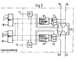
Bei einer Störung auf einem Übertragungsweg ändert sich die Zuordnung der Feststationen FS zu den Leitstellen LS so, daß jede Feststation FS über den ungestörten Teil des Übertragungsweges mit einer Leitstelle LS verbunden ist. Dazu sind in jeder Leitstelle LS Mittel vorhanden, den Ort der Störung festzustellen und über einen der beiden Steuerkanäle in den der Störungsstelle benachbarten Feststationen je einen Schalter SS (Fig. 2) zu betätigen, der den Übertragungsweg unterbricht, und auf beiden Seiten der Unterbrechung jeweils die Enden der Leitungen 1a bis 1d (Fig. 2) miteinander verbindet, und zwar 1a mit 1b und 1c mit 1d.
- Fig. 2
- zeigt ein Blockschaltbild eines Teils einer Feststation, aus dem hervorgeht, wie die Feststation an den Übertragungsweg angeschlossen ist. Dieser ist durch die zwei Leitungen 1a,c und 1d,b angedeutet. Die Leitungen sind mit PCM 30-Systemen ausgerüstet.
- Fig. 2
- shows a block diagram of part of a base station, from which it emerges how the base station is connected to the transmission path. This is indicated by the two lines 1a, c and 1d, b. The lines are equipped with
PCM 30 systems.
Im Zuge der Leitung 1a,c befindet sich ein Schalter S1, ein Digitalleitungssatz D1 und der Schalter SS, im Zuge der Leitungen 1d,b befindet sich ein Schalter S2, ein Digitalleitungssatz D2 und der Schalter SS.In the course of the line 1a, c there is a switch S1, a digital line set D1 and the switch SS, in the course of the
Der Digitalleitungssatz D1 ist mit einer ersten Takt/Alarmschaltung TA1 und zwei Multiplexern/Demultiplexern, Muldexer genannt, MX1 und MX2 verbunden. Der Digitalleitungssatz D2 ist mit einer zweiten Takt/Alarmschaltung TA2 und den Muldexern MX1 und MX2 verbunden. Die Takt/Alarmschaltung TA1 ist mit den Schaltern S1 und SS, die Takt/Alarmschaltung TA2 ist mit den Schaltern S2 und SS und beide Takt/Alarmschaltungen miteinander verbunden.The digital line set D1 is connected to a first clock / alarm circuit TA1 and two multiplexers / demultiplexers, called Muldexer, MX1 and MX2. The digital line set D2 is connected to a second clock / alarm circuit TA2 and the Muldexern MX1 and MX2. The clock / alarm circuit TA1 is connected to the switches S1 and SS, the clock / alarm circuit TA2 is connected to the switches S2 and SS and both clock / alarm circuits are connected to one another.
Bei störungsfreiem Betrieb des Nachrichtenübertragungssystems nehmen die Schalter S1, S2 und SS die in Fig. 2 gezeichnete Stellung ein. Der Digitalleitungssatz D1 liest aus den bei 1a ankommenden Signalen die für ihn bestimmten Signale aus und leitet sie über die Muldexer MX1 oder MX2 und weitere nicht gezeichnete Bauteile an die Mobilstationen weiter.When the message transmission system is operating correctly, the switches S1, S2 and SS assume the position shown in FIG. 2. The digital line set D1 reads the signals intended for it from the signals arriving at 1a and forwards them to the mobile stations via the Muldexer MX1 or MX2 and other components not shown.
Die anderen Signale gelangen über 1c an die nächste Feststation. In der umgekehrten Richtung werden die von den Mobilstationen stammenden Signale über die Muldexer MX1 oder MX2 und den Digitalleitungssatz 2 in die Leitung 1b eingespeist.The other signals go to the next base station via 1c. In the opposite direction, the signals originating from the mobile stations are fed into
Bei einem Ausfall des Digitalleitungssatzes D1 veranlaßt die Takt/Alarmschaltung TA1 durch Umschalten des Schalters S1 die Trennung des Digitalleitungssatzes D1 von der Leitung 1a, c, und setzt über die Takt/Alarmschaltung TA2 und den Digitalleitungssatz D2 auf dem Steuerkanal eine entsprechende Meldung an die zuständige Leitstelle ab. Diese veranlaßt , wie oben beschrieben, die Umschaltung des Schalters SS und ordnet die Feststation, und sofern erforderlich, die benachbarten Feststationen der anderen Leitstelle, oder, bei Ringleitungen, der anderen Einrichtung E am anderen Ende der Ringleitung zu. Der Digitalleitungssatz D2 überträgt nun in beiden Richtungen für diese Feststation bestimmten Nachrichten und Steuersignale.In the event of a failure of the digital line set D1, the clock / alarm circuit TA1 causes the switch of the switch S1 to separate the digital line set D1 from the line 1a, c, and sets a corresponding message on the control channel via the clock / alarm circuit TA2 and the digital line set D2 Control center. As described above, this switches the switch SS and assigns the base station and, if necessary, the neighboring base stations to the other control center, or, in the case of ring lines, to the other device E at the other end of the ring line. The digital line set D2 now transmits messages and control signals intended for this base station in both directions.
Die beiden Steuerkanäle jedes PCM 30-Systems dienen der Taktversorgung der Feststationen FS und der Übertragung aller benötigten Steuersignale. Dazu gehören insbesondere Signale zur Verteilung der Zeitmultiplexkanäle auf die Mobilstationen MS, zum Auf- und Abbau der Nachrichtenverbindung zwischen einer Mobilstation MS und einer Leitstelle LS, zum Weiterreichen der Mobilstation von einer Feststation zur benachbarten Feststation ohne Unterbrechung der Nachrichtenverbindung, zur Übertragung von Besetztzeichen etc. und zur Steuerung des Nachrichtenübertragungssystems im Normal- und Störungsfall.The two control channels of each
Die Takt/Alarmeinheiten TA1 und TA2 nehmen außer der Überwachung des jeweiligs zugeordneten Digitalleitungssatzes D1 oder D2 und der Verarbeitung von Alarmsignalen weitere Funktionen wahr, insbesondere die Taktsynchronisation oder die Taktversorgung der FeststationThe clock / alarm units TA1 and TA2 take out of monitoring of the respectively assigned digital line set D1 or D2 and the processing of alarm signals further functions, in particular the clock synchronization or the clock supply of the base station
Claims (8)
- Communication system comprising base stations (FS) and mobile stations (MS) capable of communicating with the base stations (FS) by radio, wherein groups of two or more of said base stations (FS) are controlled by a control station (LS), wherein all or part of the control stations (LS) are colocated with an interface facility (Ü) providing the connection to an automatic telephone system, and wherein the control stations (LS) are interconnected by transmission paths,
characterized in that the transmission paths interconnecting two control stations (LS) contain base stations (FS). - A communication system as claimed in claim 1, characterized in that on the transmission paths, separately for each direction of transmission, k time-division multiplex channels are provided for the intelligence signals and l time-division multiplex channels are provided for the control signals of the communication system.
- A communication system as claimed in claim 1 or 2, characterized in that each base station (FS) recognizes those of the intelligence and control signals transmitted on all time-division multiplex channels in both directions which are not intended for it, passes them on in the same direction of transmission to the neighboring base station, and processes the signals intended for it.
- A communication system as claimed in any one of the preceding claims, characterized in that on the transmission paths between two control station (LS), one control stations controls communications from and to a number of successive base stations (FS) beginning with the base station located nearest it, while the other control station controls communications from and to the other base stations.
- A communication systems as claimed in claim 4, characterized in that for communication between said one control station (LS) and the base stations (FS) controlled by said one control station and between said other control station and the base stations controlled by said other control stations, the seizure of the k channels begins at channel no. 1, that for direct communication between two control stations, the seizure of the k channels begins at channel no. k, and that further channels are seized in a continuous sequence.
- A communication system as claimed in any one of the preceding claims, characterized in that, if required, individual time-division multiplex channels are reserved or freed for messages to be transmitted with priority.
- A communication system as claimed in any one of the preceding claims, characterized in that the control stations (LS) detect and locate faults in the transmission paths and cause the faulty transmission path to be opened at the base stations adjacent to the fault, and that the base stations and communications from and to the base stations are controlled via the properly operating portion of the respective transmission path.
- A communication system as claimed in any one of the preceding claims, characterized in that on the occurrence of a fault within a base station, said base station sends a signal to a control station, whereupon the control station, if necessary, causes a part or all of the other base stations contained in the same transmission path as the faulty base station to be controlled either from the other end of the transmission path or from a control station other than that which controlled them prior to the occurrence of the fault.
Priority Applications (1)
| Application Number | Priority Date | Filing Date | Title |
|---|---|---|---|
| AT85103449T ATE72373T1 (en) | 1984-03-24 | 1985-03-23 | MESSAGE TRANSMISSION SYSTEM. |
Applications Claiming Priority (2)
| Application Number | Priority Date | Filing Date | Title |
|---|---|---|---|
| DE3411013A DE3411013A1 (en) | 1984-03-24 | 1984-03-24 | MESSAGE TRANSFER SYSTEM |
| DE3411013 | 1984-03-24 |
Publications (3)
| Publication Number | Publication Date |
|---|---|
| EP0156336A2 EP0156336A2 (en) | 1985-10-02 |
| EP0156336A3 EP0156336A3 (en) | 1988-03-23 |
| EP0156336B1 true EP0156336B1 (en) | 1992-01-29 |
Family
ID=6231596
Family Applications (1)
| Application Number | Title | Priority Date | Filing Date |
|---|---|---|---|
| EP19850103449 Expired - Lifetime EP0156336B1 (en) | 1984-03-24 | 1985-03-23 | Information transmission system |
Country Status (9)
| Country | Link |
|---|---|
| US (1) | US4686671A (en) |
| EP (1) | EP0156336B1 (en) |
| JP (1) | JPS611126A (en) |
| AT (1) | ATE72373T1 (en) |
| AU (1) | AU578271B2 (en) |
| CA (1) | CA1232329A (en) |
| DE (2) | DE3411013A1 (en) |
| ES (1) | ES8704064A1 (en) |
| GR (1) | GR850724B (en) |
Families Citing this family (22)
| Publication number | Priority date | Publication date | Assignee | Title |
|---|---|---|---|---|
| US5682256A (en) * | 1988-11-11 | 1997-10-28 | British Telecommunications Public Limited Company | Communications system |
| GB8826476D0 (en) * | 1988-11-11 | 1988-12-14 | British Telecomm | Communications system |
| US5084869A (en) * | 1990-01-31 | 1992-01-28 | At&T Bell Laboratories | Base station for mobile radio telecommunications systems |
| US5371780A (en) * | 1990-10-01 | 1994-12-06 | At&T Corp. | Communications resource assignment in a wireless telecommunications system |
| US5384826A (en) * | 1990-10-01 | 1995-01-24 | At&T Bell Laboratories | Distributed packetized switching cellular radio telephone communication system with handoff |
| CA2052466C (en) * | 1990-10-02 | 2001-05-08 | Masayuki Sakamoto | Method of handover and route diversity in mobile radio communication |
| JPH04142820A (en) * | 1990-10-04 | 1992-05-15 | Nippon Telegr & Teleph Corp <Ntt> | Base station transmission system in mobile communication |
| US5305467A (en) * | 1990-12-03 | 1994-04-19 | Ericsson Ge Mobile Communications Inc. | Local area network for flexible digital communications within and between RF base stations |
| IT1251119B (en) * | 1991-07-26 | 1995-05-04 | ISOFREQUENTIAL RADIO MOBILE NETWORK WITH CONNECTION BACKREST MADE BY A DROP / INSERT SYSTEM. | |
| FI88991C (en) * | 1991-10-03 | 1993-07-26 | Nokia Telecommunications Oy | Radio channel allocation procedure |
| US5422885A (en) * | 1992-06-01 | 1995-06-06 | Motorola, Inc. | Contention free local area network |
| FI108100B (en) * | 1993-06-23 | 2001-11-15 | Nokia Networks Oy | Communication method and communication system in a cellular radio network |
| AUPM593694A0 (en) * | 1994-05-27 | 1994-06-23 | Curtin University Of Technology | Underground microcellular communications network |
| AU708751B2 (en) * | 1994-05-27 | 1999-08-12 | Curtin University Of Technology | Cellular communications network |
| JP3231210B2 (en) * | 1995-03-03 | 2001-11-19 | 株式会社日立製作所 | Wireless communication system |
| JP2000507417A (en) | 1996-03-26 | 2000-06-13 | ブリティッシュ・テレコミュニケーションズ・パブリック・リミテッド・カンパニー | Alternative routing system for mobile telephone calls |
| DE19827027C2 (en) * | 1998-06-17 | 2000-05-18 | Siemens Ag | Base station |
| EP0982956A1 (en) * | 1998-08-25 | 2000-03-01 | Lucent Technologies Inc. | Base station equipment for a mobile cellular telecommunications network |
| EP1049344A1 (en) * | 1999-04-27 | 2000-11-02 | Lucent Technologies Inc. | Base station equipment for a mobile telecommunications network |
| US6628676B1 (en) * | 1999-06-21 | 2003-09-30 | Ericsson Inc. | Systems and methods for communicating messages among cascaded devices by bit shifting |
| WO2002015436A2 (en) * | 2000-08-15 | 2002-02-21 | Telefonaktiebolaget L.M. Ericsson | A method to utilize ring topology in communication channels linking cascaded radio heads |
| US20030021251A1 (en) * | 2001-07-30 | 2003-01-30 | Ramin Moshiri-Tafreshi | Self-healing wireless communication systems |
Family Cites Families (10)
| Publication number | Priority date | Publication date | Assignee | Title |
|---|---|---|---|---|
| GB1229149A (en) * | 1969-07-28 | 1971-04-21 | ||
| US3731002A (en) * | 1970-10-08 | 1973-05-01 | Bell Telephone Labor Inc | Interconnected loop data block transmission system |
| DE2931084C3 (en) * | 1979-07-31 | 1982-03-11 | Siemens AG, 1000 Berlin und 8000 München | Radio system |
| FR2472898B1 (en) * | 1979-12-27 | 1987-01-09 | Jeumont Schneider | DOUBLE LOOP TRANSMISSION NETWORK |
| FR2505124A1 (en) * | 1981-04-30 | 1982-11-05 | Jeumont Schneider | Telephone subscriber linking circuit - includes controlled series loops connecting subscribers each provided with auto-commutator |
| JPS58175335A (en) * | 1982-04-07 | 1983-10-14 | Hitachi Ltd | Loop-back controlling system of loop type data transmission system |
| JPS5940739A (en) * | 1982-08-30 | 1984-03-06 | Fujitsu Ltd | Loopback control system |
| ATE29098T1 (en) * | 1982-12-28 | 1987-09-15 | Ibm | ZRZ SWITCH USING A CLOSED LOOP CONNECTION. |
| FR2540694B1 (en) * | 1983-02-07 | 1988-05-13 | Trt Telecom Radio Electr | TIME MULTIPLEX LOOP TELECOMMUNICATION SYSTEM COMPRISING FIRST AND SECOND TRANSMISSION LINES |
| GB2143403B (en) * | 1983-07-15 | 1986-10-29 | Standard Telephones Cables Ltd | Telecommunication exchange |
-
1984
- 1984-03-24 DE DE3411013A patent/DE3411013A1/en not_active Withdrawn
-
1985
- 1985-03-14 AU AU39845/85A patent/AU578271B2/en not_active Ceased
- 1985-03-18 CA CA000476730A patent/CA1232329A/en not_active Expired
- 1985-03-21 GR GR850724A patent/GR850724B/el unknown
- 1985-03-22 ES ES541506A patent/ES8704064A1/en not_active Expired
- 1985-03-22 US US06/715,146 patent/US4686671A/en not_active Expired - Fee Related
- 1985-03-23 AT AT85103449T patent/ATE72373T1/en not_active IP Right Cessation
- 1985-03-23 DE DE8585103449T patent/DE3585292D1/en not_active Expired - Lifetime
- 1985-03-23 EP EP19850103449 patent/EP0156336B1/en not_active Expired - Lifetime
- 1985-03-25 JP JP60058621A patent/JPS611126A/en active Pending
Also Published As
| Publication number | Publication date |
|---|---|
| DE3585292D1 (en) | 1992-03-12 |
| AU578271B2 (en) | 1988-10-20 |
| EP0156336A2 (en) | 1985-10-02 |
| ES8704064A1 (en) | 1987-02-16 |
| GR850724B (en) | 1985-07-19 |
| ATE72373T1 (en) | 1992-02-15 |
| US4686671A (en) | 1987-08-11 |
| CA1232329A (en) | 1988-02-02 |
| EP0156336A3 (en) | 1988-03-23 |
| DE3411013A1 (en) | 1985-09-26 |
| AU3984585A (en) | 1985-09-26 |
| ES541506A0 (en) | 1987-02-16 |
| JPS611126A (en) | 1986-01-07 |
Similar Documents
| Publication | Publication Date | Title |
|---|---|---|
| EP0156336B1 (en) | Information transmission system | |
| DE69433624T2 (en) | BASIC STATION IN A CELLULAR RADIO ARRANGEMENT | |
| DE2903650C2 (en) | Circuit arrangement for a PCM switching system | |
| EP0281888A2 (en) | Circuit arrangement for the subscriber line circuits of a digital time division multiplex telecommunication exchange | |
| DE2619391B2 (en) | Message system with multiple access and decentralized switching | |
| EP0503486A2 (en) | Line monitoring for SDH-signals | |
| DE4422805C1 (en) | A method of loading software in communication systems with non-redundant, remote facilities | |
| EP0448927B1 (en) | Procedure for the transmission of time discrete information | |
| DE4207675C1 (en) | ||
| EP0162994A1 (en) | Communication network and its application | |
| DE2316478C3 (en) | Method for testing and maintaining the functionality of a time division multiplex switching network | |
| EP0879546A1 (en) | Digital signal transmission system | |
| DE2808666A1 (en) | DECENTRALLY CONTROLLED TELEPHONE SYSTEM | |
| DE3016546C2 (en) | ||
| EP0016396B1 (en) | Switching network with inverted grouping, especially for telephone switching systems | |
| EP0475135B1 (en) | Transmission system for connection network in communication networks | |
| EP0676906B1 (en) | System and method for the transmission of voice and service signals | |
| DE3151081C2 (en) | Method and arrangement for establishing a connection in a telecommunications system | |
| EP0024725B1 (en) | Circuit arrangement for connecting operator positions to a multistage time division multiplex telephone exchange | |
| DE2148411C3 (en) | Method for searching for free connection paths in a telecommunications network | |
| DE3037419C2 (en) | Circuit arrangement for monitoring impermissible connections in a switching network for switching systems, in particular telephone switching systems | |
| DE4315022C1 (en) | Digital TDM communications system - with spaced coupling fields coupled via intermediate adaptors within central module | |
| DE3609890C2 (en) | ||
| EP0539761B1 (en) | Method and system to detect a faulty channel within a channel group | |
| EP0023297A1 (en) | Digital telecommunication system |
Legal Events
| Date | Code | Title | Description |
|---|---|---|---|
| PUAI | Public reference made under article 153(3) epc to a published international application that has entered the european phase |
Free format text: ORIGINAL CODE: 0009012 |
|
| AK | Designated contracting states |
Designated state(s): AT BE CH DE FR GB IT LI LU NL SE |
|
| PUAL | Search report despatched |
Free format text: ORIGINAL CODE: 0009013 |
|
| AK | Designated contracting states |
Kind code of ref document: A3 Designated state(s): AT BE CH DE FR GB IT LI LU NL SE |
|
| 17P | Request for examination filed |
Effective date: 19880822 |
|
| 17Q | First examination report despatched |
Effective date: 19900827 |
|
| ITF | It: translation for a ep patent filed |
Owner name: DOTT. ANTONIO SERGI |
|
| GRAA | (expected) grant |
Free format text: ORIGINAL CODE: 0009210 |
|
| AK | Designated contracting states |
Kind code of ref document: B1 Designated state(s): AT BE CH DE FR GB IT LI LU NL SE |
|
| REF | Corresponds to: |
Ref document number: 72373 Country of ref document: AT Date of ref document: 19920215 Kind code of ref document: T |
|
| PGFP | Annual fee paid to national office [announced via postgrant information from national office to epo] |
Ref country code: LU Payment date: 19920225 Year of fee payment: 8 |
|
| GBT | Gb: translation of ep patent filed (gb section 77(6)(a)/1977) | ||
| REF | Corresponds to: |
Ref document number: 3585292 Country of ref document: DE Date of ref document: 19920312 |
|
| ET | Fr: translation filed | ||
| EPTA | Lu: last paid annual fee | ||
| RAP4 | Party data changed (patent owner data changed or rights of a patent transferred) |
Owner name: ALCATEL SEL AKTIENGESELLSCHAFT |
|
| PLBE | No opposition filed within time limit |
Free format text: ORIGINAL CODE: 0009261 |
|
| STAA | Information on the status of an ep patent application or granted ep patent |
Free format text: STATUS: NO OPPOSITION FILED WITHIN TIME LIMIT |
|
| PGFP | Annual fee paid to national office [announced via postgrant information from national office to epo] |
Ref country code: FR Payment date: 19921230 Year of fee payment: 9 |
|
| 26N | No opposition filed | ||
| PGFP | Annual fee paid to national office [announced via postgrant information from national office to epo] |
Ref country code: GB Payment date: 19930225 Year of fee payment: 9 |
|
| PG25 | Lapsed in a contracting state [announced via postgrant information from national office to epo] |
Ref country code: LU Free format text: LAPSE BECAUSE OF NON-PAYMENT OF DUE FEES Effective date: 19930323 |
|
| PGFP | Annual fee paid to national office [announced via postgrant information from national office to epo] |
Ref country code: SE Payment date: 19930324 Year of fee payment: 9 |
|
| PGFP | Annual fee paid to national office [announced via postgrant information from national office to epo] |
Ref country code: AT Payment date: 19930325 Year of fee payment: 9 |
|
| PGFP | Annual fee paid to national office [announced via postgrant information from national office to epo] |
Ref country code: NL Payment date: 19930331 Year of fee payment: 9 |
|
| PGFP | Annual fee paid to national office [announced via postgrant information from national office to epo] |
Ref country code: BE Payment date: 19930414 Year of fee payment: 9 |
|
| ITPR | It: changes in ownership of a european patent |
Owner name: CAMBIO RAGIONE SOCIALE;ALCATEL SEL AKTIENGESELLSCH |
|
| PGFP | Annual fee paid to national office [announced via postgrant information from national office to epo] |
Ref country code: DE Payment date: 19930512 Year of fee payment: 9 |
|
| PGFP | Annual fee paid to national office [announced via postgrant information from national office to epo] |
Ref country code: CH Payment date: 19930617 Year of fee payment: 9 |
|
| PG25 | Lapsed in a contracting state [announced via postgrant information from national office to epo] |
Ref country code: GB Effective date: 19940323 Ref country code: AT Effective date: 19940323 |
|
| PG25 | Lapsed in a contracting state [announced via postgrant information from national office to epo] |
Ref country code: SE Free format text: LAPSE BECAUSE OF NON-PAYMENT OF DUE FEES Effective date: 19940324 |
|
| PG25 | Lapsed in a contracting state [announced via postgrant information from national office to epo] |
Ref country code: LI Effective date: 19940331 Ref country code: CH Effective date: 19940331 Ref country code: BE Effective date: 19940331 |
|
| BERE | Be: lapsed |
Owner name: STANDARD ELEKTRIK LORENZ A.G. Effective date: 19940331 |
|
| PG25 | Lapsed in a contracting state [announced via postgrant information from national office to epo] |
Ref country code: NL Effective date: 19941001 |
|
| NLV4 | Nl: lapsed or anulled due to non-payment of the annual fee | ||
| GBPC | Gb: european patent ceased through non-payment of renewal fee |
Effective date: 19940323 |
|
| PG25 | Lapsed in a contracting state [announced via postgrant information from national office to epo] |
Ref country code: FR Effective date: 19941130 |
|
| REG | Reference to a national code |
Ref country code: CH Ref legal event code: PL |
|
| PG25 | Lapsed in a contracting state [announced via postgrant information from national office to epo] |
Ref country code: DE Effective date: 19941201 |
|
| REG | Reference to a national code |
Ref country code: FR Ref legal event code: ST |
|
| EUG | Se: european patent has lapsed |
Ref document number: 85103449.6 Effective date: 19941010 |