EP0156017B1 - Dispositif pour supporter le récipient d'un enroulement magnétique supraconducteur - Google Patents
Dispositif pour supporter le récipient d'un enroulement magnétique supraconducteur Download PDFInfo
- Publication number
- EP0156017B1 EP0156017B1 EP84115317A EP84115317A EP0156017B1 EP 0156017 B1 EP0156017 B1 EP 0156017B1 EP 84115317 A EP84115317 A EP 84115317A EP 84115317 A EP84115317 A EP 84115317A EP 0156017 B1 EP0156017 B1 EP 0156017B1
- Authority
- EP
- European Patent Office
- Prior art keywords
- support
- housing
- tubular
- outer housing
- winding
- Prior art date
- Legal status (The legal status is an assumption and is not a legal conclusion. Google has not performed a legal analysis and makes no representation as to the accuracy of the status listed.)
- Expired
Links
- 238000004804 winding Methods 0.000 claims description 49
- 230000005855 radiation Effects 0.000 claims description 28
- 239000000725 suspension Substances 0.000 claims description 14
- 229910052751 metal Inorganic materials 0.000 claims description 6
- 239000002184 metal Substances 0.000 claims description 6
- 239000004020 conductor Substances 0.000 claims description 5
- 239000000463 material Substances 0.000 claims description 4
- 239000011521 glass Substances 0.000 claims 2
- 229920003002 synthetic resin Polymers 0.000 claims 2
- 239000000057 synthetic resin Substances 0.000 claims 2
- 238000001816 cooling Methods 0.000 description 5
- 239000011152 fibreglass Substances 0.000 description 4
- 239000001307 helium Substances 0.000 description 3
- 229910052734 helium Inorganic materials 0.000 description 3
- SWQJXJOGLNCZEY-UHFFFAOYSA-N helium atom Chemical compound [He] SWQJXJOGLNCZEY-UHFFFAOYSA-N 0.000 description 3
- IJGRMHOSHXDMSA-UHFFFAOYSA-N Atomic nitrogen Chemical compound N#N IJGRMHOSHXDMSA-UHFFFAOYSA-N 0.000 description 2
- 230000001133 acceleration Effects 0.000 description 2
- 229910000952 Be alloy Inorganic materials 0.000 description 1
- RYGMFSIKBFXOCR-UHFFFAOYSA-N Copper Chemical compound [Cu] RYGMFSIKBFXOCR-UHFFFAOYSA-N 0.000 description 1
- 229910000831 Steel Inorganic materials 0.000 description 1
- RTAQQCXQSZGOHL-UHFFFAOYSA-N Titanium Chemical compound [Ti] RTAQQCXQSZGOHL-UHFFFAOYSA-N 0.000 description 1
- 229910052782 aluminium Inorganic materials 0.000 description 1
- XAGFODPZIPBFFR-UHFFFAOYSA-N aluminium Chemical compound [Al] XAGFODPZIPBFFR-UHFFFAOYSA-N 0.000 description 1
- 229910052802 copper Inorganic materials 0.000 description 1
- 239000010949 copper Substances 0.000 description 1
- 238000011161 development Methods 0.000 description 1
- 230000018109 developmental process Effects 0.000 description 1
- 230000010339 dilation Effects 0.000 description 1
- 238000006073 displacement reaction Methods 0.000 description 1
- 230000005484 gravity Effects 0.000 description 1
- 239000007788 liquid Substances 0.000 description 1
- 238000002595 magnetic resonance imaging Methods 0.000 description 1
- 229910052757 nitrogen Inorganic materials 0.000 description 1
- 230000035939 shock Effects 0.000 description 1
- 230000006641 stabilisation Effects 0.000 description 1
- 238000011105 stabilization Methods 0.000 description 1
- 239000010959 steel Substances 0.000 description 1
- 239000010936 titanium Substances 0.000 description 1
- 229910052719 titanium Inorganic materials 0.000 description 1
Images
Classifications
-
- G—PHYSICS
- G01—MEASURING; TESTING
- G01R—MEASURING ELECTRIC VARIABLES; MEASURING MAGNETIC VARIABLES
- G01R33/00—Arrangements or instruments for measuring magnetic variables
- G01R33/20—Arrangements or instruments for measuring magnetic variables involving magnetic resonance
- G01R33/28—Details of apparatus provided for in groups G01R33/44 - G01R33/64
- G01R33/38—Systems for generation, homogenisation or stabilisation of the main or gradient magnetic field
- G01R33/381—Systems for generation, homogenisation or stabilisation of the main or gradient magnetic field using electromagnets
- G01R33/3815—Systems for generation, homogenisation or stabilisation of the main or gradient magnetic field using electromagnets with superconducting coils, e.g. power supply therefor
-
- G—PHYSICS
- G01—MEASURING; TESTING
- G01R—MEASURING ELECTRIC VARIABLES; MEASURING MAGNETIC VARIABLES
- G01R33/00—Arrangements or instruments for measuring magnetic variables
- G01R33/20—Arrangements or instruments for measuring magnetic variables involving magnetic resonance
- G01R33/28—Details of apparatus provided for in groups G01R33/44 - G01R33/64
- G01R33/38—Systems for generation, homogenisation or stabilisation of the main or gradient magnetic field
- G01R33/3802—Manufacture or installation of magnet assemblies; Additional hardware for transportation or installation of the magnet assembly or for providing mechanical support to components of the magnet assembly
-
- Y—GENERAL TAGGING OF NEW TECHNOLOGICAL DEVELOPMENTS; GENERAL TAGGING OF CROSS-SECTIONAL TECHNOLOGIES SPANNING OVER SEVERAL SECTIONS OF THE IPC; TECHNICAL SUBJECTS COVERED BY FORMER USPC CROSS-REFERENCE ART COLLECTIONS [XRACs] AND DIGESTS
- Y10—TECHNICAL SUBJECTS COVERED BY FORMER USPC
- Y10S—TECHNICAL SUBJECTS COVERED BY FORMER USPC CROSS-REFERENCE ART COLLECTIONS [XRACs] AND DIGESTS
- Y10S505/00—Superconductor technology: apparatus, material, process
- Y10S505/825—Apparatus per se, device per se, or process of making or operating same
- Y10S505/883—Housing and mounting assembly with plural diverse electrical components
Definitions
- the invention relates to a device for holding a superconducting magnetic winding winding housing which is to be cooled to low temperature, which is surrounded by at least one radiation protection shield to be kept at a comparatively higher temperature and is arranged with the latter in an outer housing located at about room temperature, the Holding device has at least one rigid tubular support element which is arranged between the outer housing and the winding housing and is connected to the radiation protection shield and at least partially consists of poorly heat-conducting material.
- a mounting device is known from the report of the "National Accelerator Laboratory", USA, No. TM-334A, 2791,000 dated December 10, 1971 with the title "The Heim Column”.
- a winding housing in which the superconducting magnet winding to be deep-frozen is located, is often arranged within a vacuum or outer housing which is at room temperature of approximately 300 K.
- This winding housing is therefore also to be cooled to low temperature and is therefore also referred to as a helium housing.
- at least one radiation protection shield or housing is also provided between the outer and the winding housing and is generally kept at a temperature between about 40 K and 100 K.
- a mounting device with tension or support elements for all three spatial axes is required, via which the lowest possible amounts of heat are to be transferred to the deep box components.
- dynamic components such as e.g. due to accelerations during transport.
- the mounting device known from the report mentioned at the outset consists of a plurality of supporting elements which are to be arranged between the outer housing and the winding housing and are to be connected to a radiation shield.
- Each support element contains three enclosing tubular parts, the outer tube lying against the outer housing and the inner tube lying against the winding housing being made of glass fiber reinforced plastic and being connected to one another via the middle tube made of aluminum.
- Such mounting devices are, however, either oversized in order to be able to take over the dynamic additional loads during transport; or special transport supports are provided which must be removed before the magnet device is put into operation. Oversized mounting devices, however, lead to correspondingly high heat losses, while additional transport supports make handling the magnetic device difficult.
- the object of the present invention is therefore to improve the mounting device mentioned at the outset in such a way that relatively small amounts of heat are transferred from the outer housing to the cooled winding housing and that the additional dynamic loads occurring during transport can be absorbed without additional transport supports.
- the winding housing is suspended in the outer housing by means of at least one poorly heat-conducting suspension device, in that the tubular support element is designed as a pressure support which can be changed in length, so that a positive fit with the outer housing and with the winding housing located at room temperature is set and that this support element is attached to the radiation protection shield by means of a fastening device having a spring element such that always, ie even at operating temperature, there is a positive connection with the outer housing, while a gap of several mm in length is established between the support element and the winding housing at this temperature.
- the mounting device thus represents a combination of a suspension with additional pressure supports.
- the suspension of the cold weights is only in the stationary, i.e. effective in operation, while in the non-operating state, e.g. in the event of transport, in which the winding housing with the magnetic winding is at room temperature, via which one or more pressure supports there is an additional frictional connection between the outer housing and the winding housing. Since the pressure supports are always pressed onto the outer housing with the aid of the fastening device attached to the radiation protection shield, the frictional connection between the pressure supports and the housing is advantageously eliminated as the suspended winding housing cools down as a result of the associated shrinkage of this housing. The introduction of heat via the pressure supports on the winding housing is therefore excluded in the operating state. If the magnetic winding should be warmed up, for example for transport, the built-in support elements automatically come into operation again.
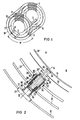
- FIG. 1 schematically shows a mounting arrangement according to the invention as an oblique view.
- Fig. 2 shows a longitudinal section through a support element for this mounting arrangement.
- the mounting device according to the invention can be provided for all superconducting magnet devices, the windings of which are to be arranged in their own winding housing, which is also to be cooled to the superconducting operating temperature and is located inside an outer housing, generally a vacuum housing, which is at room temperature.
- the magnet device can be, for example, the basic field magnet of a magnetic resonance imaging system. Such magnets must be transportable, so that the corresponding structure must be secured against the dynamic loads that occur. This requirement is to be met with the mounting device according to the invention.
- the mounting device comprises one or more suspension devices 2 and 3 known per se and a predetermined number of support elements 4 to 8 serving as pressure supports.
- a winding housing 11 is suspended within an outer housing 10, which one in the Figure does not enclose superconducting magnetic winding.
- a radiation shield 12 is arranged between the outer housing 10 and the winding housing 11 and is likewise carried by the suspension devices 2 and 3.
- Parts 11 and 12 are in operation, i.e. fixed in its cooled state solely by this suspension within the outer housing 10 in only the vertical direction. Only the gravity and the inertia of the suspended mass weight of the winding housing 11 and the radiation shield 12 act as stabilization for this purpose.
- Such suspension devices consist of a poorly heat-conducting material.
- the shape of the outer wall of the inner winding housing 11 and the inner wall of the outer housing 10 can be provided in the form of plate-shaped or disk-shaped holding parts made of glass fiber-reinforced plastic, via which the winding housing 11 and the radiation protection shield 12 are at their geodetically highest Places are mechanically rigidly connected to the outer housing 10.
- ropes or tapes made of poorly heat-conducting materials can also be used to suspend the winding housing 11 and the radiation protection shield 12. Since fastening the parts 11 and 12 solely by means of a suspension is not sufficient for the shocks or acceleration forces that occur in particular during transport, the additional support elements are provided for this case.
- the support elements 4 and 5 serve for frontal support in the axial direction, while three elements 6 of the support elements required for support in the radial direction to 8 can be seen.
- Fig. 2 the position of the radial support element 6 between corresponding sections of the inner winding housing 11 and the outer housing 10 is indicated both for the case of cooling of the winding housing and the radiation protection shield 12 and for the case that all parts are at room temperature.
- a sectional plane 14 is drawn in by the support element 6. Accordingly, the parts located on the left-hand side A of the cutting plane 14 should be in their position after cooling, while the right-hand half B of the figure should reflect the conditions at room temperature. Parts that assume a different position due to the cooling are identified by a dash on their reference number.
- the entire support element 6 is fastened to the radiation protection shield 12.
- this shield is provided with a tubular threaded bushing 18 made of metal, into which a corresponding metal threaded bushing 19 is to be screwed.
- This sleeve surrounds the tube support 16 and is rigidly connected to it, for example glued.
- a metal pressure piece 20 is inserted into the latter, via the widened, foot-like stop part 21, the tube support 16 can be supported on the outer housing 10.
- the pipe support 16 with the pressure piece 20 inserted into it is turned against the outer housing 10 by rotating the threaded sleeve 19 firmly surrounding it and secured against further rotation.
- the inner pipe support 17 is screwed into the pressure piece 20.
- the inner tube support 17 is firmly encased at its end facing the outer housing 10 with a metal threaded sleeve 22, which can be screwed into a corresponding thread on the inside of the pressure piece 20.
- the serving as a helium container Winding housing 11 and a further radiation protection shield 23, which may be provided and which can be kept at a temperature of approximately 30 K, are installed.
- the pipe support 17 is screwed back in the direction of the container wall of the winding housing 11 and secured against rotation by means of an intermediate piece 24 made of metal.
- This intermediate piece which is circular, divides the tube support 17 into a section 25 facing the winding housing 11 and a section 26 facing the outer housing 10.
- the two sections 25 and 26 are rigidly attached to the intermediate piece 24, for example glued on.
- the intermediate piece 24 fastened to the tube support 17 takes over the function of the radiation protection shield 12 which is interrupted in the region of the support element 6, for example by being thermally connected to the radiation protection shield 12 via copper strands not shown in the figure.
- the radiation protection shield 12 is expediently cooled first, shrinking toward a smaller radius.
- a spiral spring 27, for example made of a copper-beryllium alloy, is provided, which extends between the upper end 28 of the pressure piece 20 facing the winding container 11 and a foot-shaped end piece 29 that with the Radiation protection shield 12 rigidly connected threaded sleeve 19 is clamped.
- the dilation displacements associated with the cooling of the radiation protection shield 12 are then made possible by sliding movements of the tube support 16 with the threaded sleeve 19 with respect to the pressure piece 20 and with respect to the intermediate piece 24.
- a corresponding gap 30 is thus formed between the foot-like end piece 21 of the pressure piece 20 and the outer tube support 16 rigidly connected to the radiation protection shield 12. Since the support element 6 is only supported on a part of the outer housing 10, i.e. is not rigidly fastened there, slight sliding movements of the support element relative to the outer housing are also possible.
- tubular individual parts of the support element 6 have an annular cross-sectional shape.
- cross-sectional shapes such as rectangular or oval, suitable.
Landscapes
- Physics & Mathematics (AREA)
- Electromagnetism (AREA)
- Condensed Matter Physics & Semiconductors (AREA)
- General Physics & Mathematics (AREA)
- Containers, Films, And Cooling For Superconductive Devices (AREA)
- Magnetic Resonance Imaging Apparatus (AREA)
Claims (9)
Applications Claiming Priority (2)
| Application Number | Priority Date | Filing Date | Title |
|---|---|---|---|
| DE3407058 | 1984-02-27 | ||
| DE19843407058 DE3407058A1 (de) | 1984-02-27 | 1984-02-27 | Einrichtung zur halterung des gehaeuses einer supraleitenden magnetwicklung |
Publications (2)
| Publication Number | Publication Date |
|---|---|
| EP0156017A1 EP0156017A1 (fr) | 1985-10-02 |
| EP0156017B1 true EP0156017B1 (fr) | 1987-07-15 |
Family
ID=6228950
Family Applications (1)
| Application Number | Title | Priority Date | Filing Date |
|---|---|---|---|
| EP84115317A Expired EP0156017B1 (fr) | 1984-02-27 | 1984-12-12 | Dispositif pour supporter le récipient d'un enroulement magnétique supraconducteur |
Country Status (4)
| Country | Link |
|---|---|
| US (1) | US4599592A (fr) |
| EP (1) | EP0156017B1 (fr) |
| JP (1) | JPS60206007A (fr) |
| DE (2) | DE3407058A1 (fr) |
Families Citing this family (14)
| Publication number | Priority date | Publication date | Assignee | Title |
|---|---|---|---|---|
| JPS61278110A (ja) * | 1985-06-03 | 1986-12-09 | Mitsubishi Electric Corp | 超電導マグネツト |
| FR2597206B1 (fr) * | 1986-04-15 | 1988-06-17 | Thomson Cgr | Dispositif de fixation et de reglage d'un mandrin porteur de bobines de gradient |
| US4768008A (en) * | 1987-07-31 | 1988-08-30 | General Atomics | MRI magnet system with vessel having composite first wall |
| US4902995A (en) * | 1988-07-05 | 1990-02-20 | General Electric Company | Cable suspension system for cylindrical cryogenic vessels |
| US4935714A (en) * | 1988-07-05 | 1990-06-19 | General Electric Company | Low thermal conductance support for a radiation shield in a MR magnet |
| US4969064A (en) * | 1989-02-17 | 1990-11-06 | Albert Shadowitz | Apparatus with superconductors for producing intense magnetic fields |
| JP2549233B2 (ja) * | 1992-10-21 | 1996-10-30 | 三菱電機株式会社 | 超電導電磁石装置 |
| DE19933352C1 (de) * | 1999-07-16 | 2001-02-08 | Karlsruhe Forschzent | Axialer, kryotechnisch geeigneter Potentialtrenner |
| GB2420019B (en) * | 2002-12-10 | 2006-11-15 | Ge Med Sys Global Tech Co Llc | Support member for a superconducting magnet assembly |
| DE102005045595A1 (de) * | 2005-09-23 | 2007-04-26 | Siemens Ag | Maschine der Supraleitungstechnik mit Dämpferschirmteil |
| GB2456795B (en) * | 2008-01-24 | 2010-03-31 | Siemens Magnet Technology Ltd | A limiter for limiting the motion of components in a cryostat |
| GB2503448B (en) * | 2012-06-26 | 2014-06-18 | Siemens Plc | Modification of magnetic field using suspension elements |
| DE102015201373A1 (de) * | 2015-01-27 | 2016-07-28 | Siemens Aktiengesellschaft | Supraleitende Magnetanordnung, insbesondere für einen Magnetresonanztomographen |
| GB201515726D0 (en) * | 2015-09-04 | 2015-10-21 | Tokamak Energy Ltd | Support structures for HTS magnets |
Family Cites Families (4)
| Publication number | Priority date | Publication date | Assignee | Title |
|---|---|---|---|---|
| DE1514633B1 (de) * | 1965-12-07 | 1970-11-12 | Siemens Ag | Einrichtung,die innerhalb eines Gehaeuses eine waermeisolierte und gekuehlte supraleitende Wicklung enthaelt |
| DE2446716C3 (de) * | 1974-09-30 | 1980-01-24 | Siemens Ag, 1000 Berlin Und 8000 Muenchen | Haltevorrichtung für ein mit Zugankern innerhalb eines Vakuumgehäuses befestigtes Wicklungsgehäuse |
| DE2523007C3 (de) * | 1975-05-23 | 1978-05-24 | Siemens Ag, 1000 Berlin Und 8000 Muenchen | Vorrichtung zur Übertragung großer Kräfte |
| DE3027605C2 (de) * | 1980-07-21 | 1983-01-05 | Siemens AG, 1000 Berlin und 8000 München | Vorrichtung zur Übertragung großer Kräfte |
-
1984
- 1984-02-27 DE DE19843407058 patent/DE3407058A1/de not_active Withdrawn
- 1984-12-12 DE DE8484115317T patent/DE3464820D1/de not_active Expired
- 1984-12-12 EP EP84115317A patent/EP0156017B1/fr not_active Expired
-
1985
- 1985-02-04 US US06/697,627 patent/US4599592A/en not_active Expired - Fee Related
- 1985-02-26 JP JP60037350A patent/JPS60206007A/ja active Pending
Also Published As
| Publication number | Publication date |
|---|---|
| EP0156017A1 (fr) | 1985-10-02 |
| DE3464820D1 (en) | 1987-08-20 |
| DE3407058A1 (de) | 1985-08-29 |
| JPS60206007A (ja) | 1985-10-17 |
| US4599592A (en) | 1986-07-08 |
Similar Documents
| Publication | Publication Date | Title |
|---|---|---|
| EP0156017B1 (fr) | Dispositif pour supporter le récipient d'un enroulement magnétique supraconducteur | |
| DE69836252T2 (de) | Tragende Mittel für NMR-Kryostatsystemen | |
| DE68907278T2 (de) | Supraleitender Magnetresonanz-Magnet. | |
| EP0332979A2 (fr) | Support magnétique avec aimants permanents pour absorber des contraintes radiales de paliers | |
| DE69126813T2 (de) | Supraleitender Magnet | |
| EP0145074B1 (fr) | Tube à rayons X à anode rotative avec un palier à glissement | |
| DE60029406T2 (de) | Offene supraleitende einen Heliumbehälter integrierende Magnetanordnung | |
| DE2502714A1 (de) | Elektromagnet | |
| DE69930487T2 (de) | Aufhängungseinheit für einen supraleitenden Magnet | |
| DE19947539B4 (de) | Gradientenspulenanordnung mit Dämpfung innerer mechanischer Schwingungen | |
| DE102019209160B3 (de) | Kryostatanordnung mit federndem, wärmeleitendem Verbindungselement | |
| EP3382411A1 (fr) | Dispositif formant cryostat pourvu de col tubulaire à une structure porteuse et un col tubulaire entourant la structure porteuse destiné à réduire la consommation de cryogène | |
| DE102006018650B4 (de) | Supraleitende Magnetanordung mit vermindertem Wärmeeintrag in tiefkalte Bereiche | |
| EP1381531B1 (fr) | Ensemble magnetique pour la sustentation et le guidage de vehicules et de systemes de transport a sustentation | |
| DE102015225731B3 (de) | Leicht zugängliche tiefgekühlte NMR Shim-Anordnung | |
| EP1895315A2 (fr) | Arrangement magnétique de bobine séparée doté d'une construction mécanique améliorée | |
| EP0376108B1 (fr) | Téléscope avec stabilisation d'image | |
| US5023584A (en) | Magnet cartridge for magnetic resonance magnet | |
| DE69120708T2 (de) | Supraleitender Magnet | |
| DE4129547C2 (de) | Cryostat | |
| DE102015201373A1 (de) | Supraleitende Magnetanordnung, insbesondere für einen Magnetresonanztomographen | |
| DE8804371U1 (de) | Supraleitendes Kabel mit oxidkeramischem Hochtemperatursupraleiter-Material | |
| DE2247716C3 (de) | Tieftemperaturkabelstück | |
| EP0004009A1 (fr) | Structure d'un supraconducteur et son procédé de fabrication | |
| DE19715356A1 (de) | Vorrichtung zur Lagerung von schnelldrehenden Rotoren |
Legal Events
| Date | Code | Title | Description |
|---|---|---|---|
| PUAI | Public reference made under article 153(3) epc to a published international application that has entered the european phase |
Free format text: ORIGINAL CODE: 0009012 |
|
| AK | Designated contracting states |
Designated state(s): DE GB NL |
|
| 17P | Request for examination filed |
Effective date: 19851106 |
|
| 17Q | First examination report despatched |
Effective date: 19860612 |
|
| GRAA | (expected) grant |
Free format text: ORIGINAL CODE: 0009210 |
|
| AK | Designated contracting states |
Kind code of ref document: B1 Designated state(s): DE GB NL |
|
| REF | Corresponds to: |
Ref document number: 3464820 Country of ref document: DE Date of ref document: 19870820 |
|
| PGFP | Annual fee paid to national office [announced via postgrant information from national office to epo] |
Ref country code: NL Payment date: 19871231 Year of fee payment: 4 |
|
| PLBE | No opposition filed within time limit |
Free format text: ORIGINAL CODE: 0009261 |
|
| STAA | Information on the status of an ep patent application or granted ep patent |
Free format text: STATUS: NO OPPOSITION FILED WITHIN TIME LIMIT |
|
| 26N | No opposition filed | ||
| PGFP | Annual fee paid to national office [announced via postgrant information from national office to epo] |
Ref country code: DE Payment date: 19890223 Year of fee payment: 5 |
|
| PG25 | Lapsed in a contracting state [announced via postgrant information from national office to epo] |
Ref country code: NL Effective date: 19890701 |
|
| NLV4 | Nl: lapsed or anulled due to non-payment of the annual fee | ||
| PG25 | Lapsed in a contracting state [announced via postgrant information from national office to epo] |
Ref country code: GB Effective date: 19891212 |
|
| GBPC | Gb: european patent ceased through non-payment of renewal fee | ||
| PG25 | Lapsed in a contracting state [announced via postgrant information from national office to epo] |
Ref country code: DE Effective date: 19900901 |