EP0155893B1 - Gerät für chemische Reaktion von unterschiedlichen Chemikalien durch Nassverfahren - Google Patents
Gerät für chemische Reaktion von unterschiedlichen Chemikalien durch Nassverfahren Download PDFInfo
- Publication number
- EP0155893B1 EP0155893B1 EP85420033A EP85420033A EP0155893B1 EP 0155893 B1 EP0155893 B1 EP 0155893B1 EP 85420033 A EP85420033 A EP 85420033A EP 85420033 A EP85420033 A EP 85420033A EP 0155893 B1 EP0155893 B1 EP 0155893B1
- Authority
- EP
- European Patent Office
- Prior art keywords
- opening
- cavity
- recipient
- stack
- neck
- Prior art date
- Legal status (The legal status is an assumption and is not a legal conclusion. Google has not performed a legal analysis and makes no representation as to the accuracy of the status listed.)
- Expired
Links
- 238000006243 chemical reaction Methods 0.000 title claims abstract description 27
- 238000000034 method Methods 0.000 title claims description 26
- 239000000126 substance Substances 0.000 title description 2
- 230000004888 barrier function Effects 0.000 claims abstract description 4
- 230000000630 rising effect Effects 0.000 claims abstract description 3
- 239000003153 chemical reaction reagent Substances 0.000 claims description 12
- 239000003517 fume Substances 0.000 claims description 6
- 230000008569 process Effects 0.000 claims description 6
- XLYOFNOQVPJJNP-UHFFFAOYSA-N water Substances O XLYOFNOQVPJJNP-UHFFFAOYSA-N 0.000 claims description 6
- 239000012530 fluid Substances 0.000 claims description 4
- 238000005259 measurement Methods 0.000 claims description 4
- 230000014759 maintenance of location Effects 0.000 claims description 3
- 230000015572 biosynthetic process Effects 0.000 claims description 2
- 230000001105 regulatory effect Effects 0.000 claims description 2
- 239000012780 transparent material Substances 0.000 claims 1
- 238000010438 heat treatment Methods 0.000 abstract description 13
- 150000001875 compounds Chemical class 0.000 abstract description 9
- 230000033558 biomineral tissue development Effects 0.000 abstract description 7
- 238000010521 absorption reaction Methods 0.000 abstract description 4
- QAOWNCQODCNURD-UHFFFAOYSA-N Sulfuric acid Chemical compound OS(O)(=O)=O QAOWNCQODCNURD-UHFFFAOYSA-N 0.000 description 14
- 210000003739 neck Anatomy 0.000 description 11
- 238000011282 treatment Methods 0.000 description 8
- 239000003507 refrigerant Substances 0.000 description 7
- 239000000203 mixture Substances 0.000 description 6
- 229910017604 nitric acid Inorganic materials 0.000 description 6
- GRYLNZFGIOXLOG-UHFFFAOYSA-N Nitric acid Chemical compound O[N+]([O-])=O GRYLNZFGIOXLOG-UHFFFAOYSA-N 0.000 description 5
- 239000002253 acid Substances 0.000 description 5
- 238000001704 evaporation Methods 0.000 description 5
- 230000008020 evaporation Effects 0.000 description 5
- 238000009835 boiling Methods 0.000 description 4
- 238000001816 cooling Methods 0.000 description 4
- 238000009434 installation Methods 0.000 description 4
- 238000012544 monitoring process Methods 0.000 description 4
- 238000007254 oxidation reaction Methods 0.000 description 4
- 238000010992 reflux Methods 0.000 description 4
- DOBUSJIVSSJEDA-UHFFFAOYSA-L 1,3-dioxa-2$l^{6}-thia-4-mercuracyclobutane 2,2-dioxide Chemical compound [Hg+2].[O-]S([O-])(=O)=O DOBUSJIVSSJEDA-UHFFFAOYSA-L 0.000 description 3
- 230000008901 benefit Effects 0.000 description 3
- 239000003054 catalyst Substances 0.000 description 3
- 238000004880 explosion Methods 0.000 description 3
- 239000006260 foam Substances 0.000 description 3
- 230000003647 oxidation Effects 0.000 description 3
- SQGYOTSLMSWVJD-UHFFFAOYSA-N silver(1+) nitrate Chemical compound [Ag+].[O-]N(=O)=O SQGYOTSLMSWVJD-UHFFFAOYSA-N 0.000 description 3
- 238000009834 vaporization Methods 0.000 description 3
- 230000008016 vaporization Effects 0.000 description 3
- CDBYLPFSWZWCQE-UHFFFAOYSA-L Sodium Carbonate Chemical compound [Na+].[Na+].[O-]C([O-])=O CDBYLPFSWZWCQE-UHFFFAOYSA-L 0.000 description 2
- 210000001015 abdomen Anatomy 0.000 description 2
- 150000007513 acids Chemical class 0.000 description 2
- 230000006872 improvement Effects 0.000 description 2
- 239000000463 material Substances 0.000 description 2
- 229940074994 mercuric sulfate Drugs 0.000 description 2
- 229910000372 mercury(II) sulfate Inorganic materials 0.000 description 2
- 238000012986 modification Methods 0.000 description 2
- 230000004048 modification Effects 0.000 description 2
- VLTRZXGMWDSKGL-UHFFFAOYSA-N perchloric acid Chemical compound OCl(=O)(=O)=O VLTRZXGMWDSKGL-UHFFFAOYSA-N 0.000 description 2
- 238000005086 pumping Methods 0.000 description 2
- 230000035484 reaction time Effects 0.000 description 2
- 230000009467 reduction Effects 0.000 description 2
- 238000007127 saponification reaction Methods 0.000 description 2
- 239000000779 smoke Substances 0.000 description 2
- UOCLXMDMGBRAIB-UHFFFAOYSA-N 1,1,1-trichloroethane Chemical compound CC(Cl)(Cl)Cl UOCLXMDMGBRAIB-UHFFFAOYSA-N 0.000 description 1
- UTPYTEWRMXITIN-YDWXAUTNSA-N 1-methyl-3-[(e)-[(3e)-3-(methylcarbamothioylhydrazinylidene)butan-2-ylidene]amino]thiourea Chemical compound CNC(=S)N\N=C(/C)\C(\C)=N\NC(=S)NC UTPYTEWRMXITIN-YDWXAUTNSA-N 0.000 description 1
- RNAMYOYQYRYFQY-UHFFFAOYSA-N 2-(4,4-difluoropiperidin-1-yl)-6-methoxy-n-(1-propan-2-ylpiperidin-4-yl)-7-(3-pyrrolidin-1-ylpropoxy)quinazolin-4-amine Chemical compound N1=C(N2CCC(F)(F)CC2)N=C2C=C(OCCCN3CCCC3)C(OC)=CC2=C1NC1CCN(C(C)C)CC1 RNAMYOYQYRYFQY-UHFFFAOYSA-N 0.000 description 1
- 101710134784 Agnoprotein Proteins 0.000 description 1
- 229910001369 Brass Inorganic materials 0.000 description 1
- 241000195940 Bryophyta Species 0.000 description 1
- ZAMOUSCENKQFHK-UHFFFAOYSA-N Chlorine atom Chemical compound [Cl] ZAMOUSCENKQFHK-UHFFFAOYSA-N 0.000 description 1
- 102000002322 Egg Proteins Human genes 0.000 description 1
- 108010000912 Egg Proteins Proteins 0.000 description 1
- KWYUFKZDYYNOTN-UHFFFAOYSA-M Potassium hydroxide Chemical compound [OH-].[K+] KWYUFKZDYYNOTN-UHFFFAOYSA-M 0.000 description 1
- XSQUKJJJFZCRTK-UHFFFAOYSA-N Urea Chemical compound NC(N)=O XSQUKJJJFZCRTK-UHFFFAOYSA-N 0.000 description 1
- -1 above Chemical class 0.000 description 1
- 239000006096 absorbing agent Substances 0.000 description 1
- 230000006978 adaptation Effects 0.000 description 1
- 238000013019 agitation Methods 0.000 description 1
- 230000001476 alcoholic effect Effects 0.000 description 1
- QVGXLLKOCUKJST-UHFFFAOYSA-N atomic oxygen Chemical compound [O] QVGXLLKOCUKJST-UHFFFAOYSA-N 0.000 description 1
- 239000010951 brass Substances 0.000 description 1
- 239000004202 carbamide Substances 0.000 description 1
- 239000000460 chlorine Substances 0.000 description 1
- 229910052801 chlorine Inorganic materials 0.000 description 1
- 238000004891 communication Methods 0.000 description 1
- 238000009833 condensation Methods 0.000 description 1
- 230000005494 condensation Effects 0.000 description 1
- 239000000470 constituent Substances 0.000 description 1
- 238000007796 conventional method Methods 0.000 description 1
- KZNICNPSHKQLFF-UHFFFAOYSA-N dihydromaleimide Natural products O=C1CCC(=O)N1 KZNICNPSHKQLFF-UHFFFAOYSA-N 0.000 description 1
- 230000000694 effects Effects 0.000 description 1
- 230000008030 elimination Effects 0.000 description 1
- 238000003379 elimination reaction Methods 0.000 description 1
- 238000005265 energy consumption Methods 0.000 description 1
- 238000011156 evaluation Methods 0.000 description 1
- 230000002349 favourable effect Effects 0.000 description 1
- 239000011521 glass Substances 0.000 description 1
- 229910000856 hastalloy Inorganic materials 0.000 description 1
- 238000006460 hydrolysis reaction Methods 0.000 description 1
- 229910052500 inorganic mineral Inorganic materials 0.000 description 1
- 239000007788 liquid Substances 0.000 description 1
- 229960005337 lysine hydrochloride Drugs 0.000 description 1
- 239000002184 metal Substances 0.000 description 1
- 239000011707 mineral Substances 0.000 description 1
- 235000010755 mineral Nutrition 0.000 description 1
- 239000003595 mist Substances 0.000 description 1
- GQPLMRYTRLFLPF-UHFFFAOYSA-N nitrous oxide Inorganic materials [O-][N+]#N GQPLMRYTRLFLPF-UHFFFAOYSA-N 0.000 description 1
- 150000002894 organic compounds Chemical class 0.000 description 1
- 150000002902 organometallic compounds Chemical class 0.000 description 1
- 239000012476 oxidizable substance Substances 0.000 description 1
- 239000001301 oxygen Substances 0.000 description 1
- 229910052760 oxygen Inorganic materials 0.000 description 1
- 229920000515 polycarbonate Polymers 0.000 description 1
- 239000004417 polycarbonate Substances 0.000 description 1
- 229940072033 potash Drugs 0.000 description 1
- BWHMMNNQKKPAPP-UHFFFAOYSA-L potassium carbonate Substances [K+].[K+].[O-]C([O-])=O BWHMMNNQKKPAPP-UHFFFAOYSA-L 0.000 description 1
- 235000015320 potassium carbonate Nutrition 0.000 description 1
- KMUONIBRACKNSN-UHFFFAOYSA-N potassium dichromate Chemical compound [K+].[K+].[O-][Cr](=O)(=O)O[Cr]([O-])(=O)=O KMUONIBRACKNSN-UHFFFAOYSA-N 0.000 description 1
- 230000037452 priming Effects 0.000 description 1
- 238000012545 processing Methods 0.000 description 1
- 230000000135 prohibitive effect Effects 0.000 description 1
- 230000001902 propagating effect Effects 0.000 description 1
- 230000005855 radiation Effects 0.000 description 1
- 238000005057 refrigeration Methods 0.000 description 1
- 230000000717 retained effect Effects 0.000 description 1
- 229910001220 stainless steel Inorganic materials 0.000 description 1
- 239000010935 stainless steel Substances 0.000 description 1
- 229960002317 succinimide Drugs 0.000 description 1
- 238000009827 uniform distribution Methods 0.000 description 1
- 230000000007 visual effect Effects 0.000 description 1
Images
Classifications
-
- B—PERFORMING OPERATIONS; TRANSPORTING
- B01—PHYSICAL OR CHEMICAL PROCESSES OR APPARATUS IN GENERAL
- B01J—CHEMICAL OR PHYSICAL PROCESSES, e.g. CATALYSIS OR COLLOID CHEMISTRY; THEIR RELEVANT APPARATUS
- B01J19/00—Chemical, physical or physico-chemical processes in general; Their relevant apparatus
- B01J19/08—Processes employing the direct application of electric or wave energy, or particle radiation; Apparatus therefor
- B01J19/12—Processes employing the direct application of electric or wave energy, or particle radiation; Apparatus therefor employing electromagnetic waves
- B01J19/122—Incoherent waves
- B01J19/126—Microwaves
-
- H—ELECTRICITY
- H05—ELECTRIC TECHNIQUES NOT OTHERWISE PROVIDED FOR
- H05B—ELECTRIC HEATING; ELECTRIC LIGHT SOURCES NOT OTHERWISE PROVIDED FOR; CIRCUIT ARRANGEMENTS FOR ELECTRIC LIGHT SOURCES, IN GENERAL
- H05B6/00—Heating by electric, magnetic or electromagnetic fields
- H05B6/64—Heating using microwaves
- H05B6/80—Apparatus for specific applications
Definitions
- the present invention relates to the technical field of the chemical reaction of mineral, organic or organometallic compounds.
- a conventional method consists in placing in a vase, for example of the flask type, a dose of compound to be analyzed, as well as the necessary additional volume of specific concentrated reagent.
- the vase is then heated and constantly monitored by an operator who is responsible for periodically adjusting the calories transmitted to the vase, to avoid the appearance of foam and overflowing of the product.
- the operator must also shake, periodically but frequently, the mixture subjected to heating, in order to maintain good homogeneity of the dissolved and heated compound.
- US Patent 4,080,168 teaches such a proposal and recommends the use of a microwave oven in the cavity of which is placed a vase containing the sample to be treated.
- a microwave oven is known for its properties of absence of thermal inertia, which makes it possible to more precisely regulate the energy transmitted to the sample.
- the high evaporation of the reagent (s) also poses a practical problem which is difficult to solve. In the most frequent case where the operator must necessarily intervene to periodically extract and replace the sample in the application cavity, it is understood that the gripping of the vase should not pose any problem. However, due to the high evaporation, the outer face of the wall of the vase is covered with a layer of droplets which may have serious consequences on the environment when the reagent used is an acid, as in the case of mineralization or oxidation.
- the strong evaporation also has the negative result of developing, inside the cavity where the container is placed, a mist of vapor opposing any visual appreciation of the progress of the reaction in progress.
- the subject of the present invention is a new wet chemical reaction apparatus, still employing the application of microwaves, but the particular structure of which precisely allows the drawbacks of the current methods and, more precisely, of those attached, to be eliminated. to the technique according to US Patent 4,080,168.
- the structural characteristics of the device according to the invention have, moreover, made it possible to note the obtaining of surprising results in the conduct of the mineralization treatment of certain products.
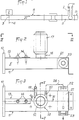
- Fig. 4 and fig. 5 are sectional elevations taken, respectively, along lines IV-IV and V-V of FIG. 3.
- Fig. 1 schematically shows an apparatus for subjecting a chemical reaction by a wet process to a compound placed in a container 1 into which is also introduced at least one specific reagent.
- the apparatus comprises a microwave generator 2 comprising an antenna 3 emitting, from an emissive plane 4, microwaves in an application cavity 5 in which the container 1 must be placed.
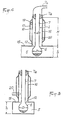
- the container 1, as shown in FIG. 4, is made of glass to include, at its base, a retention capacity 6 of at least semi-spherical shape and extended by a neck 7 of great length, of constant cylindrical section.
- the container 7 is shaped in such a way that the capacity 6 is similar to a substantially spherical volume, such as a bulb, whose diameter D, taken perpendicular to the axis of the neck 7, is greater than that d of the last.
- the container 1 could also be made, for example, of polycarbonate and have a different shape, depending on the nature of the compound and the chemical reaction to be subjected to it.
- the container 1 could be cylindrical with a flat bottom or semi-spherical.
- the cavity 5 is, in this case, constituted by the terminal segment 8 of a waveguide 9.
- the segment 8 comprises technical means usually used to ensure and improve the routing and propagation of the microwaves emitted by the antenna 3 in a general direction of propagation along the arrow f i .
- the segment 8, as illustrated in FIGS. 2 to 5, has, from a connection flange 10, a constant section, substantially equivalent to that of the guide 9.
- the segment 8 is, for example, constituted by a parallelepipedic envelope 11 made of stainless steel or brass.
- the envelope 11 has, in its upper horizontal wall, a circular opening 12, permanently open and whose diameter is equal, apart from play, to the diameter D of the capacity 6 of the container 1.
- the circular opening 12 is located at a determined distance from the emissive plane 4, so that its vertical axis corresponds, substantially, to a zone of formation of a belly by the waves emitted by the antenna 3 and propagating in the direction of the arrow f l .
- the envelope 11 is provided with a tuning device 13 placed between the flange 10 and the opening 12.
- the tuning device 13 consists of two metal rods 14 carried, in an adjustable manner, by the upper wall 15 of the segment 8 to extend in a direction perpendicular to the longitudinal axis of the envelope 11 inside the latter, being both placed on the longitudinal axis of the segment.
- Figs. 4 and 5 show an important constructive characteristic of the invention according to which the cavity 5 has, at least in line with the opening 12, a height h corresponding substantially to excess in diameter D.
- the capacity 6 of the container can be placed inside the cavity 5 by being introduced through the opening 12, while the neck 7 rises above the wall 15.
- the opening 12 is bordered by a tubular chimney 16 of cylindrical shape, of constant section.
- the chimney 16 rises over a height H chosen as a function of the section of the opening 12 and of the frequency of emission of the microwaves, so as to constitute an absorption barrier opposing the propagation of these microwave outside the cavity 5.
- H a height chosen as a function of the section of the opening 12 and of the frequency of emission of the microwaves, so as to constitute an absorption barrier opposing the propagation of these microwave outside the cavity 5.
- H height chosen as a function of the section of the opening 12 and of the frequency of emission of the microwaves, so as to constitute an absorption barrier opposing the propagation of these microwave outside the cavity 5.
- H height chosen as a function of the section of the opening 12 and of the frequency of emission of the microwaves, so as to constitute an absorption barrier opposing the propagation of these microwave outside the cavity 5.
- This excess measurement is provided for adaptation
- the chimney 16 is surrounded by a sleeve 17 delimiting an annular chamber 18.
- the sleeve 17 comprises two pipes 19 and 20 for connection to a circuit for circulating an appropriate fluid, making it possible to regulate the temperature of the chimney and, by Consequently, that of the neck 7 as a function of the chemical reaction to be carried out.
- the temperature control fluid is, for example, constituted by water.
- the end of the envelope 11, opposite the flange 10 relative to the chimney 7, is preferably occupied by a chamber 21 water trap.
- This chamber is in relation to two fittings 22 and 23 attached to the lateral faces of the casing 11 for the connection with a water circulation circuit.
- the connector 22, corresponding to the inlet is connected by a pipe 24 to the outlet pipe 20 of the annular chamber 18.
- the chamber 21 could be replaced by a dry absorber or, possibly again, suppressed provided that the standing wave rate during application remains admissible by the generator and does not significantly shorten its life.
- Microwave oven Type LMI, Process interrupted due to the departure of sulfuric acid and model LAB 607, 600 W) obtaining a carbonaceous mass. Pollution of the oven and
- Microwave oven Reaction stops after 15 min (heating time + cooling time) because vaporization of H Z S0 4 . Obtaining a yellowish solution. N 15.2%. Pollution of the enclosure.
- Microwave oven 50 min including exposure time + handling time + cooling time. Driving difficulties due to the heating power and the release of nitrous vapors. Add more than 8 ml of nitric acid.
- 45 min invention comprising six successive 100 W oxidation and 120 W elimination sequences. Addition of more than 8 ml of nitric acid. No pollution.
- Microwave oven Exposure time 6 minutes 30 seconds. Constant monitoring (presence of mosses). Clear liquid. N + 13%.
- Microwave oven Heating time + cooling time 10 min. End of reaction time> 10 min. Very difficult to control reaction (very short heating time) due to the boiling of the acid mixture. Losses and pollution.
- Microwave oven The boiling of the medium is so rapid ( ⁇ 10 seconds) that it was not possible, despite supervision, to avoid the overflow of the reagents and the loss of part of the sample in the oven.
- Another advantage of the object of the invention lies in the fact that the presence of the annular chamber 17 makes it possible to modulate and regulate the temperature of the neck 7, despite the rise in temperature of the product placed in the bulb 6. This allows favor, depending on the type of reaction, either a cooling favorable to condensation of the vapors along the neck 7, or a heating of the latter in the case, in particular, of the mineralization phase by reduction to ensure the evaporation of the products of reaction, as in Example A-3. In such a case, the communication between the chamber 21 and the chamber 18 is eliminated, the chamber 18 then being placed in relation to a circuit for supplying a fluid whose temperature is regulated as a function of the reaction implemented.
- Yet another advantage lies in the fact that the open upper end of the neck is accessible and makes it possible to adapt the material specific to the reaction to be carried out, such as a refrigeration column according to examples B-2 and 3 or examples C -1 and 2.
Landscapes
- Chemical & Material Sciences (AREA)
- Electromagnetism (AREA)
- Physics & Mathematics (AREA)
- Organic Chemistry (AREA)
- Toxicology (AREA)
- General Health & Medical Sciences (AREA)
- Health & Medical Sciences (AREA)
- Chemical Kinetics & Catalysis (AREA)
- Physical Or Chemical Processes And Apparatus (AREA)
- Organic Low-Molecular-Weight Compounds And Preparation Thereof (AREA)
- Devices For Use In Laboratory Experiments (AREA)
- Investigating Or Analyzing Non-Biological Materials By The Use Of Chemical Means (AREA)
- Control Of Non-Electrical Variables (AREA)
Claims (9)
Priority Applications (1)
| Application Number | Priority Date | Filing Date | Title |
|---|---|---|---|
| AT85420033T ATE45457T1 (de) | 1984-03-02 | 1985-02-26 | Geraet fuer chemische reaktion von unterschiedlichen chemikalien durch nassverfahren. |
Applications Claiming Priority (2)
| Application Number | Priority Date | Filing Date | Title |
|---|---|---|---|
| FR8403496A FR2560529B1 (fr) | 1984-03-02 | 1984-03-02 | Appareil de reaction chimique par voie humide de produits divers |
| FR8403496 | 1984-03-02 |
Publications (2)
| Publication Number | Publication Date |
|---|---|
| EP0155893A1 EP0155893A1 (de) | 1985-09-25 |
| EP0155893B1 true EP0155893B1 (de) | 1989-08-09 |
Family
ID=9301774
Family Applications (1)
| Application Number | Title | Priority Date | Filing Date |
|---|---|---|---|
| EP85420033A Expired EP0155893B1 (de) | 1984-03-02 | 1985-02-26 | Gerät für chemische Reaktion von unterschiedlichen Chemikalien durch Nassverfahren |
Country Status (7)
| Country | Link |
|---|---|
| US (1) | US4681740A (de) |
| EP (1) | EP0155893B1 (de) |
| JP (1) | JPH0690192B2 (de) |
| AT (1) | ATE45457T1 (de) |
| AU (1) | AU581879B2 (de) |
| DE (1) | DE3572291D1 (de) |
| FR (1) | FR2560529B1 (de) |
Families Citing this family (35)
| Publication number | Priority date | Publication date | Assignee | Title |
|---|---|---|---|---|
| US4882286A (en) * | 1986-06-13 | 1989-11-21 | Cem Corporation | Digestion apparatus useful for a kjeldahl method |
| US4946797A (en) * | 1986-06-13 | 1990-08-07 | Cem Corporation | Microwave-based Kjeldahl method |
| US4851630A (en) * | 1988-06-23 | 1989-07-25 | Applied Science & Technology, Inc. | Microwave reactive gas generator |
| FR2643829B1 (fr) * | 1989-03-06 | 1994-04-01 | Prolabo | Appareil de reaction chimique par voie humide comportant une cheminee munie d'une barriere de propagation pour les micro-ondes |
| SE465348B (sv) * | 1990-06-14 | 1991-08-26 | Nils Elander | Mikrovaagsanordning foer behandling av precessvaetskor |
| AU649770B2 (en) * | 1991-01-25 | 1994-06-02 | Societe Prolabo | Apparatus for simultaneous treatment, in a moist medium, on a plurality of samples, and utilisation of the said apparatus |
| DE4114525C2 (de) * | 1991-02-19 | 1996-05-15 | Mls Gmbh | Vorrichtung zum Auslösen und/oder Fördern chemischer und/oder physikalischer Druckreaktionen |
| DE4143541C2 (de) * | 1991-02-19 | 1999-03-04 | Mls Gmbh | Vorrichtung zum Extrahieren von Proben mittels eines Lösungsmittels bei erhöhter Temperatur |
| FR2673118B1 (fr) * | 1991-02-27 | 1994-03-04 | Prolabo | Dispositif adaptable a un recipient, notamment pour reactions chimiques, reacteur comportant ledit dispositif et utilisation dudit reacteur. |
| US5417924A (en) * | 1991-02-27 | 1995-05-23 | Societe Prolabo | Apparatus connectible to a receptacle for condensing fumes generated during chemical reactions |
| FR2685478A1 (fr) * | 1991-12-23 | 1993-06-25 | Prolabo Sa | Procede de mesure de la temperature d'un echantillon place dans un recipient d'un appareil d'application de micro-ondes et appareil mettant en óoeuvre ledit procede. |
| FR2697448B1 (fr) * | 1992-10-30 | 1995-06-16 | Moulinex Sa | Dispositif de conduite d'opérations chimiques. |
| US5596833A (en) * | 1994-12-16 | 1997-01-28 | Harrie; Michael R. | Fly trap container |
| CA2233623C (en) * | 1995-10-03 | 2006-08-29 | David A. Barclay | Microwave assisted chemical processes |
| US5796080A (en) * | 1995-10-03 | 1998-08-18 | Cem Corporation | Microwave apparatus for controlling power levels in individual multiple cells |
| DE69935164T2 (de) * | 1998-12-17 | 2007-10-31 | Biotage Ab | Mikrowellenvorrichtung und verfahren zum durchführen chemischer reaktionen |
| DE60104985T2 (de) * | 2000-02-25 | 2005-08-18 | Biotage Ab | Mikrowellenheizvorrichtung |
| US6607920B2 (en) * | 2001-01-31 | 2003-08-19 | Cem Corporation | Attenuator system for microwave-assisted chemical synthesis |
| US6933482B2 (en) * | 2001-10-19 | 2005-08-23 | Personal Chemistry I Uppsala Ab | Microwave heating apparatus |
| US6630654B2 (en) * | 2001-10-19 | 2003-10-07 | Personal Chemistry I Uppsala Ab | Microwave heating apparatus |
| FR2832586A1 (fr) * | 2001-11-16 | 2003-05-23 | Jouan Robotics | Appareil d'application de micro-ondes |
| CN1585853A (zh) * | 2002-03-13 | 2005-02-23 | 盖佩拉科斯南 | 材料分子工程和合成的方法及合成器 |
| US7282184B2 (en) * | 2002-04-19 | 2007-10-16 | Cem Corporation | Microwave assisted chemical synthesis instrument with controlled pressure release |
| US7144739B2 (en) * | 2002-11-26 | 2006-12-05 | Cem Corporation | Pressure measurement and relief for microwave-assisted chemical reactions |
| FR2873120B1 (fr) * | 2004-07-19 | 2007-08-10 | Univ Littoral Cote D Opale | Nouveau procede de synthese de derives de cyclodextrine mettant en oeuvre un reacteur sous micro-ondes |
| EP2011568B1 (de) * | 2006-03-16 | 2016-08-24 | Universidad Tecnica Federico Santa Maria (Usm) | Vorrichtung zur extraktion von organischen chemischen verbindungen mit toxischen eigenschaften, die in atmosphärenproben vorliegen, unter verwendung von durch fokussierte mikrowellen erhitzten lösungsmitteln in offenen (nicht druckbeaufschlagten) systemen |
| AT504371B8 (de) * | 2006-10-03 | 2008-09-15 | Leica Mikrosysteme Gmbh | Vorrichtung zur mikrowellen-gestützten präparation von proben |
| FR2922652B1 (fr) * | 2007-10-17 | 2010-01-01 | Millipore Corp | Systeme d'analyse microbiologique |
| FR2922453B1 (fr) * | 2007-10-17 | 2011-01-14 | Millipore Corp | Procede de decontamination et systeme le mettant en oeuvre |
| FR2922649B1 (fr) * | 2007-10-17 | 2010-01-01 | Millipore Corp | Machine d'analyse microbiologique |
| FR2922650A1 (fr) * | 2007-10-17 | 2009-04-24 | Millipore Corp | Machine d'analyse microbiologique |
| FR2922651B1 (fr) * | 2007-10-17 | 2010-03-19 | Millipore Corp | Systeme d'analyse microbiologique |
| US20100044210A1 (en) * | 2008-08-20 | 2010-02-25 | The Board Of Regents Of The University Of Texas System | METHOD OF DIGESTING CELLULOSE TO GLUCOSE USING SALTS AND MICROWAVE (muWAVE) ENERGY |
| EP2244529B1 (de) * | 2009-04-24 | 2019-04-03 | Anton Paar GmbH | Vorrichtung zur Erwärmung einer Probe mittels Mikrowellenstrahlung |
| EP2244530A1 (de) * | 2009-04-24 | 2010-10-27 | Anton Paar GmbH | Verfahren und Vorrichtung zur gleichmäßigen Erwärmung einer Probe mittels Mikrowellenstrahlung |
Family Cites Families (7)
| Publication number | Priority date | Publication date | Assignee | Title |
|---|---|---|---|---|
| US2868626A (en) * | 1956-06-18 | 1959-01-13 | Upjohn Co | Semi-micro evaporation apparatus |
| DE1912526A1 (de) * | 1969-03-12 | 1970-10-01 | Koch Dr Walter | Verfahren und Vorrichtung zur Bildung gasfoermiger Analyseprodukte durch Erhitzung des Probematerials |
| FR2128935A5 (de) * | 1971-03-09 | 1972-10-27 | Thomson Csf | |
| FR2371226A1 (fr) * | 1976-11-17 | 1978-06-16 | Olivier Jean | Applicateur pour soumettre une matiere a des ondes |
| DE2804287A1 (de) * | 1978-02-01 | 1979-08-02 | Siemens Ag | Anordnung eines reaktionsgefaesses und seine ausbildung fuer ein wasseranalysegeraet |
| US4347216A (en) * | 1980-06-30 | 1982-08-31 | Mitsubishi Kasei Kogyo Kabushiki Kaisha | Wet sample decomposing apparatus |
| GB2122859B (en) * | 1982-07-05 | 1985-10-02 | Atomic Energy Authority Uk | Improvements in or relating to microwave heating |
-
1984
- 1984-03-02 FR FR8403496A patent/FR2560529B1/fr not_active Expired
-
1985
- 1985-02-26 DE DE8585420033T patent/DE3572291D1/de not_active Expired
- 1985-02-26 EP EP85420033A patent/EP0155893B1/de not_active Expired
- 1985-02-26 AT AT85420033T patent/ATE45457T1/de not_active IP Right Cessation
- 1985-02-27 US US06/706,339 patent/US4681740A/en not_active Expired - Lifetime
- 1985-03-01 AU AU39500/85A patent/AU581879B2/en not_active Ceased
- 1985-03-02 JP JP60041762A patent/JPH0690192B2/ja not_active Expired - Lifetime
Also Published As
| Publication number | Publication date |
|---|---|
| EP0155893A1 (de) | 1985-09-25 |
| DE3572291D1 (en) | 1989-09-14 |
| AU3950085A (en) | 1985-09-05 |
| FR2560529B1 (fr) | 1986-11-07 |
| JPS60210763A (ja) | 1985-10-23 |
| FR2560529A1 (fr) | 1985-09-06 |
| AU581879B2 (en) | 1989-03-09 |
| ATE45457T1 (de) | 1989-08-15 |
| US4681740A (en) | 1987-07-21 |
| JPH0690192B2 (ja) | 1994-11-14 |
Similar Documents
| Publication | Publication Date | Title |
|---|---|---|
| EP0155893B1 (de) | Gerät für chemische Reaktion von unterschiedlichen Chemikalien durch Nassverfahren | |
| EP0387161A1 (de) | Gerät für chemische Reaktion durch Nassverfahren mit einer in einem Hohlleiter untergebrachten Mikrowellensperre | |
| CA2167283A1 (en) | Process and apparatus for the treatment of semiconductor wafers in a fluid | |
| US4861556A (en) | Microwave-based apparatus and Kjeldahl method | |
| CA2133701C (fr) | Four muni d'un dispositif de traitement de l'exces de vapeur | |
| US4946797A (en) | Microwave-based Kjeldahl method | |
| NL8103125A (nl) | Inrichting voor het ontleden van een nat monster. | |
| US4882286A (en) | Digestion apparatus useful for a kjeldahl method | |
| FR2734741A1 (fr) | Procede de recyclage des bois traites et l'installation de mise en oeuvre du procede | |
| KR100354953B1 (ko) | 반도체웨이퍼건조방법및장치 | |
| FR2642889A1 (fr) | Procede de nettoyage de recipients contamines par une substance radioactive | |
| FR2643789A1 (fr) | Procede et installation de survie et de conservation de langoustines | |
| FR2945214A1 (fr) | Dispositif d'irradiation par rayons ultraviolets | |
| EP1133666B1 (de) | Vorrichtung zur hochtemperaturwärmebehandlung von holzartigem material | |
| EP0336047A1 (de) | Vorrichtung and Verfahren zur Sterilisation | |
| FR2673118A1 (fr) | Dispositif adaptable a un recipient, notamment pour reactions chimiques, reacteur comportant ledit dispositif et utilisation dudit reacteur. | |
| JP3117671B2 (ja) | 半導体用化学物質の濃縮装置及び濃縮方法 | |
| CH658913A5 (fr) | Dispositif de desorption des substances volatiles par micro-ondes pour analyse par chromatographie gazeuse. | |
| EP0888814B1 (de) | Reaktionsträger sowie Reaktor zur Behandlung von festen und fluiden Reaktanten unter Einfluss von einer wellenförmigen Bewegung | |
| CN1222094A (zh) | 应用微波从试样中萃取有机化合物的装置和设备 | |
| JP2005179135A (ja) | 石英ガラス繊維の抽出方法、石英ガラス繊維群の一体化方法、及びリサイクル方法。 | |
| KR102123807B1 (ko) | 수분자 제어 기술을 이용한 튀김기 | |
| CH250363A (fr) | Dispositif pour le traitement continu de matières solides à l'aide de fluides. | |
| FR2681431A1 (fr) | Appareil pour realiser une reaction chimique par voie humide simultanement sur une pluralite d'echantillons et utilisation dudit appareil. | |
| RU2777602C1 (ru) | Устройство для сверхвысокочастотного разогрева и извлечения из хранилища радиоактивного битумного компаунда |
Legal Events
| Date | Code | Title | Description |
|---|---|---|---|
| PUAI | Public reference made under article 153(3) epc to a published international application that has entered the european phase |
Free format text: ORIGINAL CODE: 0009012 |
|
| AK | Designated contracting states |
Designated state(s): AT BE CH DE FR GB IT LI LU NL SE |
|
| 17P | Request for examination filed |
Effective date: 19860116 |
|
| 17Q | First examination report despatched |
Effective date: 19871016 |
|
| GRAA | (expected) grant |
Free format text: ORIGINAL CODE: 0009210 |
|
| AK | Designated contracting states |
Kind code of ref document: B1 Designated state(s): AT BE CH DE FR GB IT LI LU NL SE |
|
| REF | Corresponds to: |
Ref document number: 45457 Country of ref document: AT Date of ref document: 19890815 Kind code of ref document: T |
|
| ITF | It: translation for a ep patent filed | ||
| REF | Corresponds to: |
Ref document number: 3572291 Country of ref document: DE Date of ref document: 19890914 |
|
| GBT | Gb: translation of ep patent filed (gb section 77(6)(a)/1977) | ||
| PLBE | No opposition filed within time limit |
Free format text: ORIGINAL CODE: 0009261 |
|
| STAA | Information on the status of an ep patent application or granted ep patent |
Free format text: STATUS: NO OPPOSITION FILED WITHIN TIME LIMIT |
|
| 26N | No opposition filed | ||
| PGFP | Annual fee paid to national office [announced via postgrant information from national office to epo] |
Ref country code: LU Payment date: 19920219 Year of fee payment: 8 |
|
| PGFP | Annual fee paid to national office [announced via postgrant information from national office to epo] |
Ref country code: BE Payment date: 19920312 Year of fee payment: 8 |
|
| EPTA | Lu: last paid annual fee | ||
| PG25 | Lapsed in a contracting state [announced via postgrant information from national office to epo] |
Ref country code: LU Free format text: LAPSE BECAUSE OF NON-PAYMENT OF DUE FEES Effective date: 19930226 |
|
| ITTA | It: last paid annual fee | ||
| PG25 | Lapsed in a contracting state [announced via postgrant information from national office to epo] |
Ref country code: BE Effective date: 19930228 |
|
| BERE | Be: lapsed |
Owner name: SOC. PROLABO S.A. Effective date: 19930228 |
|
| EAL | Se: european patent in force in sweden |
Ref document number: 85420033.4 |
|
| REG | Reference to a national code |
Ref country code: FR Ref legal event code: CA |
|
| REG | Reference to a national code |
Ref country code: GB Ref legal event code: IF02 |
|
| REG | Reference to a national code |
Ref country code: FR Ref legal event code: TP |
|
| PGFP | Annual fee paid to national office [announced via postgrant information from national office to epo] |
Ref country code: NL Payment date: 20020218 Year of fee payment: 18 |
|
| PGFP | Annual fee paid to national office [announced via postgrant information from national office to epo] |
Ref country code: AT Payment date: 20020220 Year of fee payment: 18 |
|
| PGFP | Annual fee paid to national office [announced via postgrant information from national office to epo] |
Ref country code: CH Payment date: 20020319 Year of fee payment: 18 |
|
| REG | Reference to a national code |
Ref country code: GB Ref legal event code: 732E |
|
| PG25 | Lapsed in a contracting state [announced via postgrant information from national office to epo] |
Ref country code: AT Free format text: LAPSE BECAUSE OF NON-PAYMENT OF DUE FEES Effective date: 20030226 |
|
| PG25 | Lapsed in a contracting state [announced via postgrant information from national office to epo] |
Ref country code: LI Free format text: LAPSE BECAUSE OF NON-PAYMENT OF DUE FEES Effective date: 20030228 Ref country code: CH Free format text: LAPSE BECAUSE OF NON-PAYMENT OF DUE FEES Effective date: 20030228 |
|
| PG25 | Lapsed in a contracting state [announced via postgrant information from national office to epo] |
Ref country code: NL Free format text: LAPSE BECAUSE OF NON-PAYMENT OF DUE FEES Effective date: 20030901 |
|
| REG | Reference to a national code |
Ref country code: CH Ref legal event code: PL |
|
| NLV4 | Nl: lapsed or anulled due to non-payment of the annual fee |
Effective date: 20030901 |
|
| PGFP | Annual fee paid to national office [announced via postgrant information from national office to epo] |
Ref country code: FR Payment date: 20040113 Year of fee payment: 20 |
|
| PGFP | Annual fee paid to national office [announced via postgrant information from national office to epo] |
Ref country code: SE Payment date: 20040119 Year of fee payment: 20 |
|
| PGFP | Annual fee paid to national office [announced via postgrant information from national office to epo] |
Ref country code: DE Payment date: 20040210 Year of fee payment: 20 |
|
| PGFP | Annual fee paid to national office [announced via postgrant information from national office to epo] |
Ref country code: GB Payment date: 20040220 Year of fee payment: 20 |
|
| PG25 | Lapsed in a contracting state [announced via postgrant information from national office to epo] |
Ref country code: GB Free format text: LAPSE BECAUSE OF EXPIRATION OF PROTECTION Effective date: 20050225 |
|
| REG | Reference to a national code |
Ref country code: GB Ref legal event code: PE20 |
|
| EUG | Se: european patent has lapsed |