EP0155893B1 - Device for chemical reaction of various chemicals by wet method - Google Patents
Device for chemical reaction of various chemicals by wet method Download PDFInfo
- Publication number
- EP0155893B1 EP0155893B1 EP85420033A EP85420033A EP0155893B1 EP 0155893 B1 EP0155893 B1 EP 0155893B1 EP 85420033 A EP85420033 A EP 85420033A EP 85420033 A EP85420033 A EP 85420033A EP 0155893 B1 EP0155893 B1 EP 0155893B1
- Authority
- EP
- European Patent Office
- Prior art keywords
- opening
- cavity
- recipient
- stack
- neck
- Prior art date
- Legal status (The legal status is an assumption and is not a legal conclusion. Google has not performed a legal analysis and makes no representation as to the accuracy of the status listed.)
- Expired
Links
- 238000006243 chemical reaction Methods 0.000 title claims abstract description 27
- 238000000034 method Methods 0.000 title claims description 26
- 239000000126 substance Substances 0.000 title description 2
- 230000004888 barrier function Effects 0.000 claims abstract description 4
- 230000000630 rising effect Effects 0.000 claims abstract description 3
- 239000003153 chemical reaction reagent Substances 0.000 claims description 12
- 239000003517 fume Substances 0.000 claims description 6
- 230000008569 process Effects 0.000 claims description 6
- XLYOFNOQVPJJNP-UHFFFAOYSA-N water Substances O XLYOFNOQVPJJNP-UHFFFAOYSA-N 0.000 claims description 6
- 239000012530 fluid Substances 0.000 claims description 4
- 238000005259 measurement Methods 0.000 claims description 4
- 230000014759 maintenance of location Effects 0.000 claims description 3
- 230000015572 biosynthetic process Effects 0.000 claims description 2
- 230000001105 regulatory effect Effects 0.000 claims description 2
- 239000012780 transparent material Substances 0.000 claims 1
- 238000010438 heat treatment Methods 0.000 abstract description 13
- 150000001875 compounds Chemical class 0.000 abstract description 9
- 230000033558 biomineral tissue development Effects 0.000 abstract description 7
- 238000010521 absorption reaction Methods 0.000 abstract description 4
- QAOWNCQODCNURD-UHFFFAOYSA-N Sulfuric acid Chemical compound OS(O)(=O)=O QAOWNCQODCNURD-UHFFFAOYSA-N 0.000 description 14
- 210000003739 neck Anatomy 0.000 description 11
- 238000011282 treatment Methods 0.000 description 8
- 239000003507 refrigerant Substances 0.000 description 7
- 239000000203 mixture Substances 0.000 description 6
- 229910017604 nitric acid Inorganic materials 0.000 description 6
- GRYLNZFGIOXLOG-UHFFFAOYSA-N Nitric acid Chemical compound O[N+]([O-])=O GRYLNZFGIOXLOG-UHFFFAOYSA-N 0.000 description 5
- 239000002253 acid Substances 0.000 description 5
- 238000001704 evaporation Methods 0.000 description 5
- 230000008020 evaporation Effects 0.000 description 5
- 238000009835 boiling Methods 0.000 description 4
- 238000001816 cooling Methods 0.000 description 4
- 238000009434 installation Methods 0.000 description 4
- 238000012544 monitoring process Methods 0.000 description 4
- 238000007254 oxidation reaction Methods 0.000 description 4
- 238000010992 reflux Methods 0.000 description 4
- DOBUSJIVSSJEDA-UHFFFAOYSA-L 1,3-dioxa-2$l^{6}-thia-4-mercuracyclobutane 2,2-dioxide Chemical compound [Hg+2].[O-]S([O-])(=O)=O DOBUSJIVSSJEDA-UHFFFAOYSA-L 0.000 description 3
- 230000008901 benefit Effects 0.000 description 3
- 239000003054 catalyst Substances 0.000 description 3
- 238000004880 explosion Methods 0.000 description 3
- 239000006260 foam Substances 0.000 description 3
- 230000003647 oxidation Effects 0.000 description 3
- SQGYOTSLMSWVJD-UHFFFAOYSA-N silver(1+) nitrate Chemical compound [Ag+].[O-]N(=O)=O SQGYOTSLMSWVJD-UHFFFAOYSA-N 0.000 description 3
- 238000009834 vaporization Methods 0.000 description 3
- 230000008016 vaporization Effects 0.000 description 3
- CDBYLPFSWZWCQE-UHFFFAOYSA-L Sodium Carbonate Chemical compound [Na+].[Na+].[O-]C([O-])=O CDBYLPFSWZWCQE-UHFFFAOYSA-L 0.000 description 2
- 210000001015 abdomen Anatomy 0.000 description 2
- 150000007513 acids Chemical class 0.000 description 2
- 230000006872 improvement Effects 0.000 description 2
- 239000000463 material Substances 0.000 description 2
- 229940074994 mercuric sulfate Drugs 0.000 description 2
- 229910000372 mercury(II) sulfate Inorganic materials 0.000 description 2
- 238000012986 modification Methods 0.000 description 2
- 230000004048 modification Effects 0.000 description 2
- VLTRZXGMWDSKGL-UHFFFAOYSA-N perchloric acid Chemical compound OCl(=O)(=O)=O VLTRZXGMWDSKGL-UHFFFAOYSA-N 0.000 description 2
- 238000005086 pumping Methods 0.000 description 2
- 230000035484 reaction time Effects 0.000 description 2
- 230000009467 reduction Effects 0.000 description 2
- 238000007127 saponification reaction Methods 0.000 description 2
- 239000000779 smoke Substances 0.000 description 2
- UOCLXMDMGBRAIB-UHFFFAOYSA-N 1,1,1-trichloroethane Chemical compound CC(Cl)(Cl)Cl UOCLXMDMGBRAIB-UHFFFAOYSA-N 0.000 description 1
- UTPYTEWRMXITIN-YDWXAUTNSA-N 1-methyl-3-[(e)-[(3e)-3-(methylcarbamothioylhydrazinylidene)butan-2-ylidene]amino]thiourea Chemical compound CNC(=S)N\N=C(/C)\C(\C)=N\NC(=S)NC UTPYTEWRMXITIN-YDWXAUTNSA-N 0.000 description 1
- RNAMYOYQYRYFQY-UHFFFAOYSA-N 2-(4,4-difluoropiperidin-1-yl)-6-methoxy-n-(1-propan-2-ylpiperidin-4-yl)-7-(3-pyrrolidin-1-ylpropoxy)quinazolin-4-amine Chemical compound N1=C(N2CCC(F)(F)CC2)N=C2C=C(OCCCN3CCCC3)C(OC)=CC2=C1NC1CCN(C(C)C)CC1 RNAMYOYQYRYFQY-UHFFFAOYSA-N 0.000 description 1
- 101710134784 Agnoprotein Proteins 0.000 description 1
- 229910001369 Brass Inorganic materials 0.000 description 1
- 241000195940 Bryophyta Species 0.000 description 1
- ZAMOUSCENKQFHK-UHFFFAOYSA-N Chlorine atom Chemical compound [Cl] ZAMOUSCENKQFHK-UHFFFAOYSA-N 0.000 description 1
- 102000002322 Egg Proteins Human genes 0.000 description 1
- 108010000912 Egg Proteins Proteins 0.000 description 1
- KWYUFKZDYYNOTN-UHFFFAOYSA-M Potassium hydroxide Chemical compound [OH-].[K+] KWYUFKZDYYNOTN-UHFFFAOYSA-M 0.000 description 1
- XSQUKJJJFZCRTK-UHFFFAOYSA-N Urea Chemical compound NC(N)=O XSQUKJJJFZCRTK-UHFFFAOYSA-N 0.000 description 1
- -1 above Chemical class 0.000 description 1
- 239000006096 absorbing agent Substances 0.000 description 1
- 230000006978 adaptation Effects 0.000 description 1
- 238000013019 agitation Methods 0.000 description 1
- 230000001476 alcoholic effect Effects 0.000 description 1
- QVGXLLKOCUKJST-UHFFFAOYSA-N atomic oxygen Chemical compound [O] QVGXLLKOCUKJST-UHFFFAOYSA-N 0.000 description 1
- 239000010951 brass Substances 0.000 description 1
- 239000004202 carbamide Substances 0.000 description 1
- 239000000460 chlorine Substances 0.000 description 1
- 229910052801 chlorine Inorganic materials 0.000 description 1
- 238000004891 communication Methods 0.000 description 1
- 238000009833 condensation Methods 0.000 description 1
- 230000005494 condensation Effects 0.000 description 1
- 239000000470 constituent Substances 0.000 description 1
- 238000007796 conventional method Methods 0.000 description 1
- KZNICNPSHKQLFF-UHFFFAOYSA-N dihydromaleimide Natural products O=C1CCC(=O)N1 KZNICNPSHKQLFF-UHFFFAOYSA-N 0.000 description 1
- 230000000694 effects Effects 0.000 description 1
- 230000008030 elimination Effects 0.000 description 1
- 238000003379 elimination reaction Methods 0.000 description 1
- 238000005265 energy consumption Methods 0.000 description 1
- 238000011156 evaluation Methods 0.000 description 1
- 230000002349 favourable effect Effects 0.000 description 1
- 239000011521 glass Substances 0.000 description 1
- 229910000856 hastalloy Inorganic materials 0.000 description 1
- 238000006460 hydrolysis reaction Methods 0.000 description 1
- 229910052500 inorganic mineral Inorganic materials 0.000 description 1
- 239000007788 liquid Substances 0.000 description 1
- 229960005337 lysine hydrochloride Drugs 0.000 description 1
- 239000002184 metal Substances 0.000 description 1
- 239000011707 mineral Substances 0.000 description 1
- 235000010755 mineral Nutrition 0.000 description 1
- 239000003595 mist Substances 0.000 description 1
- GQPLMRYTRLFLPF-UHFFFAOYSA-N nitrous oxide Inorganic materials [O-][N+]#N GQPLMRYTRLFLPF-UHFFFAOYSA-N 0.000 description 1
- 150000002894 organic compounds Chemical class 0.000 description 1
- 150000002902 organometallic compounds Chemical class 0.000 description 1
- 239000012476 oxidizable substance Substances 0.000 description 1
- 239000001301 oxygen Substances 0.000 description 1
- 229910052760 oxygen Inorganic materials 0.000 description 1
- 229920000515 polycarbonate Polymers 0.000 description 1
- 239000004417 polycarbonate Substances 0.000 description 1
- 229940072033 potash Drugs 0.000 description 1
- BWHMMNNQKKPAPP-UHFFFAOYSA-L potassium carbonate Substances [K+].[K+].[O-]C([O-])=O BWHMMNNQKKPAPP-UHFFFAOYSA-L 0.000 description 1
- 235000015320 potassium carbonate Nutrition 0.000 description 1
- KMUONIBRACKNSN-UHFFFAOYSA-N potassium dichromate Chemical compound [K+].[K+].[O-][Cr](=O)(=O)O[Cr]([O-])(=O)=O KMUONIBRACKNSN-UHFFFAOYSA-N 0.000 description 1
- 230000037452 priming Effects 0.000 description 1
- 238000012545 processing Methods 0.000 description 1
- 230000000135 prohibitive effect Effects 0.000 description 1
- 230000001902 propagating effect Effects 0.000 description 1
- 230000005855 radiation Effects 0.000 description 1
- 238000005057 refrigeration Methods 0.000 description 1
- 230000000717 retained effect Effects 0.000 description 1
- 229910001220 stainless steel Inorganic materials 0.000 description 1
- 239000010935 stainless steel Substances 0.000 description 1
- 229960002317 succinimide Drugs 0.000 description 1
- 238000009827 uniform distribution Methods 0.000 description 1
- 230000000007 visual effect Effects 0.000 description 1
Images
Classifications
-
- B—PERFORMING OPERATIONS; TRANSPORTING
- B01—PHYSICAL OR CHEMICAL PROCESSES OR APPARATUS IN GENERAL
- B01J—CHEMICAL OR PHYSICAL PROCESSES, e.g. CATALYSIS OR COLLOID CHEMISTRY; THEIR RELEVANT APPARATUS
- B01J19/00—Chemical, physical or physico-chemical processes in general; Their relevant apparatus
- B01J19/08—Processes employing the direct application of electric or wave energy, or particle radiation; Apparatus therefor
- B01J19/12—Processes employing the direct application of electric or wave energy, or particle radiation; Apparatus therefor employing electromagnetic waves
- B01J19/122—Incoherent waves
- B01J19/126—Microwaves
-
- H—ELECTRICITY
- H05—ELECTRIC TECHNIQUES NOT OTHERWISE PROVIDED FOR
- H05B—ELECTRIC HEATING; ELECTRIC LIGHT SOURCES NOT OTHERWISE PROVIDED FOR; CIRCUIT ARRANGEMENTS FOR ELECTRIC LIGHT SOURCES, IN GENERAL
- H05B6/00—Heating by electric, magnetic or electromagnetic fields
- H05B6/64—Heating using microwaves
- H05B6/80—Apparatus for specific applications
Definitions
- the present invention relates to the technical field of the chemical reaction of mineral, organic or organometallic compounds.
- a conventional method consists in placing in a vase, for example of the flask type, a dose of compound to be analyzed, as well as the necessary additional volume of specific concentrated reagent.
- the vase is then heated and constantly monitored by an operator who is responsible for periodically adjusting the calories transmitted to the vase, to avoid the appearance of foam and overflowing of the product.
- the operator must also shake, periodically but frequently, the mixture subjected to heating, in order to maintain good homogeneity of the dissolved and heated compound.
- US Patent 4,080,168 teaches such a proposal and recommends the use of a microwave oven in the cavity of which is placed a vase containing the sample to be treated.
- a microwave oven is known for its properties of absence of thermal inertia, which makes it possible to more precisely regulate the energy transmitted to the sample.
- the high evaporation of the reagent (s) also poses a practical problem which is difficult to solve. In the most frequent case where the operator must necessarily intervene to periodically extract and replace the sample in the application cavity, it is understood that the gripping of the vase should not pose any problem. However, due to the high evaporation, the outer face of the wall of the vase is covered with a layer of droplets which may have serious consequences on the environment when the reagent used is an acid, as in the case of mineralization or oxidation.
- the strong evaporation also has the negative result of developing, inside the cavity where the container is placed, a mist of vapor opposing any visual appreciation of the progress of the reaction in progress.
- the subject of the present invention is a new wet chemical reaction apparatus, still employing the application of microwaves, but the particular structure of which precisely allows the drawbacks of the current methods and, more precisely, of those attached, to be eliminated. to the technique according to US Patent 4,080,168.
- the structural characteristics of the device according to the invention have, moreover, made it possible to note the obtaining of surprising results in the conduct of the mineralization treatment of certain products.
- Fig. 4 and fig. 5 are sectional elevations taken, respectively, along lines IV-IV and V-V of FIG. 3.
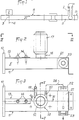
- Fig. 1 schematically shows an apparatus for subjecting a chemical reaction by a wet process to a compound placed in a container 1 into which is also introduced at least one specific reagent.
- the apparatus comprises a microwave generator 2 comprising an antenna 3 emitting, from an emissive plane 4, microwaves in an application cavity 5 in which the container 1 must be placed.
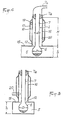
- the container 1, as shown in FIG. 4, is made of glass to include, at its base, a retention capacity 6 of at least semi-spherical shape and extended by a neck 7 of great length, of constant cylindrical section.
- the container 7 is shaped in such a way that the capacity 6 is similar to a substantially spherical volume, such as a bulb, whose diameter D, taken perpendicular to the axis of the neck 7, is greater than that d of the last.
- the container 1 could also be made, for example, of polycarbonate and have a different shape, depending on the nature of the compound and the chemical reaction to be subjected to it.
- the container 1 could be cylindrical with a flat bottom or semi-spherical.
- the cavity 5 is, in this case, constituted by the terminal segment 8 of a waveguide 9.
- the segment 8 comprises technical means usually used to ensure and improve the routing and propagation of the microwaves emitted by the antenna 3 in a general direction of propagation along the arrow f i .
- the segment 8, as illustrated in FIGS. 2 to 5, has, from a connection flange 10, a constant section, substantially equivalent to that of the guide 9.
- the segment 8 is, for example, constituted by a parallelepipedic envelope 11 made of stainless steel or brass.
- the envelope 11 has, in its upper horizontal wall, a circular opening 12, permanently open and whose diameter is equal, apart from play, to the diameter D of the capacity 6 of the container 1.
- the circular opening 12 is located at a determined distance from the emissive plane 4, so that its vertical axis corresponds, substantially, to a zone of formation of a belly by the waves emitted by the antenna 3 and propagating in the direction of the arrow f l .
- the envelope 11 is provided with a tuning device 13 placed between the flange 10 and the opening 12.
- the tuning device 13 consists of two metal rods 14 carried, in an adjustable manner, by the upper wall 15 of the segment 8 to extend in a direction perpendicular to the longitudinal axis of the envelope 11 inside the latter, being both placed on the longitudinal axis of the segment.
- Figs. 4 and 5 show an important constructive characteristic of the invention according to which the cavity 5 has, at least in line with the opening 12, a height h corresponding substantially to excess in diameter D.
- the capacity 6 of the container can be placed inside the cavity 5 by being introduced through the opening 12, while the neck 7 rises above the wall 15.
- the opening 12 is bordered by a tubular chimney 16 of cylindrical shape, of constant section.
- the chimney 16 rises over a height H chosen as a function of the section of the opening 12 and of the frequency of emission of the microwaves, so as to constitute an absorption barrier opposing the propagation of these microwave outside the cavity 5.
- H a height chosen as a function of the section of the opening 12 and of the frequency of emission of the microwaves, so as to constitute an absorption barrier opposing the propagation of these microwave outside the cavity 5.
- H height chosen as a function of the section of the opening 12 and of the frequency of emission of the microwaves, so as to constitute an absorption barrier opposing the propagation of these microwave outside the cavity 5.
- H height chosen as a function of the section of the opening 12 and of the frequency of emission of the microwaves, so as to constitute an absorption barrier opposing the propagation of these microwave outside the cavity 5.
- This excess measurement is provided for adaptation
- the chimney 16 is surrounded by a sleeve 17 delimiting an annular chamber 18.
- the sleeve 17 comprises two pipes 19 and 20 for connection to a circuit for circulating an appropriate fluid, making it possible to regulate the temperature of the chimney and, by Consequently, that of the neck 7 as a function of the chemical reaction to be carried out.
- the temperature control fluid is, for example, constituted by water.
- the end of the envelope 11, opposite the flange 10 relative to the chimney 7, is preferably occupied by a chamber 21 water trap.
- This chamber is in relation to two fittings 22 and 23 attached to the lateral faces of the casing 11 for the connection with a water circulation circuit.
- the connector 22, corresponding to the inlet is connected by a pipe 24 to the outlet pipe 20 of the annular chamber 18.
- the chamber 21 could be replaced by a dry absorber or, possibly again, suppressed provided that the standing wave rate during application remains admissible by the generator and does not significantly shorten its life.
- Microwave oven Type LMI, Process interrupted due to the departure of sulfuric acid and model LAB 607, 600 W) obtaining a carbonaceous mass. Pollution of the oven and
- Microwave oven Reaction stops after 15 min (heating time + cooling time) because vaporization of H Z S0 4 . Obtaining a yellowish solution. N 15.2%. Pollution of the enclosure.
- Microwave oven 50 min including exposure time + handling time + cooling time. Driving difficulties due to the heating power and the release of nitrous vapors. Add more than 8 ml of nitric acid.
- 45 min invention comprising six successive 100 W oxidation and 120 W elimination sequences. Addition of more than 8 ml of nitric acid. No pollution.
- Microwave oven Exposure time 6 minutes 30 seconds. Constant monitoring (presence of mosses). Clear liquid. N + 13%.
- Microwave oven Heating time + cooling time 10 min. End of reaction time> 10 min. Very difficult to control reaction (very short heating time) due to the boiling of the acid mixture. Losses and pollution.
- Microwave oven The boiling of the medium is so rapid ( ⁇ 10 seconds) that it was not possible, despite supervision, to avoid the overflow of the reagents and the loss of part of the sample in the oven.
- Another advantage of the object of the invention lies in the fact that the presence of the annular chamber 17 makes it possible to modulate and regulate the temperature of the neck 7, despite the rise in temperature of the product placed in the bulb 6. This allows favor, depending on the type of reaction, either a cooling favorable to condensation of the vapors along the neck 7, or a heating of the latter in the case, in particular, of the mineralization phase by reduction to ensure the evaporation of the products of reaction, as in Example A-3. In such a case, the communication between the chamber 21 and the chamber 18 is eliminated, the chamber 18 then being placed in relation to a circuit for supplying a fluid whose temperature is regulated as a function of the reaction implemented.
- Yet another advantage lies in the fact that the open upper end of the neck is accessible and makes it possible to adapt the material specific to the reaction to be carried out, such as a refrigeration column according to examples B-2 and 3 or examples C -1 and 2.
Landscapes
- Chemical & Material Sciences (AREA)
- Electromagnetism (AREA)
- Physics & Mathematics (AREA)
- Organic Chemistry (AREA)
- Toxicology (AREA)
- General Health & Medical Sciences (AREA)
- Health & Medical Sciences (AREA)
- Chemical Kinetics & Catalysis (AREA)
- Physical Or Chemical Processes And Apparatus (AREA)
- Organic Low-Molecular-Weight Compounds And Preparation Thereof (AREA)
- Devices For Use In Laboratory Experiments (AREA)
- Investigating Or Analyzing Non-Biological Materials By The Use Of Chemical Means (AREA)
- Control Of Non-Electrical Variables (AREA)
Abstract
Description
La présente invention concerne le domaine technique de la réaction chimique de composés minéraux, organiques ou organo-métalliques.The present invention relates to the technical field of the chemical reaction of mineral, organic or organometallic compounds.
On sait qu'il est nécessaire, avant la plupart des traitements d'analyse de composés tels que ci-dessus, de procéder à une réaction chimique, par exemple une minéralisation par voie humide au moyen d'acides concentrés, comme l'acide sulfurique, l'acide nitrique, l'acide perchlorique, ou des mélanges de ces acides ou, encore, une saponification par la potasse alcoolique, une oxydation ou une réduction.It is known that it is necessary, before most of the treatments for analysis of compounds such as above, to carry out a chemical reaction, for example a mineralization by the wet route by means of concentrated acids, such as sulfuric acid. , nitric acid, perchloric acid, or mixtures of these acids or, again, saponification by alcoholic potash, oxidation or reduction.
Pour mener à bien un tel traitement d'analyse préalable, une méthode classique consiste à disposer dans un vase, par exemple du type matras, une dose de composé à analyser, ainsi que le volume complémentaire nécessaire de réactif concentré spécifique.To carry out such a preliminary analysis treatment, a conventional method consists in placing in a vase, for example of the flask type, a dose of compound to be analyzed, as well as the necessary additional volume of specific concentrated reagent.
Le vase est ensuite chauffé et surveillé en permanence par un opérateur qui a la charge de régler, périodiquement, les calories transmises au vase, pour éviter l'apparition de mousses et le débordement du produit. L'opérateur doit, également, agiter, périodiquement mais de façon fréquente, le mélange soumis à échauffement, afin d'entretenir une bonne homogénéité du composé dissous et chauffé.The vase is then heated and constantly monitored by an operator who is responsible for periodically adjusting the calories transmitted to the vase, to avoid the appearance of foam and overflowing of the product. The operator must also shake, periodically but frequently, the mixture subjected to heating, in order to maintain good homogeneity of the dissolved and heated compound.
Une telle surveillance est longue, fastidieuse et susceptible de provoquer des accidents physiques, parfois graves pour l'opérateur, par les risques d'explosion, de projections de la composition et par l'émanation de fumées et vapeurs corrosives.Such monitoring is long, tedious and capable of causing physical accidents, sometimes serious for the operator, by the risks of explosion, of projections of the composition and by the emanation of corrosive fumes and vapors.
En plus des inconvénients ci-dessus, il faut noter que la méthode ainsi appliquée ne permet pas de contrôler efficacement l'éventuel départ de fractions des produits entrant dans la composition de base et entraînées par les fumées et vapeurs qui s'échappent du col du vase. Il s'ensuit que le résultat ultérieur d'analyse s'en trouve fortement perturbé, sans qu'un moyen de contrôle ne puisse apporter une possibilité d'évaluation de l'existence et de l'importance de ce facteur négatif aléatoire.In addition to the above drawbacks, it should be noted that the method thus applied does not allow effective control of the possible departure of fractions of the products entering the basic composition and entrained by the fumes and vapors which escape from the neck of the vase. It follows that the subsequent analysis result is greatly disturbed, without a means of control being able to provide a possibility of evaluation of the existence and the importance of this random negative factor.
Pour tenter de parfaire un tel procédé, différentes propositions d'amélioration ont été développées et mises en oeuvre.In an attempt to perfect such a process, various improvement proposals have been developed and implemented.
C'est ainsi qu'on a proposé des installations mettant en oeuvre, en tant que moyen de chauffage, au lieu d'une flamme directe, une batterie de creusets à rayonnement infra-rouge dont la puissance de chacun peut être réglée en agissant sur une alimentation électrique propre. Une telle batterie de creusets est associée à un collecteur de fumées commun à l'ensemble des creusets et relié à un groupe de pompage.Thus, installations have been proposed using, as a means of heating, instead of a direct flame, a battery of crucibles with infrared radiation, the power of each of which can be adjusted by acting on a clean power supply. Such a battery of crucibles is associated with a smoke collector common to all of the crucibles and connected to a pumping group.
Si ces modifications ont apporté une certaine amélioration, en revanche, elles ne permettent pas de régler les problèmes de la surveillance permanente, de l'agitation et de l'incertitude des résultats obtenus, étant donné que ces trois facteurs sont toujours fonction de l'attention permanente d'un ou de plusieurs opérateurs.While these modifications have brought some improvement, however, they do not solve the problems of continuous monitoring, agitation and uncertainty of the results obtained, since these three factors are always a function of the permanent attention of one or more operators.
Par ailleurs, il doit être considéré que la conduite d'une telle installation exige un savoir-faire certain. En effet, le réglage de la puissance de chauffe de chaque creuset doit être évalué en fonction de l'inertie thermique d'un tel appareil et exige, par conséquent, une très bonne expérience pour apprécier le facteur d'anticipation à retenir pour l'augmentation mais aussi pour l'abaissement de la température imposée à un échantillon.Furthermore, it must be considered that the operation of such an installation requires certain know-how. Indeed, the adjustment of the heating power of each crucible must be evaluated according to the thermal inertia of such a device and therefore requires very good experience to assess the anticipation factor to be retained for the increase but also for lowering the temperature imposed on a sample.
Toujours dans le but d'améliorer un tel procédé de traitement préalable d'analyse, on a proposé d'utiliser, en tant que générateur de chaleur, un four micro-ondes muni d'une prise d'aspiration des fumées et vapeurs.Still with the aim of improving such a method of preliminary analysis treatment, it has been proposed to use, as a heat generator, a microwave oven provided with a suction outlet for fumes and vapors.
Le brevet américain 4 080 168 enseigne une telle proposition et préconise la mise en oeuvre d'un four micro-ondes dans la cavité duquel est placé un vase contenant l'échantillon à traiter.US Patent 4,080,168 teaches such a proposal and recommends the use of a microwave oven in the cavity of which is placed a vase containing the sample to be treated.
Cette technique présente des avantages certains, car l'application de micro-ondes permet une répartition quasi uniforme de l'énergie et donc un chauffage à coeur du composé à traiter. Pour les mêmes raisons, une telle technique permet de briser les mousses qui se développent avec la technique précédente lors de la montée en température du composé. Une surveillance permanente de l'évolution du traitement n'est donc plus nécessaire théoriquement et libère ainsi un opérateur de cet aspect fastidieux et dangereux de la méthode antérieure.This technique has certain advantages, because the application of microwaves allows an almost uniform distribution of energy and therefore heating the compound to be treated. For the same reasons, such a technique makes it possible to break down the foams which develop with the previous technique during the rise in temperature of the compound. A permanent monitoring of the evolution of the treatment is therefore no longer theoretically necessary and thus frees an operator from this tedious and dangerous aspect of the previous method.
En outre, un four micro-ondes est connu pour ses propriétés d'absence d'inertie thermique, ce qui permet de régler plus précisément l'énergie transmise à l'échantillon.In addition, a microwave oven is known for its properties of absence of thermal inertia, which makes it possible to more precisely regulate the energy transmitted to the sample.
On s'est, cependant, aperçu qu'un tel appareil ne donnait pas encore satisfaction. On a, en effet, constaté qu'un certain nombre de produits ne pouvaient pas être traités, en raison, notamment, de l'ébullition rapide du réactif additionné.However, we realized that such a device was not yet satisfactory. It has in fact been found that a certain number of products cannot be treated, due, in particular, to the rapid boiling of the added reagent.
Dans d'autres cas, on a constaté que la conduite du procédé de minéralisation ne pouvait pas être menée à bien sans intervention fréquente d'un opérateur, comme dans le cas de chauffage par rampe traditionnelle, en raison du fait qu'un tel four ne permet pas de contrôler précisément l'énergie appliquée. Dans ce cas, une telle technique est alors affectée des mêmes inconvénients que ceux rappelés ci-dessus.In other cases, it has been found that the conduct of the mineralization process could not be carried out without frequent intervention by an operator, as in the case of traditional ramp heating, due to the fact that such an oven does not allow precise control of the applied energy. In this case, such a technique is then affected by the same drawbacks as those mentioned above.
Par ailleurs, on a constaté aussi que les résultats d'analyse ultérieure n'étaient pas toujours précis et faisaient intervenir un facteur d'incertitude non négligeable pour certains produits, voire rédhibitoire pour d'autres. Plus précisément, on a pu constater une perte de certains produits, perte mise au compte d'un entraînement de fractions de ces produits par les fumées et vapeurs importantes, par évaporation sélective et/ou par effet de primage.Furthermore, it was also found that the results of subsequent analysis were not always precise and involved a non-negligible factor of uncertainty for certain products, even prohibitive for others. More precisely, it has been possible to observe a loss of certain products, loss due to the entrainment of fractions of these products by the significant fumes and vapors, by selective evaporation and / or by priming effect.
En raison de la forte vaporisation, on a aussi constaté une forte pollution de la cavité d'application exigeant une opération de nettoyage des parois de cette cavité après chaque réaction et avant de procéder au traitement subséquent d'un échantillon de même nature ou non.Due to the high vaporization, it has also been observed that the application cavity is highly polluted, requiring an operation to clean the walls of this cavity after each reaction and before proceeding with the subsequent treatment of a sample of the same nature or not.
La forte évaporation du ou des réactifs pose, par ailleurs, un problème d'ordre pratique difficile à résoudre. Dans le cas le plus fréquent où l'opérateur doit nécessairement intervenir pour, périodiquement, extraire et replacer l'échantillon dans la cavité d'application, on conçoit que la préhension du vase ne doit poser aucun problème. Or, en raison de la forte évaporation, la face extérieure de la paroi du vase est recouverte d'une couche de gouttelettes qui risquent d'avoir des conséquences graves sur l'environnement lorsque le réactif utilisé est un acide, comme dans le cas de minéralisation ou d'oxydation.The high evaporation of the reagent (s) also poses a practical problem which is difficult to solve. In the most frequent case where the operator must necessarily intervene to periodically extract and replace the sample in the application cavity, it is understood that the gripping of the vase should not pose any problem. However, due to the high evaporation, the outer face of the wall of the vase is covered with a layer of droplets which may have serious consequences on the environment when the reagent used is an acid, as in the case of mineralization or oxidation.
La forte évaporation a aussi pour résultat négatif de développer, à l'intérieur de la cavité où le récipient est placé, un brouillard de vapeur s'opposant à toute appréciation visuelle du déroulement de la réaction en cours.The strong evaporation also has the negative result of developing, inside the cavity where the container is placed, a mist of vapor opposing any visual appreciation of the progress of the reaction in progress.
La mise en oeuvre de la technique préconisée par ce brevet US ne peut donc pas être envisagée pratiquement dans le domaine industriel. Ceci a d'ailleurs été perçu depuis déjà quelques temps, puisque la publication BARRETT, DAVIDOWSKI, PENARO, COPELAND, anal. Chem. 1978-50, 1021 a fait paraître une technique améliorée et dérivée de l'enseignement de ce brevet US et visant à réduire, sans les supprimer, les inconvénients découlant de la forte vaporisation.The implementation of the technique recommended by this US patent cannot therefore be envisaged practically in the industrial field. This has also been seen for some time, since the publication BARRETT, DAVIDOWSKI, PENARO, COPELAND, anal. Chem. 1978-50, 1021 published an improved technique derived from the teaching of this US patent and aimed at reducing, without eliminating them, the drawbacks arising from the strong vaporization.
Une autre proposition a aussi été faite par la publication GB-A-2 081 442 dans laquelle un four micro-ondes délimite une cavité d'application apte à contenir plusieurs récipients suspendus par leurs cols. Les ouvertures supérieures des récipients s'ouvrent dans un collecteur de fumées et vapeurs qui sont aspirées extérieurement.Another proposal was also made by publication GB-A-2 081 442 in which a microwave oven delimits an application cavity capable of containing several containers suspended by their necks. The upper openings of the containers open in a smoke and vapor collector which are sucked in externally.
Une telle proposition peut être considérée comme résolvant uniquement le problème de la pollution de la cavité d'application et de la surface extérieure des récipients. Par contre, tous les autres problèmes énumérés ci-avant subsistent.Such a proposal can be considered as solving only the problem of pollution of the application cavity and of the external surface of the containers. However, all the other problems listed above remain.
La présente invention a pour objet un nouvel appareil de réaction chimique par voie humide, mettant toujours en oeuvre l'application de micro-ondes, mais dont la structure particulière permet justement de supprimer les inconvénients des méthodes actuelles et, plus précisément, de ceux attachés à la technique selon le brevet US 4 080 168.The subject of the present invention is a new wet chemical reaction apparatus, still employing the application of microwaves, but the particular structure of which precisely allows the drawbacks of the current methods and, more precisely, of those attached, to be eliminated. to the technique according to US Patent 4,080,168.
Les caractéristiques structurelles de l'appareil selon l'invention ont, par ailleurs, permis de constater l'obtention de résultats surprenants dans la conduite du traitement de minéralisation de certains produits.The structural characteristics of the device according to the invention have, moreover, made it possible to note the obtaining of surprising results in the conduct of the mineralization treatment of certain products.
L'appareil de réaction chimique par voie humide conforme à l'invention est caractérisé en ce qu'il comprend une cavité d'application :
- - présentant dans son dessus une ouverture en permanence ouverte, de section égale, au jeu près, à la plus grande mesure de la capacité prise perpendiculairement à l'axe du col, afin que le récipient puisse être introduit dans la cavité par l'ouverture,
- - ayant, au moins à l'aplomb de l'ouverture, une hauteur sensiblement égale à la hauteur de la capacité,
- - et comportant une cheminée bordant l'ouverture et s'élevant sur une hauteur fonction de la fréquence d'émission des micro-ondes et de la section de passage de l'ouverture pour former une barrière d'absorption s'opposant à la propagation de micro-ondes à l'extérieur de la cavité.
- - having in its top a permanently open opening, of equal cross-section, apart from play, to the greatest extent of the capacity taken perpendicular to the axis of the neck, so that the container can be introduced into the cavity through the opening ,
- - having, at least below the opening, a height substantially equal to the height of the capacity,
- - And comprising a chimney bordering the opening and rising over a height depending on the frequency of emission of the microwaves and the passage section of the opening to form an absorption barrier opposing the propagation outside the cavity.
Diverses autres caractéristiques ressortent de 'la description faite ci-dessous en référence aux dessins annexés qui montrent, à titre d'exemple non limitatif, une forme de réalisation de l'objet de l'invention.
- La fig. 1 est une vue schématique illustrant un appareil faisant application des moyens de l'invention.
- La fig. 2 est une élévation longitudinale de l'un des éléments constitutifs de l'invention.
- La fig. 3 est une vue de dessus prise selon la ligne III-111 de la fig. 2.
- Fig. 1 is a schematic view illustrating an apparatus applying the means of the invention.
- Fig. 2 is a longitudinal elevation of one of the constituent elements of the invention.
- Fig. 3 is a top view taken along line III-111 of FIG. 2.
La fig. 4 et la fig. 5 sont des coupes-élévations prises, respectivement, selon les lignes IV-IV et V-V de la fig. 3.Fig. 4 and fig. 5 are sectional elevations taken, respectively, along lines IV-IV and V-V of FIG. 3.
La fig. 1 montre, de façon schématique, un appareil destiné à soumettre à une réaction chimique par voie humide un composé disposé dans un récipient 1 dans lequel on introduit, également, au moins un réactif spécifique.Fig. 1 schematically shows an apparatus for subjecting a chemical reaction by a wet process to a compound placed in a container 1 into which is also introduced at least one specific reagent.
L'appareil comprend un générateur de micro-ondes 2 comportant une antenne 3 émettant, à partir d'un plan émissif 4, des micro-ondes dans une cavité d'application 5 dans laquelle le récipient 1 doit être placé.The apparatus comprises a microwave generator 2 comprising an
Selon l'invention, le récipient 1, tel que représenté à la fig. 4, est réalisé en verre pour comporter, à sa base, une capacité de rétention 6 de forme au moins semi-sphérique et prolongée par un col 7 de grande longueur, de section cylindrique constante. De préférence, le récipient 7 est conformé de telle manière que la capacité 6 s'apparente à un volume sensiblement sphérique, tel qu'un bulbe, dont le diamètre D, pris perpendiculairement à l'axe du col 7, est supérieur à celui d de ce dernier. Le récipient 1 pourrait aussi être réalisé, par exemple, en polycarbonate et présenter une forme différente, en fonction de la nature du composé et de la réaction chimique à lui faire subir. Ainsi, le récipient 1 pourrait être cylindrique à fond plat ou semi-sphérique.According to the invention, the container 1, as shown in FIG. 4, is made of glass to include, at its base, a
La cavité 5 est, dans le cas présent, constituée par le segment terminal 8 d'un guide d'ondes 9. Le segment 8 comporte des moyens techniques habituellement mis en oeuvre pour assurer et améliorer le cheminement et la propagation des micro-ondes émises par l'antenne 3 dans une direction générale de propagation selon la flèche fi. Le segment 8, tel qu'illustré par les fig. 2 à 5, présente, à partir d'une bride de raccordement 10, une section constante, sensiblement équivalente à celle du guide 9. Le segment 8 est, par exemple, constitué par une enveloppe parallélépipédique 11 réalisée en acier inoxydable ou en laiton. L'enveloppe 11 comporte, dans sa paroi horizontale supérieure, une ouverture 12 circulaire, en permanence ouverte et dont le diamètre est égal, au jeu près, au diamètre D de la capacité 6 du récipient 1. L'ouverture circulaire 12 est située à une distance déterminée du plan émissif 4, de manière que son axe vertical corresponde, sensiblement, à une zone de formation d'un ventre par les ondes émises par l'antenne 3 et se propageant dans le sens de la flèche fl. Afin d'assurer cette correspondance, l'enveloppe 11 est munie d'un dispositif d'accord 13 placé entre la bride 10 et l'ouverture 12. De préférence, le dispositif d'accord 13 est constitué par deux tiges métalliques 14 portées, de façon réglable, par la paroi supérieure 15 du segment 8 pour s'étendre selon une direction perpendiculaire à l'axe longitudinal de l'enveloppe 11 à l'intérieur de cette dernière, en étant placées toutes les deux sur l'axe longitudinal du segment.The
Les fig. 4 et 5 montrent une caractéristique constructive importante de l'invention selon laquelle la cavité 5 présente, au moins à l'aplomb de l'ouverture 12, une hauteur h correspondant sensiblement par excès au diamètre D. Ainsi, seule la capacité 6 du récipient peut être disposée à l'intérieur de la cavité 5 en étant introduite par l'ouverture 12, alors que le col 7 s'élève au-dessus de la paroi 15.Figs. 4 and 5 show an important constructive characteristic of the invention according to which the
L'ouverture 12 est bordée par une cheminée tubulaire 16 de forme cylindrique, de section constante. La cheminée 16 s'élève sur une hauteur H choisie en fonction de la section de l'ouverture 12 et de la fréquence d'émission des micro-ondes, de manière à constituer une barrière d'absorption s'opposant à la propagation de ces micro-ondes à l'extérieur de la cavité 5. Dans tous les cas, il est prévu de réaliser le récipient 1 de telle sorte que le col 7 présente une longueur supérieure à la dimension H. Cette mesure excédentaire est prévue pour l'adaptation d'une coupelle ou analogue 7a de suspension et de centrage du récipient par rapport à la cheminée 16. Ceci permet de faire coïncider l'axe du vase et l'axe de la cheminée et de placer ainsi précisément la capacité 6 en coïncidence avec la position théorique du ventre de l'onde devant se développer au droit de l'ouverture 12. La coupelle 7a sert, également, de siège d'appui à un capuchon ou couvercle 7b relié à un groupe de pompage des fumées et vapeurs.The
La cheminée 16 est entourée par un manchon 17 délimitant une chambre annulaire 18. Le manchon 17 comporte deux tubulures 19 et 20 de raccordement à un circuit de mise en circulation d'un fluide approprié, permettant de réguler la température de la cheminée et, par conséquent, de celle du col 7 en fonction de la réaction chimique à conduire. Le fluide de régulation de température est, par exemple, constitué par de l'eau.The
L'extrémité de l'enveloppe 11, opposée à la bride 10 par rapport à la cheminée 7, est, de préférence, occupée par une chambre 21 piège à eau. Cette chambre est en relation avec deux raccords 22 et 23 rapportés sur les faces latérales de l'enveloppe 11 pour la liaison avec un circuit de circulation d'eau. Selon une disposition préférée de l'invention, le raccord 22, correspondant à l'admission, est relié par une canalisation 24 à la tubulure 20 de sortie de la chambre annulaire 18.The end of the
La chambre 21 pourrait être remplacée par un absorbeur sec ou, éventuellement encore, supprimée à condition que le taux d'ondes stationnaires en cours d'application reste admissible par le générateur et n'abrège pas de façon sensible sa durée de vie.The
La mise en oeuvre des caractéristiques structurelles ci-dessus a permis d'éliminer les inconvénients des solutions techniques antérieures et d'obtenir, dans la conduite des réactions chimiques diverses, des résultats surprenants, voire inattendus, en mettant en oeuvre les caractéristiques ci-dessous chiffrées concernant un exemple d'appareil selon l'invention.

Les exemples ci-dessous donnent des résultats obtenus avec un tel appareil et fournissent les résultats enregistrés pour des mêmes échantillons de produits, avec les méthodes antérieures connues.The examples below give results obtained with such an apparatus and provide the results recorded for the same product samples, with the known prior methods.
A - Réaction de minéralisation.A - Mineralization reaction.
- - Huile succinimide C 5935 fabriquée par la société OROGIL 200 mg- Succinimide oil C 5935 manufactured by the company OROGIL 200 mg
- - Acide sulfurique 4 ml- Sulfuric acid 4 ml
- - Catalyseur Kjeldahl 3g- Kjeldahl catalyst 3g
Rampe infrarouge 6 heures.6 hour infrared ramp.
Four micro-ondes (Type LMI, Procédé interrompu en raison du départ de l'acide sulfurique et de modèle LAB 607, 600 W) l'obtention d'une masse charbonneuse. Pollution du four et duMicrowave oven (Type LMI, Process interrupted due to the departure of sulfuric acid and model LAB 607, 600 W) obtaining a carbonaceous mass. Pollution of the oven and
Invention 1 heure à 120 W ou 18 min à 200 W. Absence de pollution.Invention 1 hour at 120 W or 18 min at 200 W. No pollution.
- - Monochlorhydrate de LYSINE 50 mg- LYSINE hydrochloride 50 mg
- - Acide sulfurique 4 ml- Sulfuric acid 4 ml
- - Catalyseur Kjeldahl 3 g- Kjeldahl catalyst 3 g
Rampe infrarouge > 1 heure.Infrared ramp> 1 hour.
Four micro-ondes Arrêt de la réaction après 15 min (Temps chauffage + temps refroidissement) car vaporisation de HZS04. Obtention d'une solution jaunâtre. N = 15,2 %. Pollution de l'enceinte.Microwave oven Reaction stops after 15 min (heating time + cooling time) because vaporization of H Z S0 4 . Obtaining a yellowish solution. N = 15.2%. Pollution of the enclosure.
Invention 28 min comprenant 2 min à 60 W et 26 min à 120 W. Solution limpide et incolore. N = 15,2 %. Absence de pollution.Invention 28 min including 2 min at 60 W and 26 min at 120 W. Clear and colorless solution. N = 15.2%. No pollution.
- - PVC n° 140 fabriqué par RHONE-POULENC 210 mg- PVC n ° 140 manufactured by RHONE-POULENC 210 mg
-
- Acide sulfurique 5 ml-
Sulfuric acid 5 ml - - Acide nitrique 2 ml- Nitric acid 2 ml
Rampe infrarouge 16 heures. Ajout de plus de 10 ml d'acide nitrique.16 hour infrared ramp. Addition of more than 10 ml of nitric acid.
Four micro-ondes 50 min comprenant le temps d'exposition + le temps de manipulation + le temps de refroidissement. Difficultés de conduite dues à la puissance de chauffe et au dégagement de vapeurs nitreuses. Ajout de plus de 8 ml d'acide nitrique.Microwave oven 50 min including exposure time + handling time + cooling time. Driving difficulties due to the heating power and the release of nitrous vapors. Add more than 8 ml of nitric acid.
Invention 45 min comprenant six séquences successives d'oxydation à 100 W et d'élimination à 120 W. Ajout de plus de 8 ml d'acide nitrique. Absence de pollution.45 min invention comprising six successive 100 W oxidation and 120 W elimination sequences. Addition of more than 8 ml of nitric acid. No pollution.
- - Phosphonate 60 mg- Phosphonate 60 mg
-
- Acide sulfurique 3 ml-
Sulfuric acid 3 ml - - Acide nitrique 0,2 ml- 0.2 ml nitric acid
- - Eau oxygénée 0,2 ml- 0.2 ml oxygenated water
Rampe infrarouge 4 heures. P = 14,79 %.4 hour infrared ramp. P = 14.79%.
Four micro-ondes 33 min. P = 15,2 %. Apparition d'un brouillard acide très épais et pollution.Microwave oven 33 min. P = 15.2%. Very thick acid fog and pollution appear.
Invention 40 min - 120 W. P = 14,78 %. Absence de pollution.Invention 40 min - 120 W. P = 14.78%. No pollution.
- - Protéine d'oeuf 50 mg- Egg protein 50 mg
- - Acide sulfurique 4 ml- Sulfuric acid 4 ml
- - Catalyseur Kjeldahl 3 g- Kjeldahl catalyst 3 g
Rampe infrarouge 1 heure. N = 13 %.1 hour infrared ramp. N = 13%.
Four micro-ondes Temps d'exposition : 6 minutes 30 secondes. Surveillance constante (présence de mousses). Liquide clair. N + 13 %.Microwave oven Exposure time: 6 minutes 30 seconds. Constant monitoring (presence of mosses). Clear liquid. N + 13%.
Invention 9 min à 120 W (initial 80 W) ou 6 min à 200 W. N = 13 %. Absence de mousse. Pas de surveillance.
B. ― Réaction d'oxydation.B. - Oxidation reaction.
- - Hastelloy B 320 mg- Hastelloy B 320 mg
-
- Eau régale 5 ml-
Aqua regia 5 ml
Rampe infrarouge 1 à plusieurs jours. Réaction souvent incomplète.Infrared ramp 1 to several days. Often incomplete reaction.
Four micro-ondes Temps de chauffe + refroidissement = 10 min. Temps fin de réaction > 10 min. Réaction très difficile à contrôler (temps de chauffage très court) en raison de l'ébullition du mélange acide. Pertes et pollution.Microwave oven Heating time + cooling time = 10 min. End of reaction time> 10 min. Very difficult to control reaction (very short heating time) due to the boiling of the acid mixture. Losses and pollution.
Invention 12 min - 55 W. Attaque complète. Absence de pollution.
Mesure de la D. C. O. (Demande chimique en oxygène) selon la norme française NF 90 101. Cette norme précise que la réaction doit être réalisée à reflux durant 2 heures, à l'aide d'un réfrigérant (pour éviter les pertes de substances oxydables volatiles)
- - Solution d'urée à 1,2 g/I 1 ml
- - Réactifs selon norme soit : sulfate mercurique 100 mg acide sulfurique, AgNO3 1 cm3 K2Cr2O7 à 0,25
N 3 cm3
- - Urea solution at 1.2 g / I 1 ml
- - Reagents according to standard either: mercuric sulfate 100 mg sulfuric acid, AgNO 3 1 cm 3 K 2 Cr 2 O 7 at 0.25
N 3 cm 3
Réaction selon la norme DCO = 0 mg/l (Temps = 2 heures).Reaction according to COD standard = 0 mg / l (Time = 2 hours).
Rampe infrarouge DCO = 0 mg/l (Temps = 2 heures).Infrared ramp COD = 0 mg / l (Time = 2 hours).
Four micro-ondes L'ébullition du milieu est tellement rapide (< 10 secondes) qu'il n'a pas été possible, malgré surveillance, d'éviter le débordement des réactifs et la perte d'une partie de l'échantillon dans le four.Microwave oven The boiling of the medium is so rapid (<10 seconds) that it was not possible, despite supervision, to avoid the overflow of the reagents and the loss of part of the sample in the oven.
Dans ce type de matériel il est impossible d'appliquer la norme en raison de l'impossibilité de faire intervenir un réfrigérant. Invention DCO = 0 mg/l (Temps = 15 minutes). Respect de la norme, montage du réfrigérant aisé en dehors de la cheminée. Absence de débordement par contrôle de la puissance.In this type of equipment it is impossible to apply the standard due to the impossibility of involving a refrigerant. COD invention = 0 mg / l (Time = 15 minutes). Compliance with the standard, easy installation of the refrigerant outside the chimney. Absence of overflow by power control.
Mesure de la DCO.COD measurement.
- - Effluent de la station d'épuration RHONE POULENC ST FONS (rejets 5019) 0,25 ml- Effluent from the RHONE POULENC ST FONS treatment plant (rejects 5019) 0.25 ml
-
- Réactifs selon norme soit : sulfate mercurique 100 mg acide sulfurique, AgN03 1 cm3 K2Cr207 à 0,25 N 3 cm3 - Reagents according to standard either: mercuric sulfate 100 mg sulfuric acid, AgN0 3 1 cm 3 K 2 Cr 2 0 7 at 0.25
N 3 cm 3 - Réaction selon la forme DCO = 4 500 mg/1 (Temps = 2 heures).COD form reaction = 4,500 mg / 1 (Time = 2 hours).
- Rampe infrarouge DCO = 4500 mg/I (Temps = 2 heures).Infrared ramp COD = 4500 mg / I (Time = 2 hours).
- Four micro-ondes L'ébullition du milieu est tellement rapide (< 10 secondes) qu'il n'a pas été possible, malgré surveillance, d'éviter le débordement des réactifs et la perte d'une partie de l'échantillon dans le four.Microwave oven The boiling of the medium is so rapid (<10 seconds) that it was not possible, despite supervision, to avoid the overflow of the reagents and the loss of part of the sample in the oven.
- Dans ce type de matériel il est impossible d'appliquer la norme en raison de l'impossibilité de faire intervenir un réfrigérant. Invention DCO = 4550 mg/l (Temps = 15 minutes). Puissance appliquée = 100 W. Le résultat est identique après 2 heures. Respect de la norme, montage du réfrigérant aisé en dehors de la cheminée. Absence de débordement par contrôle de la puissance.In this type of equipment it is impossible to apply the standard due to the impossibility of involving a refrigerant. COD invention = 4550 mg / l (Time = 15 minutes). Applied power = 100 W. The result is identical after 2 hours. Compliance with the standard, easy installation of the refrigerant outside the chimney. Absence of overflow by power control.
C - Réaction de saponification et/ou hydrolyse.C - Saponification and / or hydrolysis reaction.
Détermination du chlore hydrolysable dans des composés chlorés (à reflux) selon la norme américaine ASTM D 2441-68.Determination of hydrolyzable chlorine in chlorinated compounds (at reflux) according to the American standard ASTM D 2441-68.
- - 1,1,1, Trichloroéthane commercialisée sous la marque « FLUKA » 48 mg- 1,1,1, Trichloroethane marketed under the brand name "FLUKA" 48 mg
-
- Soude méthanolique à 1,1 M 10 ml- 1.1 M
methanolic soda 10 ml - Réaction selon la forme ASTMASTM reaction
- (plaque chauffante ou rampe) CI = 0,30 % (1 heure)(heating plate or ramp) CI = 0.30% (1 hour)
- Four micro-ondes Différence avec la norme : on ne peut pas installer de réfrigérant. Après moins de 10 secondes d'exposition on observe une mini- explosion dans le matras avec pertes quasi totales. Absence de mesures.Microwave oven Difference from standard: you cannot install a refrigerant. After less than 10 seconds of exposure, a mini-explosion in the flask is observed with almost total losses. Absence of measures.
- Invention (selon la norme) CI = 0,38 % 8 minutes et Puissance appliquée = 40 W.Invention (according to standard) CI = 0.38% 8 minutes and Power applied = 40 W.
- - Mélange de 1,2,3 et 1,2,4 trichlobenzène RP TRI-A n° EC 80-2 4 g- Mixture of 1,2,3 and 1,2,4 trichlobenzene RP TRI-A n ° EC 80-2 4 g
-
- Soude méthanolique 0,1 M 10 ml- 0.1 M
methanolic soda 10 ml - Réaction selon la norme ATSM (plaque chauffante ou rampe) CI = 5 ppm (1 heure).Reaction according to ATSM standard (heating plate or ramp) CI = 5 ppm (1 hour).
- Four micro-ondes Différence avec la norme : on ne peut pas installer de réfrigérant. Après moins de 10 secondes d'exposition on observe une mini- explosion dans le matras avec pertes quasi totales. Absence de mesures.Microwave oven Difference from standard: you cannot install a refrigerant. After less than 10 seconds of exposure, a mini-explosion in the flask is observed with almost total losses. Absence of measures.
- Invention (selon la norme) CI = 3 ppm 80 W - 8 minutes. Résultat identique 80 W - 60 min temps de la norme.Invention (according to standard) CI = 3 ppm 80 W - 8 minutes. Identical result 80 W - 60 min standard time.
La comparaison des résultats ci-dessus permet de constater que la mise en oeuvre des caractéristiques structurelles de l'appareil selon l'invention assure :
- - une absence totale de pollution du matériel selon l'invention,
- - un procédé propre permettant les manipulations sans précautions particulières,
- - une possibilité de traitement de produits qui, jusqu'à présent, ne pouvaient être traités qu'avec une durée de réaction particulièrement longue, selon la technique traditionnelle ou ne pouvaient l'être avec la technique selon le brevet US n° 4 080 168,
- - un gain de temps de traitement notable, voire très important, par rapport à la méthode traditionnelle,
- - un gain de puissance et, par conséquent, de consommation d'énergie élevé par rapport aux techniques traditionnelles,
- - une possibilité de travailler à reflux selon l'exigence de normes nationales ou internationales.
- a total absence of pollution of the material according to the invention,
- - a clean process allowing handling without special precautions,
- - a possibility of treatment of products which, until now, could only be treated with a particularly long reaction time, according to the traditional technique or could not be treated with the technique according to US Patent No. 4,080,168 ,
- - a significant, even very significant, gain in processing time compared to the traditional method,
- - a gain in power and, consequently, in high energy consumption compared to traditional techniques,
- - a possibility of working at reflux according to the requirement of national or international standards.
Un autre avantage de l'objet de l'invention réside dans le fait que la présence de la chambre annulaire 17 permet de moduler et de réguler la température du col 7, malgré la montée en température du produit placé dans le bulbe 6. Ceci permet de favoriser, selon le type de réaction, soit un refroidissement favorable à une condensation des vapeurs le long du col 7, soit un réchauffement de ce dernier dans le cas, notamment, de phase de minéralisation par réduction pour assurer l'évaporation des produits de réaction, comme dans l'exemple A-3. Dans un tel cas, la communication entre la chambre 21 et la chambre 18 est supprimée, la chambre 18 étant alors placée en relation avec un circuit d'apport d'un fluide dont la température est régulée en fonction de la réaction mise en oeuvre.Another advantage of the object of the invention lies in the fact that the presence of the
· Un autre avantage encore réside dans le fait que l'extrémité supérieure ouverte du col est accessible et permet d'adaptation du matériel spécifique à la réaction à conduire, comme une colonne de réfrigération selon les exemples B-2 et 3 ou les exemples C-1 et 2.Yet another advantage lies in the fact that the open upper end of the neck is accessible and makes it possible to adapt the material specific to the reaction to be carried out, such as a refrigeration column according to examples B-2 and 3 or examples C -1 and 2.
L'invention n'est pas limitée à l'exemple décrit et représenté, car diverses modifications peuvent y être apportées sans sortir de son cadre.The invention is not limited to the example described and shown, since various modifications can be made thereto without departing from its scope.
Claims (9)
Priority Applications (1)
| Application Number | Priority Date | Filing Date | Title |
|---|---|---|---|
| AT85420033T ATE45457T1 (en) | 1984-03-02 | 1985-02-26 | DEVICE FOR CHEMICAL REACTION OF DIFFERENT CHEMICALS BY WET PROCESS. |
Applications Claiming Priority (2)
| Application Number | Priority Date | Filing Date | Title |
|---|---|---|---|
| FR8403496 | 1984-03-02 | ||
| FR8403496A FR2560529B1 (en) | 1984-03-02 | 1984-03-02 | APPARATUS FOR WET CHEMICAL REACTION OF VARIOUS PRODUCTS |
Publications (2)
| Publication Number | Publication Date |
|---|---|
| EP0155893A1 EP0155893A1 (en) | 1985-09-25 |
| EP0155893B1 true EP0155893B1 (en) | 1989-08-09 |
Family
ID=9301774
Family Applications (1)
| Application Number | Title | Priority Date | Filing Date |
|---|---|---|---|
| EP85420033A Expired EP0155893B1 (en) | 1984-03-02 | 1985-02-26 | Device for chemical reaction of various chemicals by wet method |
Country Status (7)
| Country | Link |
|---|---|
| US (1) | US4681740A (en) |
| EP (1) | EP0155893B1 (en) |
| JP (1) | JPH0690192B2 (en) |
| AT (1) | ATE45457T1 (en) |
| AU (1) | AU581879B2 (en) |
| DE (1) | DE3572291D1 (en) |
| FR (1) | FR2560529B1 (en) |
Families Citing this family (35)
| Publication number | Priority date | Publication date | Assignee | Title |
|---|---|---|---|---|
| US4882286A (en) * | 1986-06-13 | 1989-11-21 | Cem Corporation | Digestion apparatus useful for a kjeldahl method |
| US4946797A (en) * | 1986-06-13 | 1990-08-07 | Cem Corporation | Microwave-based Kjeldahl method |
| US4851630A (en) * | 1988-06-23 | 1989-07-25 | Applied Science & Technology, Inc. | Microwave reactive gas generator |
| FR2643829B1 (en) * | 1989-03-06 | 1994-04-01 | Prolabo | WET CHEMICAL REACTION APPARATUS HAVING A CHIMNEY PROVIDED WITH A MICROWAVE PROPAGATION BARRIER |
| SE9002117L (en) * | 1990-06-14 | 1991-08-26 | Nils Elander | MICROWAVE DEVICE FOR TREATMENT OF PRECESSIVE LIQUID |
| AU649770B2 (en) * | 1991-01-25 | 1994-06-02 | Societe Prolabo | Apparatus for simultaneous treatment, in a moist medium, on a plurality of samples, and utilisation of the said apparatus |
| DE4114525C2 (en) * | 1991-02-19 | 1996-05-15 | Mls Gmbh | Device for triggering and / or promoting chemical and / or physical pressure reactions |
| DE4143541C2 (en) * | 1991-02-19 | 1999-03-04 | Mls Gmbh | High pressure reaction appts. for microwave-assisted reaction |
| US5417924A (en) * | 1991-02-27 | 1995-05-23 | Societe Prolabo | Apparatus connectible to a receptacle for condensing fumes generated during chemical reactions |
| FR2673118B1 (en) * | 1991-02-27 | 1994-03-04 | Prolabo | DEVICE ADAPTABLE TO A CONTAINER, PARTICULARLY FOR CHEMICAL REACTIONS, REACTOR COMPRISING SAID DEVICE AND USE THEREOF. |
| FR2685478A1 (en) * | 1991-12-23 | 1993-06-25 | Prolabo Sa | METHOD OF MEASURING THE TEMPERATURE OF A SAMPLE PLACED IN A CONTAINER OF A MICROWAVE APPLICATION APPARATUS AND APPARATUS IMPLEMENTING SAID METHOD |
| FR2697448B1 (en) * | 1992-10-30 | 1995-06-16 | Moulinex Sa | Device for conducting chemical operations. |
| US5596833A (en) * | 1994-12-16 | 1997-01-28 | Harrie; Michael R. | Fly trap container |
| US5796080A (en) * | 1995-10-03 | 1998-08-18 | Cem Corporation | Microwave apparatus for controlling power levels in individual multiple cells |
| JPH11514287A (en) * | 1995-10-03 | 1999-12-07 | シーイーエム・コーポレーション | Microwave-driven chemical processes |
| ES2281974T3 (en) * | 1998-12-17 | 2007-10-01 | Biotage Ab | MICROWAVE APPARATUS AND PROCEDURES TO CARRY OUT CHEMICAL REACTIONS. |
| EP1257356B1 (en) * | 2000-02-25 | 2004-08-18 | Biotage AB | Microwave heating apparatus |
| US6607920B2 (en) * | 2001-01-31 | 2003-08-19 | Cem Corporation | Attenuator system for microwave-assisted chemical synthesis |
| US6933482B2 (en) * | 2001-10-19 | 2005-08-23 | Personal Chemistry I Uppsala Ab | Microwave heating apparatus |
| US6630654B2 (en) * | 2001-10-19 | 2003-10-07 | Personal Chemistry I Uppsala Ab | Microwave heating apparatus |
| FR2832586A1 (en) * | 2001-11-16 | 2003-05-23 | Jouan Robotics | MICROWAVE APPLICATION APPARATUS |
| GB2397782B (en) * | 2002-03-13 | 2006-04-12 | Gopalakrishnan Srinivasan | Process and synthesizer for molecular engineering and synthesis of materials |
| US7282184B2 (en) * | 2002-04-19 | 2007-10-16 | Cem Corporation | Microwave assisted chemical synthesis instrument with controlled pressure release |
| US7144739B2 (en) * | 2002-11-26 | 2006-12-05 | Cem Corporation | Pressure measurement and relief for microwave-assisted chemical reactions |
| FR2873120B1 (en) * | 2004-07-19 | 2007-08-10 | Univ Littoral Cote D Opale | NEW PROCESS FOR SYNTHESIZING CYCLODEXTRIN DERIVATIVES USING MICROWAVE REACTOR |
| WO2007104823A1 (en) * | 2006-03-16 | 2007-09-20 | Universidad Técnica Federico Santa María | Device for extraction of organic chemical compounds with toxic properties that are present in atmospheric samples, using focused-microwave-heated solvents in open (non-pressurized) systems |
| AT504371B8 (en) * | 2006-10-03 | 2008-09-15 | Leica Mikrosysteme Gmbh | DEVICE FOR MICROWAVE-BASED PREPARATION OF SAMPLES |
| FR2922453B1 (en) * | 2007-10-17 | 2011-01-14 | Millipore Corp | DECONTAMINATION METHOD AND SYSTEM IMPLEMENTING THE SAME |
| FR2922650A1 (en) * | 2007-10-17 | 2009-04-24 | Millipore Corp | MICROBIOLOGICAL ANALYSIS MACHINE |
| FR2922651B1 (en) * | 2007-10-17 | 2010-03-19 | Millipore Corp | MICROBIOLOGICAL ANALYSIS SYSTEM |
| FR2922649B1 (en) * | 2007-10-17 | 2010-01-01 | Millipore Corp | MICROBIOLOGICAL ANALYSIS MACHINE |
| FR2922652B1 (en) * | 2007-10-17 | 2010-01-01 | Millipore Corp | MICROBIOLOGICAL ANALYSIS SYSTEM |
| US20100044210A1 (en) * | 2008-08-20 | 2010-02-25 | The Board Of Regents Of The University Of Texas System | METHOD OF DIGESTING CELLULOSE TO GLUCOSE USING SALTS AND MICROWAVE (muWAVE) ENERGY |
| EP2244529B1 (en) * | 2009-04-24 | 2019-04-03 | Anton Paar GmbH | Device for Heating a Sample by Microwave Radiation |
| EP2244530A1 (en) * | 2009-04-24 | 2010-10-27 | Anton Paar GmbH | Method and Device for Uniformly Heating a Sample by Microwave Radiation |
Family Cites Families (7)
| Publication number | Priority date | Publication date | Assignee | Title |
|---|---|---|---|---|
| US2868626A (en) * | 1956-06-18 | 1959-01-13 | Upjohn Co | Semi-micro evaporation apparatus |
| DE1912526A1 (en) * | 1969-03-12 | 1970-10-01 | Koch Dr Walter | Method and device for the formation of gaseous analysis products by heating the sample material |
| FR2128935A5 (en) * | 1971-03-09 | 1972-10-27 | Thomson Csf | |
| FR2371226A1 (en) * | 1976-11-17 | 1978-06-16 | Olivier Jean | APPLICATOR FOR SUBMITTING A MATERIAL TO WAVES |
| DE2804287A1 (en) * | 1978-02-01 | 1979-08-02 | Siemens Ag | ARRANGEMENT OF A REACTION VESSEL AND ITS TRAINING FOR A WATER ANALYZER |
| US4347216A (en) * | 1980-06-30 | 1982-08-31 | Mitsubishi Kasei Kogyo Kabushiki Kaisha | Wet sample decomposing apparatus |
| GB2122859B (en) * | 1982-07-05 | 1985-10-02 | Atomic Energy Authority Uk | Improvements in or relating to microwave heating |
-
1984
- 1984-03-02 FR FR8403496A patent/FR2560529B1/en not_active Expired
-
1985
- 1985-02-26 DE DE8585420033T patent/DE3572291D1/en not_active Expired
- 1985-02-26 AT AT85420033T patent/ATE45457T1/en not_active IP Right Cessation
- 1985-02-26 EP EP85420033A patent/EP0155893B1/en not_active Expired
- 1985-02-27 US US06/706,339 patent/US4681740A/en not_active Expired - Lifetime
- 1985-03-01 AU AU39500/85A patent/AU581879B2/en not_active Ceased
- 1985-03-02 JP JP60041762A patent/JPH0690192B2/en not_active Expired - Lifetime
Also Published As
| Publication number | Publication date |
|---|---|
| AU3950085A (en) | 1985-09-05 |
| DE3572291D1 (en) | 1989-09-14 |
| FR2560529B1 (en) | 1986-11-07 |
| US4681740A (en) | 1987-07-21 |
| FR2560529A1 (en) | 1985-09-06 |
| AU581879B2 (en) | 1989-03-09 |
| JPS60210763A (en) | 1985-10-23 |
| EP0155893A1 (en) | 1985-09-25 |
| ATE45457T1 (en) | 1989-08-15 |
| JPH0690192B2 (en) | 1994-11-14 |
Similar Documents
| Publication | Publication Date | Title |
|---|---|---|
| EP0155893B1 (en) | Device for chemical reaction of various chemicals by wet method | |
| EP0387161A1 (en) | Device for chemical reaction by wet method comprising a tubing provided with a barrier against microwave transmission | |
| EP0496684A1 (en) | Apparatus for the simultaneous wet processing of a plurality of samples, and use of the apparatus | |
| EP0249500A2 (en) | Microwave-based apparatus and kjeldahl method | |
| CA2133701C (en) | Furnace equipped with excess steam processing device | |
| US4946797A (en) | Microwave-based Kjeldahl method | |
| NL8103125A (en) | Apparatus for decomposing a wet sample. | |
| US4882286A (en) | Digestion apparatus useful for a kjeldahl method | |
| EP0772663A1 (en) | Method for recycling conditioned wood and installation for implementing the method | |
| EP0036339B1 (en) | Method for disinfecting a room and apparatus for using the method | |
| KR100354953B1 (en) | Semiconductor Wafer Drying Method and Device | |
| FR2642889A1 (en) | Process for cleaning containers contaminated with a radioactive substance | |
| FR2643789A1 (en) | Process and installation for the survival and preservation of Norway lobsters | |
| FR2945214A1 (en) | ULTRAVIOLET RAY IRRADIATION DEVICE | |
| EP1133666B1 (en) | Device for high temperature heat treatment of ligneous material | |
| JP3117671B2 (en) | Apparatus and method for concentrating chemical substances for semiconductors | |
| EP0526626A1 (en) | DEVICE ADAPTABLE TO A CONTAINER, PARTICULARLY FOR CHEMICAL REACTIONS, REACTOR COMPRISING SAID DEVICE AND USE THEREOF. | |
| EP0888814B1 (en) | Reaction support and reactor for the treatment of solid and fluid reactants subjected to a wave-shaped movement | |
| CN1222094A (en) | Device and installation for microwave extracting of organic compounds from sample | |
| JP2005179135A (en) | Extraction method of quartz glass fiber, integration method of quartz glass fiber group, and recycling method. | |
| KR102123807B1 (en) | Frying apparatus | |
| CH250363A (en) | Device for the continuous treatment of solids using fluids. | |
| FR2681431A1 (en) | Apparatus for carrying out a wet chemical reaction simultaneously on a plurality of samples and use of the said apparatus | |
| RU2777602C1 (en) | Device for ultra-high frequency heating and extraction from storage of radioactive bitumen compound | |
| FR2683736A1 (en) | Process for the treatment of acidic fumes and device for making use of the said process |
Legal Events
| Date | Code | Title | Description |
|---|---|---|---|
| PUAI | Public reference made under article 153(3) epc to a published international application that has entered the european phase |
Free format text: ORIGINAL CODE: 0009012 |
|
| AK | Designated contracting states |
Designated state(s): AT BE CH DE FR GB IT LI LU NL SE |
|
| 17P | Request for examination filed |
Effective date: 19860116 |
|
| 17Q | First examination report despatched |
Effective date: 19871016 |
|
| GRAA | (expected) grant |
Free format text: ORIGINAL CODE: 0009210 |
|
| AK | Designated contracting states |
Kind code of ref document: B1 Designated state(s): AT BE CH DE FR GB IT LI LU NL SE |
|
| REF | Corresponds to: |
Ref document number: 45457 Country of ref document: AT Date of ref document: 19890815 Kind code of ref document: T |
|
| ITF | It: translation for a ep patent filed | ||
| REF | Corresponds to: |
Ref document number: 3572291 Country of ref document: DE Date of ref document: 19890914 |
|
| GBT | Gb: translation of ep patent filed (gb section 77(6)(a)/1977) | ||
| PLBE | No opposition filed within time limit |
Free format text: ORIGINAL CODE: 0009261 |
|
| STAA | Information on the status of an ep patent application or granted ep patent |
Free format text: STATUS: NO OPPOSITION FILED WITHIN TIME LIMIT |
|
| 26N | No opposition filed | ||
| PGFP | Annual fee paid to national office [announced via postgrant information from national office to epo] |
Ref country code: LU Payment date: 19920219 Year of fee payment: 8 |
|
| PGFP | Annual fee paid to national office [announced via postgrant information from national office to epo] |
Ref country code: BE Payment date: 19920312 Year of fee payment: 8 |
|
| EPTA | Lu: last paid annual fee | ||
| PG25 | Lapsed in a contracting state [announced via postgrant information from national office to epo] |
Ref country code: LU Free format text: LAPSE BECAUSE OF NON-PAYMENT OF DUE FEES Effective date: 19930226 |
|
| ITTA | It: last paid annual fee | ||
| PG25 | Lapsed in a contracting state [announced via postgrant information from national office to epo] |
Ref country code: BE Effective date: 19930228 |
|
| BERE | Be: lapsed |
Owner name: SOC. PROLABO S.A. Effective date: 19930228 |
|
| EAL | Se: european patent in force in sweden |
Ref document number: 85420033.4 |
|
| REG | Reference to a national code |
Ref country code: FR Ref legal event code: CA |
|
| REG | Reference to a national code |
Ref country code: GB Ref legal event code: IF02 |
|
| REG | Reference to a national code |
Ref country code: FR Ref legal event code: TP |
|
| PGFP | Annual fee paid to national office [announced via postgrant information from national office to epo] |
Ref country code: NL Payment date: 20020218 Year of fee payment: 18 |
|
| PGFP | Annual fee paid to national office [announced via postgrant information from national office to epo] |
Ref country code: AT Payment date: 20020220 Year of fee payment: 18 |
|
| PGFP | Annual fee paid to national office [announced via postgrant information from national office to epo] |
Ref country code: CH Payment date: 20020319 Year of fee payment: 18 |
|
| REG | Reference to a national code |
Ref country code: GB Ref legal event code: 732E |
|
| PG25 | Lapsed in a contracting state [announced via postgrant information from national office to epo] |
Ref country code: AT Free format text: LAPSE BECAUSE OF NON-PAYMENT OF DUE FEES Effective date: 20030226 |
|
| PG25 | Lapsed in a contracting state [announced via postgrant information from national office to epo] |
Ref country code: LI Free format text: LAPSE BECAUSE OF NON-PAYMENT OF DUE FEES Effective date: 20030228 Ref country code: CH Free format text: LAPSE BECAUSE OF NON-PAYMENT OF DUE FEES Effective date: 20030228 |
|
| PG25 | Lapsed in a contracting state [announced via postgrant information from national office to epo] |
Ref country code: NL Free format text: LAPSE BECAUSE OF NON-PAYMENT OF DUE FEES Effective date: 20030901 |
|
| REG | Reference to a national code |
Ref country code: CH Ref legal event code: PL |
|
| NLV4 | Nl: lapsed or anulled due to non-payment of the annual fee |
Effective date: 20030901 |
|
| PGFP | Annual fee paid to national office [announced via postgrant information from national office to epo] |
Ref country code: FR Payment date: 20040113 Year of fee payment: 20 |
|
| PGFP | Annual fee paid to national office [announced via postgrant information from national office to epo] |
Ref country code: SE Payment date: 20040119 Year of fee payment: 20 |
|
| PGFP | Annual fee paid to national office [announced via postgrant information from national office to epo] |
Ref country code: DE Payment date: 20040210 Year of fee payment: 20 |
|
| PGFP | Annual fee paid to national office [announced via postgrant information from national office to epo] |
Ref country code: GB Payment date: 20040220 Year of fee payment: 20 |
|
| PG25 | Lapsed in a contracting state [announced via postgrant information from national office to epo] |
Ref country code: GB Free format text: LAPSE BECAUSE OF EXPIRATION OF PROTECTION Effective date: 20050225 |
|
| REG | Reference to a national code |
Ref country code: GB Ref legal event code: PE20 |
|
| EUG | Se: european patent has lapsed |