EP0155072A2 - Gerät zur Röntgenphotographie des Zahnbogens und der Kiefer - Google Patents
Gerät zur Röntgenphotographie des Zahnbogens und der Kiefer Download PDFInfo
- Publication number
- EP0155072A2 EP0155072A2 EP85300524A EP85300524A EP0155072A2 EP 0155072 A2 EP0155072 A2 EP 0155072A2 EP 85300524 A EP85300524 A EP 85300524A EP 85300524 A EP85300524 A EP 85300524A EP 0155072 A2 EP0155072 A2 EP 0155072A2
- Authority
- EP
- European Patent Office
- Prior art keywords
- support arm
- bearing part
- ray
- relation
- rails
- Prior art date
- Legal status (The legal status is an assumption and is not a legal conclusion. Google has not performed a legal analysis and makes no representation as to the accuracy of the status listed.)
- Granted
Links
Images

Classifications
-
- A—HUMAN NECESSITIES
- A61—MEDICAL OR VETERINARY SCIENCE; HYGIENE
- A61B—DIAGNOSIS; SURGERY; IDENTIFICATION
- A61B6/00—Apparatus or devices for radiation diagnosis; Apparatus or devices for radiation diagnosis combined with radiation therapy equipment
- A61B6/50—Apparatus or devices for radiation diagnosis; Apparatus or devices for radiation diagnosis combined with radiation therapy equipment specially adapted for specific body parts; specially adapted for specific clinical applications
- A61B6/51—Apparatus or devices for radiation diagnosis; Apparatus or devices for radiation diagnosis combined with radiation therapy equipment specially adapted for specific body parts; specially adapted for specific clinical applications for dentistry
Definitions
- the present invention relates to an apparatus for X-ray photography of the area of the dentition and of the jaws, the apparatus comprising a stationary frame part, a bearing part which is movably mounted to the frame part and preferably performs a linear movement, and a support arm which is rotatably attached using bearings to the bearing part and has at one end a source of X-radiation and at the opposite end a movable X-ray film, the movements of the bearing part, the support arm and the film being synchronized in such a way that a sharp image of only an area of the desired shape )is obtained.on the film, for example the area of the patient's dental arch.
- the object of the present invention is to provide a general panoramic apparatus intended for X-ray photography of the dentition and the jaws, wherein the enlargement can be easily varied within the desired limits and the area of which a sharp image is obtained can be easily selected without shifting the patient.
- the X-ray photography apparatus is characterized in that the support arm is connected to the bearing part by mediation of structural parts which have been provided with guides extending in the longitudinal direction of the support arm iand with transfer means, in such a way that the support arm, and at the same time the source of radiation and the X-ray film, can be moved in a direction parallel to the plane of the X-ray beam.
- the support arm By means of this movement of the support arm in a direction parallel to the beam, i.e. the straight )line connecting the source of radiation and the film, it is easy to select the enlargement ratio for the image.
- the support arm is arranged to be able to make a complete rotation, the source of radiation can be allowed to travel either around the neck or the face of 5the patient without shifting the patient between these operations.
- the support arm can, furthermore, be tilted in such a way that the straight line connecting the source of radiation and othe film will no longer be on a horizontal plane.
- the straight line connecting the source of radiation and othe film will no longer be on a horizontal plane.
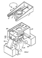
- the X-ray apparatus includes a stationary frame, which is 5 indicated in the drawing by reference numeral 1 and which, in addition to the part shown in the drawing, normally includes a vertical pole attached to it and a stand resting on the floor.
- the protruding part 1 shown in the drawing is, of course, in practice encased, but for the sake of illustration this casing is not shown.
- a bearing part 2 which is capable of moving in the frame linearly along a horizontal plane and supported by rails 3.
- the movement is produced by a stepping motor 4, the shaft of which is a screw 5 which works in conjunction with the bearing part 2.
- a sleeve 6 which is rotated by another stepping motor 7 by transmission of a cogged belt 8.
- a casing-like part 9 which thus rotates together with the sleeve 6 and to which there is further attached with bearings in a manner depicted below a support arm 10, which constitutes an essential part of the photography apparatus.
- a movable X-ray film 11 At one end of the support arm there is a movable X-ray film 11 and at its opposite end a source 12 of X-radiation with means for limiting the beam.
- the support arm 10 performs at least a partial rotational movement, the fulcrum moving at the same time linearly together with the bearing part 2, and the head of the patient being located between the source 12 of X-radiation and the X-ray film 11.
- curved guides 13, which work in conjunction with corresponding curved guides 14 in the control part 16.
- a strip 24 At the lower edge of the side piece 23 of the control part 16 there is additionally a strip 24, and the flat middle section 22 of the support arm 10 can move supported by this strip.
- the last-mentioned movement in a direction parallel to the X-ray beam is produced by a stepping motor 19, which rotates a transverse shaft and its cogwheels 20, the cogwheels for their part working in conjunction with cogged bars 21 in the middle section 22.
- stepping motor 19 which rotates a transverse shaft and its cogwheels 20, the cogwheels for their part working in conjunction with cogged bars 21 in the middle section 22.
- friction wheels Respectively, of course, it is possible to use friction wheels.
- the control part 16 for its part is moved by a screw 18 which grips it in an articulated way and serves as the shaft of the stepping motor 17, which for its part is articulated by means of a transverse shaft 15 to the casing part 9.
- the motor 17 thus affects the mutual shifting of the guides 13 and 14, and since the guides are curved, the transfer motor 17 of the control part 16 has been suspended in an articulated way.
- the image enlargement coefficient can be changed by moving the support arm 10 in a direction parallel to the beam, in other words by means of the motor 19.
- By rotating the support arm 10 180 it is thus possible to allow the source of radiation to travel around either the neck or the face of the patient, and a suitable enlargement coefficient can be produced without shifting the patient.
- the support arm when somewhat slanted teeth are being photographed, it may be appropriate to tilt the support arm by means of the motor 17 and the curved rails 13, 14, at which time it is, of course,-advisable also to limit the X-ray beam in the vertical direction in such a way that the teeth of only the upper jaw or the lower jaw are photographed.
- the tilting does not substantially alter the distance of the source of radiation, respectively the film, from the patient, which would occur if the tilting were produced by means of a horizontal transverse shaft.
- the linear transfer i.e. the transfer in a direction parallel to the plane of the X-ray beam, is produced by means of a plate 26 attached to the sleeve 6, the edges of the plate being guided by rails 28 on the sides of the casing-like part 27.
- the transfer is effected by means of a motor 29, which is secured to the lower surface of the plate 26.
- At least the middle section of the support arm 10 is curved in such a way that the center point of the curve, i.e. the tilting axis, is again located approximately at the level of the head of the patient 25.
- Rollers 30, 31, attached by means of bearings inside the casing 27, work in conjunction with the arch 10, the rollers working against the side, upper and lower surfaces of the arch (the last-mentioned not shown), directing the arch along its own curved line.
- the transfer movement is produced by means of a spindle motor 32 attached turnably to the casing 27 by means of a shaft 33, the threaded shaft 34 of the motor engaging in a mating piece 35 attached turnably to the side of the arch.
- the film must also be moved synchronically with the rotational movement of the support arm.
- the shifting of the film is also produced preferably by means of a stepping motor, although this arrangement is not shown in the drawing.
- stepping motors are preferably controlled electronically in a manner known per se, especially by means of a programmed or a programmable microprocessor, in which case no mechanical means such as cams or the like are required for mutual synchronization of the movements of the different parts.
Landscapes
- Health & Medical Sciences (AREA)
- Life Sciences & Earth Sciences (AREA)
- Medical Informatics (AREA)
- Engineering & Computer Science (AREA)
- Optics & Photonics (AREA)
- Biomedical Technology (AREA)
- Biophysics (AREA)
- High Energy & Nuclear Physics (AREA)
- Oral & Maxillofacial Surgery (AREA)
- Nuclear Medicine, Radiotherapy & Molecular Imaging (AREA)
- Dentistry (AREA)
- Pathology (AREA)
- Radiology & Medical Imaging (AREA)
- Physics & Mathematics (AREA)
- Heart & Thoracic Surgery (AREA)
- Molecular Biology (AREA)
- Surgery (AREA)
- Animal Behavior & Ethology (AREA)
- General Health & Medical Sciences (AREA)
- Public Health (AREA)
- Veterinary Medicine (AREA)
- Apparatus For Radiation Diagnosis (AREA)
Applications Claiming Priority (2)
| Application Number | Priority Date | Filing Date | Title |
|---|---|---|---|
| FI840412 | 1984-02-01 | ||
| FI840412A FI88671C (fi) | 1984-02-01 | 1984-02-01 | Roentgenfotograferingsanordning foer taenderna och hakorna |
Publications (3)
| Publication Number | Publication Date |
|---|---|
| EP0155072A2 true EP0155072A2 (de) | 1985-09-18 |
| EP0155072A3 EP0155072A3 (en) | 1987-05-20 |
| EP0155072B1 EP0155072B1 (de) | 1990-11-14 |
Family
ID=8518469
Family Applications (1)
| Application Number | Title | Priority Date | Filing Date |
|---|---|---|---|
| EP85300524A Expired - Lifetime EP0155072B1 (de) | 1984-02-01 | 1985-01-25 | Gerät zur Röntgenphotographie des Zahnbogens und der Kiefer |
Country Status (9)
| Country | Link |
|---|---|
| US (1) | US4683581A (de) |
| EP (1) | EP0155072B1 (de) |
| JP (1) | JPS60179045A (de) |
| AU (1) | AU570766B2 (de) |
| CA (1) | CA1252328A (de) |
| DE (1) | DE3580500D1 (de) |
| ES (1) | ES539981A0 (de) |
| FI (1) | FI88671C (de) |
| SU (1) | SU1424721A3 (de) |
Cited By (2)
| Publication number | Priority date | Publication date | Assignee | Title |
|---|---|---|---|---|
| GB2186770A (en) * | 1986-02-04 | 1987-08-19 | Orion Yhtymae Oy | Radiography of dental, jaw and skull regions |
| EP3586751B1 (de) | 2017-02-23 | 2021-07-07 | J. Morita Manufacturing Corporation | Röntgentomograf und röntgentomografieverfahren |
Families Citing this family (12)
| Publication number | Priority date | Publication date | Assignee | Title |
|---|---|---|---|---|
| JPS6122842A (ja) * | 1984-07-10 | 1986-01-31 | 朝日レントゲン工業株式会社 | 歯科用全顎x線撮影装置 |
| CH666803A5 (de) * | 1985-01-25 | 1988-08-31 | Hanspeter Dr Med Dent Delnon | Geraet zur aufnahme von roentgen-schichtbildern. |
| DE3679652D1 (de) * | 1985-12-20 | 1991-07-11 | Siemens Ag | Zahnaerztliches roentgendiagnostikgeraet zur erstellung von panorama-schichtaufnahmen vom kiefer eines patienten. |
| FI73326B (fi) * | 1986-01-23 | 1987-05-29 | Radiante Oy | Foerfarande och anordning foer upptagning och aotergivning av bildinformation vid roentgenpanoramaavbildning. |
| FI98488C (fi) * | 1993-01-08 | 1997-07-10 | Orion Yhtymae Oy | Menetelmä vakiosuurennuksen toteuttamiseksi panoraamaröntgenkuvauksessa |
| FI104943B (fi) * | 1998-06-26 | 2000-05-15 | Planmeca Oy | Menetelmä, laite ja niiden käyttö tomografiakuvantamisessa 2 |
| WO2002017790A1 (en) * | 2000-08-29 | 2002-03-07 | Vladimir Ivanovich Popov | Radiographic scanning device |
| FI110822B (fi) * | 2001-03-27 | 2003-03-31 | Planmeca Oy | Menetelmä ja järjestely röntgenlaitteiden, erityisesti panoraamaröntgenkuvauslaitteiden toimilaitteiden liikkeiden toteuttamiseksi |
| CA2454634A1 (en) | 2001-07-25 | 2003-02-06 | Giuseppe Rotondo | Real-time digital x-ray imaging apparatus |
| WO2004014232A1 (en) | 2002-07-25 | 2004-02-19 | Gendex Corporation | Real-time digital x-ray imaging apparatus and method |
| JP2004136027A (ja) * | 2002-10-21 | 2004-05-13 | Univ Nihon | 画像処理装置 |
| JP5206822B2 (ja) | 2010-07-09 | 2013-06-12 | 株式会社デンソー | 半導体装置 |
Family Cites Families (11)
| Publication number | Priority date | Publication date | Assignee | Title |
|---|---|---|---|---|
| US2595260A (en) * | 1949-02-05 | 1952-05-06 | F R Machine Works | Multiplane X-ray apparatus |
| FR2054492B1 (de) * | 1969-07-16 | 1974-06-14 | Radiologie Cie Gle | |
| DE2134122C3 (de) * | 1971-07-08 | 1984-05-30 | Siemens AG, 1000 Berlin und 8000 München | Röntgengerät für Schädeluntersuchungen |
| JPS52103988A (en) * | 1976-02-25 | 1977-08-31 | Morita Mfg | Method and device for taking curved sectional plane of xxray |
| FI66993C (fi) * | 1976-12-10 | 1984-12-10 | Orion Yhtymae Oy | Roerelsemekanism foer en roentgenstraolningskaellan och filmhaollare foer panorama-roentgenfotografering |
| DE2758191A1 (de) * | 1977-12-27 | 1979-06-28 | Siemens Ag | Zahnaerztliche roentgendiagnostikeinrichtung |
| JPS551053A (en) * | 1978-06-19 | 1980-01-07 | Daido Steel Co Ltd | Electrode gripper for arc furnace |
| DE3007935A1 (de) * | 1980-03-01 | 1981-09-17 | Philips Patentverwaltung Gmbh, 2000 Hamburg | Dental-tomographiegeraet |
| US4373361A (en) * | 1981-04-13 | 1983-02-15 | Thorneburg James L | Ski sock with integrally knit thickened fabric areas |
| DE3276255D1 (en) * | 1981-06-23 | 1987-06-11 | Thomson Csf | Sliding load holder with a telescopic structure and x-ray apparatus provided with such a sliding load holder |
| US4534048A (en) * | 1983-01-03 | 1985-08-06 | Pennwalt Corporation | Methods of increasing anterior layer thickness of continuous dental images obtained through rotational panoramic radiography |
-
1984
- 1984-02-01 FI FI840412A patent/FI88671C/fi not_active IP Right Cessation
-
1985
- 1985-01-23 AU AU38000/85A patent/AU570766B2/en not_active Ceased
- 1985-01-25 DE DE8585300524T patent/DE3580500D1/de not_active Expired - Lifetime
- 1985-01-25 EP EP85300524A patent/EP0155072B1/de not_active Expired - Lifetime
- 1985-01-30 ES ES539981A patent/ES539981A0/es active Granted
- 1985-01-31 SU SU853857497A patent/SU1424721A3/ru active
- 1985-01-31 US US06/696,776 patent/US4683581A/en not_active Expired - Lifetime
- 1985-01-31 CA CA000473329A patent/CA1252328A/en not_active Expired
- 1985-01-31 JP JP60017688A patent/JPS60179045A/ja active Granted
Cited By (4)
| Publication number | Priority date | Publication date | Assignee | Title |
|---|---|---|---|---|
| GB2186770A (en) * | 1986-02-04 | 1987-08-19 | Orion Yhtymae Oy | Radiography of dental, jaw and skull regions |
| AU598513B2 (en) * | 1986-02-04 | 1990-06-28 | Orion-Yhtyma Oy | Method and apparatus for radiography of the dental, jaw, and skull regions |
| GB2186770B (en) * | 1986-02-04 | 1990-07-11 | Orion Yhtymae Oy | Method and apparatus for radiography of the dental, jaw and skull regions |
| EP3586751B1 (de) | 2017-02-23 | 2021-07-07 | J. Morita Manufacturing Corporation | Röntgentomograf und röntgentomografieverfahren |
Also Published As
| Publication number | Publication date |
|---|---|
| ES8601672A1 (es) | 1985-11-16 |
| EP0155072B1 (de) | 1990-11-14 |
| DE3580500D1 (de) | 1990-12-20 |
| SU1424721A3 (ru) | 1988-09-15 |
| FI88671C (fi) | 1993-06-28 |
| FI840412A0 (fi) | 1984-02-01 |
| AU3800085A (en) | 1985-08-08 |
| JPH0554341B2 (de) | 1993-08-12 |
| CA1252328A (en) | 1989-04-11 |
| AU570766B2 (en) | 1988-03-24 |
| EP0155072A3 (en) | 1987-05-20 |
| ES539981A0 (es) | 1985-11-16 |
| FI840412A7 (fi) | 1985-08-02 |
| FI88671B (fi) | 1993-03-15 |
| JPS60179045A (ja) | 1985-09-12 |
| US4683581A (en) | 1987-07-28 |
Similar Documents
| Publication | Publication Date | Title |
|---|---|---|
| US4683581A (en) | Apparatus for X-ray photography of the area of the dentition and of the jaws | |
| US5023899A (en) | Method and arrangement for X-ray photography or the like | |
| JPH0715524Y2 (ja) | 歯科用パノラマ・セファロx線撮影装置 | |
| JPH11509461A (ja) | 患者支持体 | |
| US3908126A (en) | X-ray apparatus for providing panoramic radiographic projections | |
| US5506879A (en) | Planigraphic X-ray apparatus | |
| EP0151007B1 (de) | Gerät zur Röntgen-Photographie des Zahnbogens und der Kiefer | |
| KR20220016205A (ko) | Ct 이미징 장치 | |
| US4484343A (en) | Tilting table X-ray apparatus | |
| US3778049A (en) | Angiographic cradle | |
| EP3975854B1 (de) | Ct-bildgebungsvorrichtung | |
| US2789231A (en) | Appliance for radiographic representation of sections of the body | |
| CA1042563A (en) | Dental x-ray machine | |
| WO2000000087A1 (en) | Method, apparatus and their use in tomographic imaging | |
| US5386449A (en) | Method and a device for carrying out constant enlargement in panoramic tomographic X-ray photography | |
| JPH01209047A (ja) | 乳房撮影装置 | |
| US4321472A (en) | Panoramic dental X-ray machine with camera detached therefrom | |
| US5148454A (en) | Apparatus for conducting cranial X-ray tomography and radiography | |
| JPS5839687Y2 (ja) | 断層x線撮影装置 | |
| JPS5839693Y2 (ja) | パノラマx線撮影装置の運動機構 | |
| JPS61276544A (ja) | 断層撮影装置 | |
| JPS60108037A (ja) | コンピュ−タ断層撮影装置 | |
| JPH04288152A (ja) | X線断層撮影装置 |
Legal Events
| Date | Code | Title | Description |
|---|---|---|---|
| PUAI | Public reference made under article 153(3) epc to a published international application that has entered the european phase |
Free format text: ORIGINAL CODE: 0009012 |
|
| AK | Designated contracting states |
Designated state(s): AT BE CH DE FR GB IT LI NL SE |
|
| PUAL | Search report despatched |
Free format text: ORIGINAL CODE: 0009013 |
|
| AK | Designated contracting states |
Kind code of ref document: A3 Designated state(s): AT BE CH DE FR GB IT LI NL SE |
|
| 17P | Request for examination filed |
Effective date: 19870908 |
|
| 17Q | First examination report despatched |
Effective date: 19890615 |
|
| RBV | Designated contracting states (corrected) |
Designated state(s): DE FR GB IT NL |
|
| ITF | It: translation for a ep patent filed | ||
| GRAA | (expected) grant |
Free format text: ORIGINAL CODE: 0009210 |
|
| AK | Designated contracting states |
Kind code of ref document: B1 Designated state(s): DE FR GB IT NL |
|
| ET | Fr: translation filed | ||
| REF | Corresponds to: |
Ref document number: 3580500 Country of ref document: DE Date of ref document: 19901220 |
|
| PLBI | Opposition filed |
Free format text: ORIGINAL CODE: 0009260 |
|
| 26 | Opposition filed |
Opponent name: INSTRUMENTARIUM CORP. IMAGING Effective date: 19910808 |
|
| NLR1 | Nl: opposition has been filed with the epo |
Opponent name: INSTRUMENTARIUM CORP. IMAGING |
|
| ITTA | It: last paid annual fee | ||
| PLBN | Opposition rejected |
Free format text: ORIGINAL CODE: 0009273 |
|
| STAA | Information on the status of an ep patent application or granted ep patent |
Free format text: STATUS: OPPOSITION REJECTED |
|
| 27O | Opposition rejected |
Effective date: 19940214 |
|
| NLR2 | Nl: decision of opposition | ||
| PGFP | Annual fee paid to national office [announced via postgrant information from national office to epo] |
Ref country code: FR Payment date: 20001229 Year of fee payment: 17 |
|
| PGFP | Annual fee paid to national office [announced via postgrant information from national office to epo] |
Ref country code: GB Payment date: 20010102 Year of fee payment: 17 |
|
| PGFP | Annual fee paid to national office [announced via postgrant information from national office to epo] |
Ref country code: NL Payment date: 20010119 Year of fee payment: 17 |
|
| REG | Reference to a national code |
Ref country code: GB Ref legal event code: IF02 |
|
| PG25 | Lapsed in a contracting state [announced via postgrant information from national office to epo] |
Ref country code: GB Free format text: LAPSE BECAUSE OF NON-PAYMENT OF DUE FEES Effective date: 20020125 |
|
| PG25 | Lapsed in a contracting state [announced via postgrant information from national office to epo] |
Ref country code: NL Free format text: LAPSE BECAUSE OF NON-PAYMENT OF DUE FEES Effective date: 20020801 |
|
| GBPC | Gb: european patent ceased through non-payment of renewal fee |
Effective date: 20020125 |
|
| PG25 | Lapsed in a contracting state [announced via postgrant information from national office to epo] |
Ref country code: FR Free format text: LAPSE BECAUSE OF NON-PAYMENT OF DUE FEES Effective date: 20020930 |
|
| NLV4 | Nl: lapsed or anulled due to non-payment of the annual fee |
Effective date: 20020801 |
|
| REG | Reference to a national code |
Ref country code: FR Ref legal event code: ST |
|
| PGFP | Annual fee paid to national office [announced via postgrant information from national office to epo] |
Ref country code: DE Payment date: 20040126 Year of fee payment: 20 |
|
| PLAB | Opposition data, opponent's data or that of the opponent's representative modified |
Free format text: ORIGINAL CODE: 0009299OPPO |