EP0154783B1 - Dispositif pour tourner de la vaisselle à forme non-sphérique - Google Patents
Dispositif pour tourner de la vaisselle à forme non-sphérique Download PDFInfo
- Publication number
- EP0154783B1 EP0154783B1 EP85100827A EP85100827A EP0154783B1 EP 0154783 B1 EP0154783 B1 EP 0154783B1 EP 85100827 A EP85100827 A EP 85100827A EP 85100827 A EP85100827 A EP 85100827A EP 0154783 B1 EP0154783 B1 EP 0154783B1
- Authority
- EP
- European Patent Office
- Prior art keywords
- workpiece
- axis
- shaping head
- workpiece support
- pin
- Prior art date
- Legal status (The legal status is an assumption and is not a legal conclusion. Google has not performed a legal analysis and makes no representation as to the accuracy of the status listed.)
- Expired
Links
Images


Classifications
-
- B—PERFORMING OPERATIONS; TRANSPORTING
- B23—MACHINE TOOLS; METAL-WORKING NOT OTHERWISE PROVIDED FOR
- B23Q—DETAILS, COMPONENTS, OR ACCESSORIES FOR MACHINE TOOLS, e.g. ARRANGEMENTS FOR COPYING OR CONTROLLING; MACHINE TOOLS IN GENERAL CHARACTERISED BY THE CONSTRUCTION OF PARTICULAR DETAILS OR COMPONENTS; COMBINATIONS OR ASSOCIATIONS OF METAL-WORKING MACHINES, NOT DIRECTED TO A PARTICULAR RESULT
- B23Q27/00—Geometrical mechanisms for the production of work of particular shapes, not fully provided for in another subclass
-
- B—PERFORMING OPERATIONS; TRANSPORTING
- B28—WORKING CEMENT, CLAY, OR STONE
- B28B—SHAPING CLAY OR OTHER CERAMIC COMPOSITIONS; SHAPING SLAG; SHAPING MIXTURES CONTAINING CEMENTITIOUS MATERIAL, e.g. PLASTER
- B28B1/00—Producing shaped prefabricated articles from the material
- B28B1/02—Producing shaped prefabricated articles from the material by turning or jiggering in moulds or moulding surfaces on rotatable supports
Definitions
- a known machine of this type (EP-A 0 018 171), which is designed for rotating oval bowls, has two workpiece carriers, each of which can be driven by a vertical shaft via an eccentric drive such that they each rotate about their own vertical axis while it is performing a planetary movement around the geometric axis of the associated shaft.
- Each of the workpiece carriers is assigned a shaping head which is rotatably mounted about its own axis on a cantilever which can be tilted about a horizontal axis on a base part of a tool stand.
- One of the two eccentrically drivable workpiece carriers together with the associated shaping head is provided for preforming, the other workpiece carrier together with the associated shaping head is provided for the final shaping of the oval bowls.
- each shaping head By tilting each shaping head in relation to the associated workpiece carrier, as is also the case when turning round dishes, the ceramic mass of a batch of material or preformed workpiece placed on the workpiece carrier is to be gradually pushed outwards, so that a ring-shaped area is formed after a substantially flat central region Foot and an outer edge area of the resulting dishes are formed.
- an annular groove is formed on the shaping head.
- Oval dishes that have been turned on the known machine have a tendency to warp and / or tear on their feet when burning. This tendency is greater, the more the outline of the crockery parts deviates from a circular shape and the higher the foot.
- the invention is based on the knowledge that these undesirable tendencies are due to unevenness in the mass structure which arises during turning.
- the known two-stage shape of the crockery parts can alleviate their tendency to warp and / or tear, but not completely eliminate them; it is also time consuming to process the workpieces one after the other with two different shaping heads.
- the invention is therefore based on the object of developing a machine of the type described at the outset in such a way that oval or other non-round, for example rounded square, rectangular or hexagonal crockery parts can be rotated with little expenditure of time and such crockery parts are perfect to at least approximately the same extent as in the usual way round dishes.
- the tool stand can be moved in an oscillating manner in a plane that is at least approximately normal to the axis of the workpiece carrier and can be driven in such a way that it is coordinated with the essentially radially reciprocating relative movement such that the axis of the shaping head is in the region of its action the workpiece crosses this tangent at least approximately at right angles.
- the tool stand is attached to a coupling member which is articulated on the one hand with a crank pin of the gear arrangement mentioned and on the other hand with an axle pin, these two pins being at least approximately parallel to the axis of the workpiece carrier.
- crank pin and axle pin are adjustable at right angles to their axial direction.
- crank pin and axle pin are each attached to a control disk by means of a diametrically adjustable slide and are connected to one another by the gear arrangement mentioned in a gear ratio of 1: 1.
- crank pin For rotating oval crockery parts, the embodiment of the invention described above with crank pin is designed in such a way that the gear arrangement between the workpiece carrier and the crank pin has a transmission ratio of 1: 2. This means that with every rotation of the workpiece carrier, the crank pin performs two rotations.
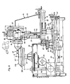
- the machine shown in FIGS. 1 to 5 is intended to rotate on a porous shape SM with its upside down oval dish-shaped tableware parts FF made of ceramic mass.
- the machine has a machine frame 10 on which a workpiece carrier 11 receiving the porous shape SM as well as a rear and a front control disk 12 and 13 are rotatably mounted at a distance from each other about a vertical axis.
- the axes of rotation of the workpiece carrier 11 and the two control disks 12 and 13 lie in a common vertical plane.
- the two control disks 12 and 13 are connected to one another by a coupling member 14, which is movable in a horizontal plane and carries a tool stand 15.
- the tool stand 15 consists essentially of a base part 16, which is fastened to the coupling member 14, and an extension arm 18, which can be tilted with respect to a common vertical central plane of the base part 16 and the extension arm 18.
- a tool spindle 19 is tiltably mounted in the plane mentioned; a shaping head 20 is mounted on it.
- a first pneumatic piston-cylinder unit 21 is provided for tilting the boom 18 with respect to the base part 16; a second pneumatic piston-cylinder unit 22 serves to tilt the tool spindle 19 in relation to the boom 18.
- the workpiece holder 11 is connected to the tool stand 15 by a gear arrangement 23.
- a drive motor (not shown) for the gear arrangement 23 is coupled to the tool spindle 19 below.
- the two control disks 12 and 13 are each attached to the upper end of a control shaft 26 or 27, which is mounted in a bearing 28 or 29 on the machine frame 10 and is fixedly connected to a pinion 30 or 31 at its lower end.
- the two pinions 30 and 31 have the same number of teeth, which are half the number of teeth of the gear 25.
- a chain 32 loops around the gear 25, the two pinions 30 and 31 and a plurality of freely rotatable chain wheels 33, by which it is deflected and held under tension .
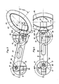
- the arm 18 of the tool stand 15 is composed of two parallel vertical plates 33A and 33B, which are connected to one another by a rear transverse bolt 34 and two front transverse bolts 35.
- a further connection of the two plates 33A and 33B to one another is formed by a tilting bearing 36 which connects the arm 18 to the base part 16 and extends horizontally at right angles to the coupling member 14.
- the two plates 33A and 33B each have an essentially vertical elongated hole 37 at the front.
- the elongated holes 37 lie opposite one another and each take a bearing block 38 on which the height can be adjusted and clamped.
- a horizontal shaft 39 is mounted in the two bearing blocks 38, at one end 40 of which an end 41 of a crank 42 is fastened.
- the piston rod 44 of the double-acting pneumatic piston-cylinder unit 22 is connected to the other end 43 of the crank 42.
- the cylinder of this unit 22 is supported on the plate 33A of the boom 18.
- the other piston-cylinder unit 21 connects a cross pin 45 at the rear upper end 46 of the base part 16 to the rear cross pin 34 between the two plates 33A and 33B of the boom 18.
- the two piston-cylinder units 21 and 22 are not one shown joint control actuated timed to each other.
- a slide 50 is guided in a diametrically adjustable manner and can be locked with a clamping device 51.
- a vertical journal 52 is fastened on the slide 50.
- a carriage 55 is guided in a diametrically adjustable manner on the front control disk 13 and can be locked with a clamping device 56; a vertical crank pin 57 is fastened on the slide 55.
- the two pins 52 and 57 can be adjusted eccentrically with respect to the associated shaft 26 and 27, independently of one another.
- the risk of jamming due to inaccuracies in the manufacture or setting of parts of the gear arrangement 23 is avoided in that the axle journal 52 is guided in an elongated hole 60 on the rear part 61 of the coupling member 14.
- the coupling member 14 is mounted with its front end 62A on the front pin 57 without play by means of a bush 62.
- the coupling member 14 has a further elongated hole in its central region 63, in which a vertical rod 64 engages.
- the rod 64 is fixed in an elongated hole in the machine frame 10; the center line of this elongated hole lies in the same vertical plane as the geometric axes of the workpiece spindle 24 and the two shafts 26 and 27.
- the base part 16 of the tool stand 15 has elongated holes 65 near its lower edge, which extend in the longitudinal direction of the coupling member 14 and each receive a releasable fastening screw 66.
- the drive motor of the machine is started, which rotates the gear 25 and from there via the gear arrangement 23 also the pinions 30 and 31, whereby the tool carrier 11 and the control disks 12 and 13 are rotated; Because of the diameter or number of teeth ratios described, the control disks 12 and 13 rotate at twice the speed of the workpiece carrier 11.
- the shaping head 20 is lowered onto the workpiece FF by first extending the pneumatic unit 21, as a result of which the boom 18 is tilted clockwise around the tilting bearing 36 in relation to FIG. 1. Then, by extending the pneumatic unit 22, the shaft 39 is also rotated clockwise, as a result of which the tool spindle 19 together with the shaping head 20 is tilted accordingly.
- the shaping head 20 initially hits the workpiece FF at an angle, as indicated by broken lines; then, after a certain number of revolutions of the workpiece carrier 11, the shaping head 20 assumes the horizontal position drawn with full lines in FIG. 1.
- the shaping head 20 which can be freely rotated in the exemplary embodiment according to FIGS. 1 to 5 is also rotated by the rotation of the workpiece carrier 11. In its horizontal position, the shaping head 20 models the lower part of the workpiece FF with the rib BP, which is shaped as the foot of the tableware part by an annular groove 20A in the shaping head 20.
- the groove 20A separates a cylindrical part 20B of the shaping head 20 which forms the flat central region PC of the workpiece FF from a frustoconical apron 20C which forms the outer part PE of the workpiece FF.
- the two-stage lowering of the shaping head 20 causes the imageable material of the originally sheet-shaped workpiece FF to flow outwards and downwards, thereby favoring the shaping.
- FIGS. 3 and 4 Two positions of the workpiece FF with respect to the forming head 20 are shown in FIGS. 3 and 4.
- the composite rotational and translational movement of the coupling member 14 results, as clearly shown, from the phase-shifted rotational movement of the control discs 12 and 13 and the arrangement of the elongated hole 60 and causes the axis of rotation B of the shaping head 20 to be normal, that is to say at right angles to Tangent T extends to the geometric curve which is determined by the edge BP at all of its points.
- This has proven to be an indispensable prerequisite for a precise shaping of the lower part of the workpiece FF to be produced.
- the apron 20C of the shaping head 20 squeezes either the outer part PE or the base edge BP of the plate to be produced.
- Crockery parts other than the shapes and dimensions shown in the accompanying drawings can also be produced on the machine according to the invention. To make this possible, it is sufficient to change the positions of the carriages 50 and 55, the relative position of the workpiece spindle 24 with respect to the shafts 26 and 27 of the control disks 12 and 13 and the transmission ratio of the gear arrangement 23.
- Another possibility of changing the parameters of the action on the workpiece FF is finally to adjust the base part 16 of the tool stand 15 in relation on the coupling member 14. Such an adjustment results in a corresponding displacement of the shaping head 20 with respect to the workpiece holder 11.
- the machine according to the invention can also be used with a correspondingly modified molded part SM and shaping head 20 for rotating the top of tableware parts.
- axle journal 52 and crank journal 57 are interchangeable, since each of these two journals responsible for the combined pivoting and displacements of the coupling member 14 can be adjusted eccentrically.
- axle journal 52 is fastened on a slide 53 which can be adjusted by means of a manually operated threaded spindle 54 along a common normal of the axle journal 52, the shaft 27 and the workpiece spindle 24.
- the carriage 53 is guided on a further carriage 58 which can be adjusted in the same direction as the carriage 53 by means of a threaded spindle 59 and which supports the bearing 29 of the control shaft 27.
- the two threaded spindles 54 and 59 have equal pitches and are connected to one another by a chain drive 67 in such a way that the threaded spindle 59 only makes half a revolution with each full rotation of the threaded spindle 54; with each adjustment of the journal 52 in one direction or the other, the control shaft 27 is adjusted in the same direction, but only half as far.
- the machine according to FIG. 6 differs from that shown in FIGS. 1 to 5 further in that a horizontal bush 68 is mounted on the vertical journal 52, in which a cylindrical rod 69 belonging to the coupling member 14 and arranged in the longitudinal direction thereof is displaceably guided is.
- the base part 16 of the tool stand 15 can be adjusted in the longitudinal direction of the coupling 14 by means of a manually operated threaded spindle 70.
- a vertical guide 71 is formed on the base part 16, which guides the boom 18, which in this case is designed like a sled. Accordingly, the piston-cylinder unit 21 is provided to move the boom 18 vertically.
- a stop screw 72 is provided as a limitation for the downward movement of the boom 18.
- a further deviation of the machine according to FIG. 6 from that shown in FIGS. 1 to 5 is that the workpiece spindle 24 is not directly coupled to a motor, but rather a motor 73 shown in FIG. 6 via a continuously variable transmission 74 a vertical one Drives shaft 75, which is connected to the workpiece spindle 24 by a chain drive 76 with a tooth ratio of 1: 2 and is further connected to the control shaft 27 via a bevel gear 77, a telescopic shaft 78 and a further bevel gear 79 in a 1: 1 ratio.
- the transmission ratio of the entire gear arrangement 23 is again such that the control disk 13 together with the crank pin 57 performs two full rotations with each full rotation of the workpiece carrier 11.
- the machine according to FIG. 6 differs from that shown in FIGS. 1 to 5 in that the shaping head 20 can be driven by its own motor 80 via a continuously variable transmission 81.
- FIG. 7 The machine according to FIG. 7 is largely the same as that shown in FIG. 6, but differs from it in the following features:
- the coupling member 14 is fixedly mounted on the vertical journal 52, the bearing 29 of which, however, is arranged on a carriage 58 as in FIG. 6.
- a roller 82 is mounted on the crank pin 55 and is guided in a longitudinal groove 83 of the coupling member 14.
- an arc-shaped guide 84 is fastened coaxially with the bearing 29, on which the coupling member 14 is supported with a roller 85 mounted on it.
- the machine according to FIG. 7 also differs from that shown in FIG. 6 in that the chain drive 76 does not directly drive the workpiece spindle 24, but rather a bush 86 which is mounted on a vertical pin 87 fastened to the machine frame 10 and one in relation on the pin 87 carries radial guide 88 on which an intermediate housing 89 is adjustably guided.
- a pinion 90 is fastened, which is connected to a gear 91 mounted on the intermediate housing 89 by double the diameter by a chain 92, which is additionally guided around a chain tensioning wheel 93 also mounted in the intermediate housing 89.
- the gear 91 is connected by a further chain gear 94 to the workpiece spindle 24, which rotates eccentrically with respect to the vertical pin 87 as it rotates about its own axis A.
- the workpiece carrier 11 therefore carries out a planetary movement in addition to the rotation about its own axis A, which is indicated in FIG. 8 by a circle.
- the shaping head 20 does not itself have to carry out the necessary translatory relative movements in a plane normal to the axis A of the workpiece carrier 11; accordingly, the base part 16 of the tool stand 15 can only be pivoted back and forth about the journal 52.
Landscapes
- Engineering & Computer Science (AREA)
- Mechanical Engineering (AREA)
- Physics & Mathematics (AREA)
- Geometry (AREA)
- Manufacturing & Machinery (AREA)
- Chemical & Material Sciences (AREA)
- Ceramic Engineering (AREA)
- Finish Polishing, Edge Sharpening, And Grinding By Specific Grinding Devices (AREA)
- Transmission Devices (AREA)
- Feeding Of Workpieces (AREA)
Claims (5)
caractérisée en ce que le porte-outil (15) peut être entraîné pour exécuter un mouvement pendulaire dans un plan au moins approximativement perpendiculaire à l'axe (A) du support de pièce (11) et qui est synchronisé avec le mouvement relatif de va et vient sensiblement radial de telle sorte que l'axe (B) de la tête de profilage (20) coupe au moins approximativement à angle droit une tangente (T) à la pièce (FF) dans la zone de son action sur la pièce.
caractérisée en ce que le porte-outil (15) est fixé sur un organe d'accouplement (14) qui est relié de façon articulée d'un côté avec un tourillon de manivelle (57) du mécanisme de transmission (23) précité et de l'autre côté avec un tourillon axial (53) et ces deux tourillons (57, 52) sont au moins approximativement parallèles à l'axe (A) du support de pièce (11).
caractérisée en ce que le tourillon de manivelle (57) et le tourillon axial (52) sont réglables à angle droit par rapport à leur direction axiale.
caractérisée en ce que le tourillon de manivelle (57) et le tourillon axial (52) sont chacun fixes au moyen d'un chariot (55, 50) déplaçable diamétralement sur un disque de commande respectif (13, 12) qui sont reliés entre eux, par l'intermédiaire du mécanisme de transmission (23) précité, avec un rapport de transmission de 1: 1.
Applications Claiming Priority (2)
| Application Number | Priority Date | Filing Date | Title |
|---|---|---|---|
| IT4760084 | 1984-01-26 | ||
| IT47600/84A IT1178103B (it) | 1984-01-26 | 1984-01-26 | Macchina per formare la parte infferiore degli articoli di stoviglieria allungati quali per esempio i piatti ovali |
Publications (2)
| Publication Number | Publication Date |
|---|---|
| EP0154783A1 EP0154783A1 (fr) | 1985-09-18 |
| EP0154783B1 true EP0154783B1 (fr) | 1987-04-08 |
Family
ID=11261353
Family Applications (1)
| Application Number | Title | Priority Date | Filing Date |
|---|---|---|---|
| EP85100827A Expired EP0154783B1 (fr) | 1984-01-26 | 1985-01-28 | Dispositif pour tourner de la vaisselle à forme non-sphérique |
Country Status (3)
| Country | Link |
|---|---|
| EP (1) | EP0154783B1 (fr) |
| DE (1) | DE3560114D1 (fr) |
| IT (1) | IT1178103B (fr) |
Families Citing this family (1)
| Publication number | Priority date | Publication date | Assignee | Title |
|---|---|---|---|---|
| WO2004026549A1 (fr) * | 2002-09-19 | 2004-04-01 | Hyun-Gwon Jo | Dispositif et procede de fabrication d'un produit presentant une forme ovale |
Family Cites Families (3)
| Publication number | Priority date | Publication date | Assignee | Title |
|---|---|---|---|---|
| DE1031084B (fr) * | 1955-03-24 | |||
| JPS4954981A (fr) * | 1972-09-29 | 1974-05-28 | ||
| US4286938A (en) | 1979-04-12 | 1981-09-01 | Service (Engineers) Limited | Oval dish former |
-
1984
- 1984-01-26 IT IT47600/84A patent/IT1178103B/it active
-
1985
- 1985-01-28 DE DE8585100827T patent/DE3560114D1/de not_active Expired
- 1985-01-28 EP EP85100827A patent/EP0154783B1/fr not_active Expired
Also Published As
| Publication number | Publication date |
|---|---|
| DE3560114D1 (en) | 1987-05-14 |
| EP0154783A1 (fr) | 1985-09-18 |
| IT8447600A1 (it) | 1985-07-26 |
| IT8447600A0 (it) | 1984-01-26 |
| IT1178103B (it) | 1987-09-09 |
Similar Documents
| Publication | Publication Date | Title |
|---|---|---|
| DE2760355C2 (fr) | ||
| DE3590093C2 (de) | Bearbeitungsmaschine zum Fräsen, Drehen und/oder Bohren | |
| DE69000888T2 (de) | Verfahren und vorrichtung zum abschraegen von einspringenden ecken bei tafeln aus farbigem oder nicht farbigem flachglas. | |
| EP0163066B1 (fr) | Table rotative de soudage | |
| DE2724929C2 (de) | Vorrichtung zum Gießen oder Spritzen von Fahrzeugreifen | |
| DE1906611B2 (de) | Drückmaschine zur Herstellung von Kesselböden | |
| DE1151714B (de) | Einrichtung zum Schaben von grossen Zahnraedern auf einer Zahnrad-Waelzfraesmaschine | |
| DE3120465A1 (de) | Saegenschaerfmaschine | |
| EP0154783B1 (fr) | Dispositif pour tourner de la vaisselle à forme non-sphérique | |
| DE3403720C2 (fr) | ||
| DE69228809T2 (de) | Maschine zum schaerfen von saegeblaettern | |
| DE3936200C1 (fr) | ||
| DE3404128C1 (de) | Numerisch gesteuerte Maschine zum Bearbeiten des Randes eines Keramikgegenstandes | |
| DE9312016U1 (de) | Vorrichtung zum Mischen, Schütteln, Rühren und/oder Emulgieren von Flüssigkeiten | |
| CH676212A5 (fr) | ||
| DE3814241C1 (fr) | ||
| DE2452233A1 (de) | Konturenschleifmaschine | |
| DE3110624C2 (de) | Vorrichtung zum Herstellen einer Kontaktlinse | |
| DE1267943B (de) | Vorrichtung zum Fraesen und Schleifen von Walzkalibern | |
| AT250130B (de) | Verfahren, Werkzeug und Maschine zur materialabtragenden Bearbeitung von Werkstücken | |
| DE1552739A1 (de) | Verfahren und Vorrichtung zur Herstellung von Zahnraedern | |
| DE2152300A1 (de) | Tragleiste fuer Stabkoerper-Herstellungsmaschine,insbesondere fuer Zigaretten- und Filterherstellungsmaschinen | |
| AT89105B (de) | Maschine zum Fräsen von Kegelrädern nach dem Abwälzverfahren. | |
| DE517147C (de) | Ovalwerk, insbesondere zum Schleifen der Raender von ovalen Glasscheiben | |
| DE7139488U (de) | Drechslerei Fräsmaschine zur Stirn oder Querholzbearbeitung |
Legal Events
| Date | Code | Title | Description |
|---|---|---|---|
| PUAI | Public reference made under article 153(3) epc to a published international application that has entered the european phase |
Free format text: ORIGINAL CODE: 0009012 |
|
| 17P | Request for examination filed |
Effective date: 19850603 |
|
| AK | Designated contracting states |
Designated state(s): DE FR GB IT |
|
| 17Q | First examination report despatched |
Effective date: 19860804 |
|
| ITF | It: translation for a ep patent filed | ||
| GRAA | (expected) grant |
Free format text: ORIGINAL CODE: 0009210 |
|
| AK | Designated contracting states |
Kind code of ref document: B1 Designated state(s): DE FR GB IT |
|
| REF | Corresponds to: |
Ref document number: 3560114 Country of ref document: DE Date of ref document: 19870514 |
|
| ET | Fr: translation filed | ||
| PLBE | No opposition filed within time limit |
Free format text: ORIGINAL CODE: 0009261 |
|
| STAA | Information on the status of an ep patent application or granted ep patent |
Free format text: STATUS: NO OPPOSITION FILED WITHIN TIME LIMIT |
|
| 26N | No opposition filed | ||
| PG25 | Lapsed in a contracting state [announced via postgrant information from national office to epo] |
Ref country code: GB Effective date: 19890128 |
|
| ITTA | It: last paid annual fee | ||
| GBPC | Gb: european patent ceased through non-payment of renewal fee | ||
| PGFP | Annual fee paid to national office [announced via postgrant information from national office to epo] |
Ref country code: FR Payment date: 19891207 Year of fee payment: 6 |
|
| PGFP | Annual fee paid to national office [announced via postgrant information from national office to epo] |
Ref country code: DE Payment date: 19900129 Year of fee payment: 6 |
|
| PG25 | Lapsed in a contracting state [announced via postgrant information from national office to epo] |
Ref country code: FR Effective date: 19910930 |
|
| PG25 | Lapsed in a contracting state [announced via postgrant information from national office to epo] |
Ref country code: DE Effective date: 19911001 |
|
| REG | Reference to a national code |
Ref country code: FR Ref legal event code: ST |