EP0154571A1 - Machining centre for sequential machining - Google Patents
Machining centre for sequential machining Download PDFInfo
- Publication number
- EP0154571A1 EP0154571A1 EP85400131A EP85400131A EP0154571A1 EP 0154571 A1 EP0154571 A1 EP 0154571A1 EP 85400131 A EP85400131 A EP 85400131A EP 85400131 A EP85400131 A EP 85400131A EP 0154571 A1 EP0154571 A1 EP 0154571A1
- Authority
- EP
- European Patent Office
- Prior art keywords
- machining
- units
- machine according
- circuit
- housings
- Prior art date
- Legal status (The legal status is an assumption and is not a legal conclusion. Google has not performed a legal analysis and makes no representation as to the accuracy of the status listed.)
- Granted
Links
- 238000003754 machining Methods 0.000 title claims abstract description 81
- 125000004122 cyclic group Chemical group 0.000 claims abstract description 3
- 238000007664 blowing Methods 0.000 description 2
- 238000005406 washing Methods 0.000 description 2
- 238000005553 drilling Methods 0.000 description 1
- 238000003801 milling Methods 0.000 description 1
Images

Classifications
-
- B—PERFORMING OPERATIONS; TRANSPORTING
- B23—MACHINE TOOLS; METAL-WORKING NOT OTHERWISE PROVIDED FOR
- B23Q—DETAILS, COMPONENTS, OR ACCESSORIES FOR MACHINE TOOLS, e.g. ARRANGEMENTS FOR COPYING OR CONTROLLING; MACHINE TOOLS IN GENERAL CHARACTERISED BY THE CONSTRUCTION OF PARTICULAR DETAILS OR COMPONENTS; COMBINATIONS OR ASSOCIATIONS OF METAL-WORKING MACHINES, NOT DIRECTED TO A PARTICULAR RESULT
- B23Q37/00—Metal-working machines, or constructional combinations thereof, built-up from units designed so that at least some of the units can form parts of different machines or combinations; Units therefor in so far as the feature of interchangeability is important
- B23Q37/002—Convertible machines, e.g. from horizontally working into vertically working
-
- B—PERFORMING OPERATIONS; TRANSPORTING
- B23—MACHINE TOOLS; METAL-WORKING NOT OTHERWISE PROVIDED FOR
- B23Q—DETAILS, COMPONENTS, OR ACCESSORIES FOR MACHINE TOOLS, e.g. ARRANGEMENTS FOR COPYING OR CONTROLLING; MACHINE TOOLS IN GENERAL CHARACTERISED BY THE CONSTRUCTION OF PARTICULAR DETAILS OR COMPONENTS; COMBINATIONS OR ASSOCIATIONS OF METAL-WORKING MACHINES, NOT DIRECTED TO A PARTICULAR RESULT
- B23Q3/00—Devices holding, supporting, or positioning work or tools, of a kind normally removable from the machine
- B23Q3/155—Arrangements for automatic insertion or removal of tools, e.g. combined with manual handling
- B23Q3/157—Arrangements for automatic insertion or removal of tools, e.g. combined with manual handling of rotary tools
-
- B—PERFORMING OPERATIONS; TRANSPORTING
- B23—MACHINE TOOLS; METAL-WORKING NOT OTHERWISE PROVIDED FOR
- B23Q—DETAILS, COMPONENTS, OR ACCESSORIES FOR MACHINE TOOLS, e.g. ARRANGEMENTS FOR COPYING OR CONTROLLING; MACHINE TOOLS IN GENERAL CHARACTERISED BY THE CONSTRUCTION OF PARTICULAR DETAILS OR COMPONENTS; COMBINATIONS OR ASSOCIATIONS OF METAL-WORKING MACHINES, NOT DIRECTED TO A PARTICULAR RESULT
- B23Q7/00—Arrangements for handling work specially combined with or arranged in, or specially adapted for use in connection with, machine tools, e.g. for conveying, loading, positioning, discharging, sorting
- B23Q7/14—Arrangements for handling work specially combined with or arranged in, or specially adapted for use in connection with, machine tools, e.g. for conveying, loading, positioning, discharging, sorting co-ordinated in production lines
- B23Q7/1426—Arrangements for handling work specially combined with or arranged in, or specially adapted for use in connection with, machine tools, e.g. for conveying, loading, positioning, discharging, sorting co-ordinated in production lines with work holders not rigidly fixed to the transport devices
-
- Y—GENERAL TAGGING OF NEW TECHNOLOGICAL DEVELOPMENTS; GENERAL TAGGING OF CROSS-SECTIONAL TECHNOLOGIES SPANNING OVER SEVERAL SECTIONS OF THE IPC; TECHNICAL SUBJECTS COVERED BY FORMER USPC CROSS-REFERENCE ART COLLECTIONS [XRACs] AND DIGESTS
- Y10—TECHNICAL SUBJECTS COVERED BY FORMER USPC
- Y10T—TECHNICAL SUBJECTS COVERED BY FORMER US CLASSIFICATION
- Y10T29/00—Metal working
- Y10T29/51—Plural diverse manufacturing apparatus including means for metal shaping or assembling
- Y10T29/5124—Plural diverse manufacturing apparatus including means for metal shaping or assembling with means to feed work intermittently from one tool station to another
-
- Y—GENERAL TAGGING OF NEW TECHNOLOGICAL DEVELOPMENTS; GENERAL TAGGING OF CROSS-SECTIONAL TECHNOLOGIES SPANNING OVER SEVERAL SECTIONS OF THE IPC; TECHNICAL SUBJECTS COVERED BY FORMER USPC CROSS-REFERENCE ART COLLECTIONS [XRACs] AND DIGESTS
- Y10—TECHNICAL SUBJECTS COVERED BY FORMER USPC
- Y10T—TECHNICAL SUBJECTS COVERED BY FORMER US CLASSIFICATION
- Y10T29/00—Metal working
- Y10T29/51—Plural diverse manufacturing apparatus including means for metal shaping or assembling
- Y10T29/5136—Separate tool stations for selective or successive operation on work
-
- Y—GENERAL TAGGING OF NEW TECHNOLOGICAL DEVELOPMENTS; GENERAL TAGGING OF CROSS-SECTIONAL TECHNOLOGIES SPANNING OVER SEVERAL SECTIONS OF THE IPC; TECHNICAL SUBJECTS COVERED BY FORMER USPC CROSS-REFERENCE ART COLLECTIONS [XRACs] AND DIGESTS
- Y10—TECHNICAL SUBJECTS COVERED BY FORMER USPC
- Y10T—TECHNICAL SUBJECTS COVERED BY FORMER US CLASSIFICATION
- Y10T29/00—Metal working
- Y10T29/51—Plural diverse manufacturing apparatus including means for metal shaping or assembling
- Y10T29/5196—Multiple station with conveyor
-
- Y—GENERAL TAGGING OF NEW TECHNOLOGICAL DEVELOPMENTS; GENERAL TAGGING OF CROSS-SECTIONAL TECHNOLOGIES SPANNING OVER SEVERAL SECTIONS OF THE IPC; TECHNICAL SUBJECTS COVERED BY FORMER USPC CROSS-REFERENCE ART COLLECTIONS [XRACs] AND DIGESTS
- Y10—TECHNICAL SUBJECTS COVERED BY FORMER USPC
- Y10T—TECHNICAL SUBJECTS COVERED BY FORMER US CLASSIFICATION
- Y10T483/00—Tool changing
- Y10T483/16—Tool changing with means to transfer work
- Y10T483/165—Plural machine tools, e.g., flexible manufacturing
-
- Y—GENERAL TAGGING OF NEW TECHNOLOGICAL DEVELOPMENTS; GENERAL TAGGING OF CROSS-SECTIONAL TECHNOLOGIES SPANNING OVER SEVERAL SECTIONS OF THE IPC; TECHNICAL SUBJECTS COVERED BY FORMER USPC CROSS-REFERENCE ART COLLECTIONS [XRACs] AND DIGESTS
- Y10—TECHNICAL SUBJECTS COVERED BY FORMER USPC
- Y10T—TECHNICAL SUBJECTS COVERED BY FORMER US CLASSIFICATION
- Y10T483/00—Tool changing
- Y10T483/17—Tool changing including machine tool or component
- Y10T483/1733—Rotary spindle machine tool [e.g., milling machine, boring, machine, grinding machine, etc.]
- Y10T483/1736—Tool having specific mounting or work treating feature
- Y10T483/1738—Tool head
Definitions
- the present invention relates to machines capable of performing machining operations, for example milling, boring or drilling.
- Machining machines are generally divided into two types.
- the machines of the first type comprise a conveyor on which the workpieces are placed and which scroll these pieces in front of each machining unit.
- This type of machine which is suitable for large series, requires a significant investment and must include as many machining units as there are operations to be performed; a machine of this kind is generally only suitable for one type of part.
- machines of the second type which are called machining center or convertible
- the parts are fixed and the different machining operations are carried out successively from a machining unit or from several machining units working simultaneously , on which various machining boxes can be successively mounted.
- the subject of the present invention is a convertible machine with sequential phases improved so as to reduce the time necessary for the machining of a series of parts, by eliminating as much as possible non-productive times.
- This machine comprises at least one machining unit, but preferably two machining units arranged opposite, a machining table which is provided with an indexable turntable and means for fixing the parts to be machined and which is arranged opposite the machining unit or between the two machining units, conveyors capable of moving supports on which the workpieces are fixed, a magazine of housings or machining heads adaptable to the machining units machining, and means of transport suitable for gripping the boxes in the store and bringing them near the one or more machining units and then bringing them back to the store.
- the machine according to the invention is characterized in that it includes means for carrying out sequential cyclic or burst machining.
- the number of casing loads is reduced.
- the lost times consist of the time of loading of the boxes and the sum of the times of passage of the parts minus the time of passage of a part because, during the loading of the housings, the passage time of the first part is hidden.
- the machine comprises an internal machining circuit passing through the machining table and being able to contain as many media. ports with their parts that the burst comprises of parts. Thanks to this arrangement, the parts of the same burst do not have to be removed from the machine during a machining operation which uses several housings.
- the internal machining circuit can include a descender capable of bringing a workpiece that has just undergone a machining operation to a level located below the machining table, of the work areas, and an elevator for bringing the workpiece back to the table level.
- a descender capable of bringing a workpiece that has just undergone a machining operation to a level located below the machining table, of the work areas, and an elevator for bringing the workpiece back to the table level.
- two work areas can be provided.
- the machine can ensure the machining of bursts of five parts; one is waiting for machining, another during machining, two others in the work area, and the last in the elevator or descender.
- the machine can comprise two conveyors arranged parallel to the machining units, distribution means for passing each piece from a conveyor to the machining circuit and from this machining circuit to a conveyor.
- the convertible machine comprises two machining units 1 arranged opposite and between which is a table 2 with indexable turntable.
- This table is intended to receive pallets, each of which carries a workpiece, a pallet and the part it supports being designated in the drawing by the ref rence 3, and is provided with clamping means 4 suitable for maintaining a pallet-piece assembly on the table.
- Two conveyors 5a and 5b for the pallets 3 are arranged parallel to the two machining units 1, on either side of an elevator 6 located opposite the table 2.
- the machine comprises a storage magazine 8 for boxes or machining heads 9 adaptable to the machining units 1, as well as a conveyor bridge 10 provided with two lifting and lowering devices 11 and intended to take the boxes 9 from the magazine 8 storage to place them on waiting tables 12 provided on either side of each machining unit 1 and vice versa to take the boxes that have been used to bring them to the storage store.
- Bars 18 movable in translation make it possible to bring a machining unit 9 from a machining table 12 to the adjacent machining unit as well as to bring back to a table 12 a housing which has just been used.
- the elevator 6 is part of an internal machining circuit arranged in a plane perpendicular to the axis of the machining units 1 and comprising, in addition to the elevator, a descender 13, this descender and the elevator 6 being arranged on either side of the axis of the table 2, and a horizontal circuit which passes under this table 2 and may include a washing and blowing zone 14 as well as a zone 15 for evacuating the shavings.
- a device 16 makes it possible to bring a pallet with the part that it supports, from a conveyor 5a or 5b on the elevator 6 in the high position and vice versa from the elevator on one of the conveyors.
- a bar 17 makes it possible to move a pallet located on the elevator to bring it onto the table 2, or else to bring on the descender 13 a pallet located on the table.
- Pallets 3 in number equal to that of a burst, for example five, are located on one of the conveyors, for example the conveyor 5a.
- Each of the pallets of the burst is brought successively to the elevator 6, in the high position, then to the table 2 where it is machined. After machining, it is replaced on table 2 by a second pallet of the burst while it passes through the descender 13; it then moves horizontally under the table, crossing the washing / blowing zone 14 and the chip evacuation zone 15, and is brought back into position by the elevator 6. The cycle is completed. If the machining is not finished, the pallet with its part repeats a cycle, the housings 9 having been changed. This second cycle will be necessary for the five pieces of the burst. If the machining is finished, it is removed on the same conveyor 5a, then immediately replaced by another pallet provided with its workpiece, coming from the conveyor 5b and belonging to another burst.
- each machining unit 1 has two waiting tables 12, one of them can be used to receive a box 9 awaiting mounting in the unit while the other can be used to receive a box in waiting to return to the store 8. All cases can be transported while another case is in use, so in time mask.
- Each pallet 3 is coded according to the operation to be carried out, on its arrival in the machining zone 2; the code will be read and will instruct the transporter bridge 10 to choose the box 9 capable of the operation.
Landscapes
- Engineering & Computer Science (AREA)
- Mechanical Engineering (AREA)
- Multi-Process Working Machines And Systems (AREA)
- Drilling And Boring (AREA)
- Feeding Of Workpieces (AREA)
- Automatic Assembly (AREA)
Abstract
Machine convertible à phases séquentielles comportant au moins une unité d'usingage (1), mais de préférence deux unités d'usinage disposées en vis à vis, une table d'usinage (2) qui est munie d'un plateau tournant indexable et de moyens de fixation des pièces à usiner et qui est disposée en regard de l'unité d'usinage ou entre les deux unités d'usinage, des convoyeurs (5a et 5b) propres à déplacer des supports sur lesquels sont fixées les pièces à usiner, un magasin (8) de boîtiers ou têtes d'usinage (9) adaptables aux unités d'usinage, et des moyens de transport propres à saisir les boîtiers (9) dans le magasin (8) et les amener à proximité de la ou des unités d'usinage ainsi qu'à les ramener ensuite dans le magasin. La machine comporte des moyens pour effectuer un usinage séquentiel cyclique ou en rafales.Convertible machine with sequential phases comprising at least one machining unit (1), but preferably two machining units arranged opposite, a machining table (2) which is provided with an indexable turntable and means for fixing the workpieces and which is arranged opposite the machining unit or between the two machining units, conveyors (5a and 5b) suitable for moving supports on which the workpieces are fixed, a magazine (8) of housings or machining heads (9) adaptable to the machining units, and means of transport suitable for gripping the housings (9) in the magazine (8) and bringing them close to the machining units and then bring them back to the store. The machine includes means for performing sequential cyclic or burst machining.
Description
La présente invention concerne les machines propres à effectuer des opérations d'usinage, par exemple un fraisage, un alésage ou un perçage.The present invention relates to machines capable of performing machining operations, for example milling, boring or drilling.
Les machines d'usinage sont généralement divisées en deux types.Machining machines are generally divided into two types.
Les machines du premier type, dites machines transfert comportent un convoyeur sur lequel les pièces à usiner sont placées et qui font défiler ces pièces devant chaque unité d'usinage. Ce type de machine, qui est adapté aux grandes séries, nécessite un investissement important et doit comporter autant d'unités d'usinage qu'il y a d'opérations à effectuer; une machine de ce genre ne convient généralement qu'à un seul type de pièces.The machines of the first type, called transfer machines, comprise a conveyor on which the workpieces are placed and which scroll these pieces in front of each machining unit. This type of machine, which is suitable for large series, requires a significant investment and must include as many machining units as there are operations to be performed; a machine of this kind is generally only suitable for one type of part.
Dans les machines du second type, qui sont dénommées à centre d'usinage ou convertibles, les pièces sont fixes et les différentes opérations d'usinage sont effectuées successivement à partir d'une unité d'usinage ou de plusieurs unités d'usinage travaillant simultanément, sur lesquelles on peut monter successivement divers boîtiers d'usinage.In machines of the second type, which are called machining center or convertible, the parts are fixed and the different machining operations are carried out successively from a machining unit or from several machining units working simultaneously , on which various machining boxes can be successively mounted.
On a déjà proposé de faire fonctionner les machines convertibles séquentiellement avec un circuit de transfert dans les boîtiers d'usinage, afin de réduire les temps de chargement des boîtiers. Dans les machines de ce genre actuellement réalisées, une séquence d'usinage se termine par l'achèvement et l'évacuation d'une pièce.It has already been proposed to operate convertible machines sequentially with a transfer circuit in the machining boxes, in order to reduce the loading times of the boxes. In machines of this kind currently produced, a machining sequence ends with the completion and removal of a part.
La présente invention a pour objet une machine convertible à phases séquentielles perfectionnée de manière à réduire le temps nécessaire pour l'usinage d'une série de pièces, en éliminant au maximum les temps non productifs. Cette machine comporte au moins une unité d'usinage, mais de préférence deux unités d'usinage disposées en vis à vis, une table d'usinage qui est munie d'un plateau tournant indexable et de moyens de fixation des pièces à usiner et qui est disposée en regard de l'unité d'usinage ou entre les deux unités d'usinage, des convoyeurs propres à déplacer des supports sur lesquels sont fixées les pièces à usiner, un magasin de boîtiers ou têtes d'usinage adaptables aux unités d'usinage, et des moyens de transport propres à saisir les boîtiers dans le magasin et à les amener à proximité de la ou des unités d'usinage ainsi qu'à les ramener ensuite dans le magasin.The subject of the present invention is a convertible machine with sequential phases improved so as to reduce the time necessary for the machining of a series of parts, by eliminating as much as possible non-productive times. This machine comprises at least one machining unit, but preferably two machining units arranged opposite, a machining table which is provided with an indexable turntable and means for fixing the parts to be machined and which is arranged opposite the machining unit or between the two machining units, conveyors capable of moving supports on which the workpieces are fixed, a magazine of housings or machining heads adaptable to the machining units machining, and means of transport suitable for gripping the boxes in the store and bringing them near the one or more machining units and then bringing them back to the store.
La machine selon l'invention est caractérisée par le fait qu'elle comporte des moyens pour effectuer un usinage séquentiel cyclique ou en rafales.The machine according to the invention is characterized in that it includes means for carrying out sequential cyclic or burst machining.
En opérant par rafales, on réduit le nombre de chargements de boîtiers. Quand toutes les pièces d'une rafale passent devant les mêmes boîtiers, les temps perdus se composent du temps de chargement des boîtiers et de la somme des temps de passage des pièces diminuée du temps de passage d'une pièce car, pendant le chargement des boîtiers, le temps de passage de la première pièce est masqué.By operating in bursts, the number of casing loads is reduced. When all the pieces of a burst pass in front of the same boxes, the lost times consist of the time of loading of the boxes and the sum of the times of passage of the parts minus the time of passage of a part because, during the loading of the housings, the passage time of the first part is hidden.
Dans un mode de réalisation particulier de l'invention, la machine comprend un circuit interne d'usinage passant par la table d'usinage et pouvant contenir autant de supports avec leurs pièces que la rafale comporte de pièces. Grâce à cette disposition, les pièces d'une même rafale n'ont pas à être sorties de la machine pendant un usinage qui fait appel à plusieurs boîtiers.In a particular embodiment of the invention, the machine comprises an internal machining circuit passing through the machining table and being able to contain as many media. ports with their parts that the burst comprises of parts. Thanks to this arrangement, the parts of the same burst do not have to be removed from the machine during a machining operation which uses several housings.
Le circuit interne d'usinage peut comprendre un descenseur propre à amener une pièce venant de subir une opération d'usinage, à un niveau situé en dessous de la table d'usinage, des zones de travail, et un ascenseur pour ramener la pièce au niveau de la table. Il peut, par exemple, être prévu deux zones de travail. Dans ce cas, la machine peut assurer l'usinage de rafales de cinq pièces; l'une se trouve en attente d'usinage, une autre en cours d'usinage, deux autres en zone de travail, et la dernière dans l'ascenseur ou le descenseur.The internal machining circuit can include a descender capable of bringing a workpiece that has just undergone a machining operation to a level located below the machining table, of the work areas, and an elevator for bringing the workpiece back to the table level. For example, two work areas can be provided. In this case, the machine can ensure the machining of bursts of five parts; one is waiting for machining, another during machining, two others in the work area, and the last in the elevator or descender.
La machine peut comporter deux convoyeurs disposés parallèlement aux unités d'usinage, des moyens de distribution pour faire passer chaque pièce d'un convoyeur au circuit d'usinage et de ce circuit d'usinage à un convoyeur.The machine can comprise two conveyors arranged parallel to the machining units, distribution means for passing each piece from a conveyor to the machining circuit and from this machining circuit to a conveyor.
On a décrit ci-après, à titre d'exemple non limitatif, un mode de réalisation d'une machine convertible selon l'invention avec référence aux dessins schématiques annexés dans lesquels :
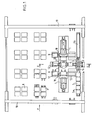
- La Figure 1 est une vue en plan de la machine;
- La Figure 2 en est une coupe suivant II-II de la Figure 1;
- La Figure 3 en est une vue suivant la flèche F de la Figure 1.
- Figure 1 is a plan view of the machine;
- Figure 2 is a section along II-II of Figure 1;
- Figure 3 is a view along arrow F of Figure 1.
Telle qu'elle est représentée au dessin, la machine convertible selon l'invention comprend deux unités d'usinage 1 disposées en vis à vis et entre lesquelles est disposée une table 2 avec plateau tournant indexable. Cette table est destinée à recevoir des palettes dont chacune porte une pièce à usiner, une palette et la pièce qu'elle supporte étant désignées au dessin par la référence 3, et est munie de moyens de serrage 4 propres à maintenir un ensemble palette-pièce sur la table.As shown in the drawing, the convertible machine according to the invention comprises two machining units 1 arranged opposite and between which is a table 2 with indexable turntable. This table is intended to receive pallets, each of which carries a workpiece, a pallet and the part it supports being designated in the drawing by the ref rence 3, and is provided with clamping means 4 suitable for maintaining a pallet-piece assembly on the table.
Deux convoyeurs 5a et 5b pour les palettes 3 sont disposés parallèlement aux deux unités d'usinage 1, de part et d'autre d'un ascenseur 6 situé en regard de la table 2.Two
La machine comporte un magasin de stockage 8 pour des boîtiers ou têtes d'usinage 9 adaptables aux unités d'usinage 1, ainsi qu'un pont transporteur 10 muni de deux dispositifs de monte et baisse 11 et destiné à prélever les boîtiers 9 du magasin de stockage 8 pour les déposer sur des tables d'attente 12 prévues de part et d'autre de chaque unité d'usinage 1 et inversement pour reprendre les boîtiers ayant été utilisés pour les ramener au magasin de stockage. Des barres 18 mobiles en translation permettent d'amener un boîtier d'usinage 9 d'une table d'usinage 12 à l'unité d'usinage adjacente ainsi que de ramener sur une table 12 un boîtier venant d'être utilisé.The machine comprises a storage magazine 8 for boxes or machining
L'ascenseur 6 fait partie d'un circuit interne d'usinage disposé dans un plan perpendiculaire à l'axe des unités d'usinage 1 et comportant, outre l'ascenseur, un descenseur 13, ce descenseur et l'ascenseur 6 étant disposés de part et d'autre de l'axe de la table 2, et un circuit horizontal qui passe sous cette table 2 et peut comporter une zone de lavage et de soufflage 14 ainsi qu'une zone 15 d'évacuation des copeaux.The
Un dispositif 16 permet d'amener une palette avec la pièce qu'elle supporte, d'un convoyeur 5a ou 5b sur l'ascenseur 6 en position haute et inversement de l'ascenseur sur l'un des convoyeurs. Une barre 17 permet de déplacer une palette se trouvant sur l'ascenseur pour l'amener sur la table 2, ou bien pour amener sur le descenseur 13 une palette se trouvant sur la table.A
La machine qui vient d'être décrite est utilisée de la manière suivante.The machine which has just been described is used in the following manner.
Des palettes 3, en nombre égal à celui d'une rafale, par exemple cinq, se trouvent sur l'un des convoyeurs, par exemple le convoyeur 5a.Pallets 3, in number equal to that of a burst, for example five, are located on one of the conveyors, for example the conveyor 5a.
Chacune des palettes de la rafale est amenée successivement sur l'ascenseur 6, en position haute, puis sur la table 2 où elle est usinée. Après usinage, elle est remplacée sur la table 2 par une deuxième palette de la rafale pendant qu'elle passe dans le descenseur 13; elle se déplace ensuite horizontalement sous la table, en traversant la zone de lavage/soufflage 14 et la zone d'évacuation des copeaux 15, et est ramenée en position par l'ascenseur 6. Le cycle est achevé. Si l'usinage n'est pas terminé, la palette avec sa pièce refait un cycle, les boîtiers 9 ayant été changés. Ce deuxième cycle sera nécessaire pour les cinq pièces de la rafale. Si l'usinage est terminé, elle est évacuée sur le même convoyeur 5a, puis immédiatement remplacée par une autre palette munie de sa pièce à usiner, venant du convoyeur 5b et appartenant à une autre rafale.Each of the pallets of the burst is brought successively to the
Lorsque les pièces d'une même rafale sont les unes dans le circuit intérieur et les autres sur le convoyeur 5a qui les a amenées et les reprend ensuite, des pièces de la rafale suivante sont amenées au poste d'usinage ou dans le circuit intérieur en provenance du convoyeur 5b. Chacun des deux convoyeurs assure donc alternativement l'alimentation d'une rafale, puis son évacuation pendant que l'autre convoyeur assure respectivement l'évacuation de la rafale précédente et l'alimentation de la rafale suivante.When the parts of the same burst are one in the internal circuit and the other on the conveyor 5a which brought them and then takes them up again, parts of the following burst are brought to the machining station or in the internal circuit in origin of the
Comme chaque unité d'usinage 1 comporte deux tables d'attente 12, l'une d'elles peut être utilisée pour recevoir un boîtier 9 en attente de montage dans l'unité alors que l'autre peut être utilisée pour recevoir un boîtier en attente de retour au magasin 8. Tous les transports de boîtiers peuvent ainsi être effectués pendant qu'un autre boîtier est en cours d'utilisation, donc en temps masqué.As each machining unit 1 has two waiting tables 12, one of them can be used to receive a
Chaque palette 3 est codée suivant l'opération à réaliser, à son arrivée dans la zone d'usinage 2; le code sera lu et donnera instruction au pont transporteur 10 de choisir le boîtier 9 capable de l'opération.Each pallet 3 is coded according to the operation to be carried out, on its arrival in the
Claims (6)
caractérisée en ce qu'elle comprend un circuit interne d'usinage passant par la table d'usinage (2) et pouvant contenir autant de supports avec leurs pièces que la rafale comporte de pièces.2. Machine according to claim 1,
characterized in that it comprises an internal machining circuit passing through the machining table (2) and being able to contain as many supports with their parts as the burst comprises of parts.
caractérisée en ce que le circuit interne d'usinage comprend un descenseur (13) propre à amener une pièce venant de subir une opération d'usinage, à un niveau situé en dessous de la table d'usinage (2), des zones de travail (14 et 15), et un ascenseur (6) pour ramener la pièce au niveau de la table.3. Machine according to claim 2,
characterized in that the internal machining circuit comprises a descender (13) suitable for bringing a workpiece which has just undergone a machining operation, to a level situated below the machining table (2), working areas (14 and 15), and an elevator (6) to bring the piece back to the level of the table.
caractérisée en ce qu'elle comporte deux convoyeurs (5a et 5b) disposés parallèlement aux unités d'usinage, des moyens de distribution pour faire passer chaque pièce d'un convoyeur au circuit d'usinage et de ce circuit d'usinage à un convoyeur.4. Machine according to claim 2 or 3,
characterized in that it comprises two conveyors (5a and 5b) arranged parallel to the machining units, distribution means for passing each piece from a conveyor to the machining circuit and from this machining circuit to a conveyor .
Applications Claiming Priority (2)
| Application Number | Priority Date | Filing Date | Title |
|---|---|---|---|
| FR8402788 | 1984-02-10 | ||
| FR8402788A FR2559412B1 (en) | 1984-02-10 | 1984-02-10 | CONVERTIBLE SEQUENTIAL PHASE MACHINE |
Publications (2)
| Publication Number | Publication Date |
|---|---|
| EP0154571A1 true EP0154571A1 (en) | 1985-09-11 |
| EP0154571B1 EP0154571B1 (en) | 1988-07-13 |
Family
ID=9301333
Family Applications (1)
| Application Number | Title | Priority Date | Filing Date |
|---|---|---|---|
| EP85400131A Expired EP0154571B1 (en) | 1984-02-10 | 1985-01-28 | Machining centre for sequential machining |
Country Status (5)
| Country | Link |
|---|---|
| US (1) | US4621408A (en) |
| EP (1) | EP0154571B1 (en) |
| JP (1) | JPS60186308A (en) |
| DE (1) | DE3563704D1 (en) |
| FR (1) | FR2559412B1 (en) |
Cited By (7)
| Publication number | Priority date | Publication date | Assignee | Title |
|---|---|---|---|---|
| EP0197364A1 (en) * | 1985-03-19 | 1986-10-15 | Heckler & Koch GmbH | Apparatus and method for handling work pieces |
| BE1005442A3 (en) * | 1991-10-14 | 1993-07-27 | Pegard Productics En Abrege Pe | Method and system for machining long elements, notably aeronautical metalelements |
| EP0681887A2 (en) * | 1994-03-07 | 1995-11-15 | Sony Corporation | Parts feeding apparatus and parts feeding process |
| EP1675422A1 (en) | 2004-12-22 | 2006-06-28 | Research In Motion Limited | System and Method for Redirecting Communications for a Mobile Device |
| CN110480051A (en) * | 2019-08-20 | 2019-11-22 | 青岛雷沃工程机械有限公司 | A kind of loading machine crossbeam processing unit (plant) and method |
| CN110496984A (en) * | 2019-09-05 | 2019-11-26 | 中擎电机有限公司 | Motor housing aperture ancillary equipment |
| CN111958247A (en) * | 2020-07-09 | 2020-11-20 | 宁波亿诺智能装备有限公司 | Automatic camshaft machining device |
Families Citing this family (5)
| Publication number | Priority date | Publication date | Assignee | Title |
|---|---|---|---|---|
| US4679297A (en) * | 1986-05-15 | 1987-07-14 | Gmf Robotics Corporation | Method for changing the tooling in a robot-based system and system utilizing same |
| US4870592A (en) * | 1988-02-01 | 1989-09-26 | Lampi Wayne J | Manufacturing system with centrally disposed dynamic buffer region |
| DE4108039A1 (en) * | 1991-03-13 | 1992-09-17 | Doerries Scharmann Gmbh | Tool-workpiece magazine and changer for machining centre - has two carriers operating independently on track loop connecting changer and magazines |
| US5321874A (en) * | 1992-07-31 | 1994-06-21 | Ford Motor Company | Multi-positioner machining system |
| DE10342677B4 (en) * | 2003-09-16 | 2006-04-20 | Holger Sprenger | Decoupling and synchronization module |
Citations (6)
| Publication number | Priority date | Publication date | Assignee | Title |
|---|---|---|---|---|
| CH148313A (en) * | 1930-10-02 | 1931-07-15 | Oerlikon Maschf | Process for carrying out fluid work in workshops by means of an endless conveyor device. |
| CH342816A (en) * | 1958-04-11 | 1959-11-30 | Posalux Frautschi & Monney | Machine tool comprising a transfer device |
| DE1506893A1 (en) * | 1966-05-27 | 1969-08-28 | Montres Rotary S A Fab De | Device for the successive transport of watch parts to be processed |
| DE3134195A1 (en) * | 1981-08-29 | 1983-03-10 | E.G.O. Elektro-Geräte AG, 6301 Zug | ASSEMBLY LINE WITH SEVERAL WORKPLACES |
| EP0076231A2 (en) * | 1981-09-24 | 1983-04-06 | Franz Schäfer | Method and apparatus for the serial treatment and/or the assembly of workpieces |
| GB2127765A (en) * | 1982-06-04 | 1984-04-18 | 600 Group Public Limited Compa | Conveying workpieces |
Family Cites Families (10)
| Publication number | Priority date | Publication date | Assignee | Title |
|---|---|---|---|---|
| DE1627020B2 (en) * | 1967-04-05 | 1973-02-22 | Wollenhaupt, Jakob, Wollenhaupt geb Stang, Agnes, 5000 Köln | TRANSFER ROAD COMPOSED FROM UNITS |
| GB1254446A (en) * | 1967-11-20 | 1971-11-24 | Sundstrand Corp | Machine tool control system |
| US3576540A (en) * | 1967-11-20 | 1971-04-27 | Sundstrand Corp | Plural machine tool and part handling control system |
| US3543392A (en) * | 1967-12-15 | 1970-12-01 | Cincinnati Milacron Inc | Machine tools having conveyor means extending therebetween and carrying pallet means which are selectively connectable to the machine tools |
| DE2000998A1 (en) * | 1970-01-10 | 1971-07-15 | Hueller Gmbh K | Workpiece manufacturing and machining facility |
| US3796327A (en) * | 1972-07-14 | 1974-03-12 | R Meyer | Manufacturing system |
| JPS5142280B2 (en) * | 1972-08-01 | 1976-11-15 | ||
| DE2839992A1 (en) * | 1978-09-14 | 1980-04-03 | Schuler Gmbh L | TOOL CHANGE DEVICE |
| DE3018358A1 (en) * | 1980-05-14 | 1981-11-19 | Translift AG, 6010 Kriens, Luzern | DEVICE FOR STORING AND TRANSPORTING LARGE TOOLS, ESPECIALLY DRILLING AND MILLING HEADS |
| US4711016A (en) * | 1982-11-19 | 1987-12-08 | Werner And Kolb Werkzeugmaschinen Gmbh | Flexible manufacturing unit |
-
1984
- 1984-02-10 FR FR8402788A patent/FR2559412B1/en not_active Expired
-
1985
- 1985-01-28 DE DE8585400131T patent/DE3563704D1/en not_active Expired
- 1985-01-28 EP EP85400131A patent/EP0154571B1/en not_active Expired
- 1985-02-06 US US06/698,764 patent/US4621408A/en not_active Expired - Fee Related
- 1985-02-12 JP JP60025078A patent/JPS60186308A/en active Pending
Patent Citations (6)
| Publication number | Priority date | Publication date | Assignee | Title |
|---|---|---|---|---|
| CH148313A (en) * | 1930-10-02 | 1931-07-15 | Oerlikon Maschf | Process for carrying out fluid work in workshops by means of an endless conveyor device. |
| CH342816A (en) * | 1958-04-11 | 1959-11-30 | Posalux Frautschi & Monney | Machine tool comprising a transfer device |
| DE1506893A1 (en) * | 1966-05-27 | 1969-08-28 | Montres Rotary S A Fab De | Device for the successive transport of watch parts to be processed |
| DE3134195A1 (en) * | 1981-08-29 | 1983-03-10 | E.G.O. Elektro-Geräte AG, 6301 Zug | ASSEMBLY LINE WITH SEVERAL WORKPLACES |
| EP0076231A2 (en) * | 1981-09-24 | 1983-04-06 | Franz Schäfer | Method and apparatus for the serial treatment and/or the assembly of workpieces |
| GB2127765A (en) * | 1982-06-04 | 1984-04-18 | 600 Group Public Limited Compa | Conveying workpieces |
Non-Patent Citations (6)
| Title |
|---|
| MACHINES PRODUCTION, no. 195, 29 mars 1978, pages 13,15,17,19,21,23,25-27, Sofetec, Boulogne, Seine, FR; "CN: du CU aux systèmes modulaires souples d'usinage" * |
| MACHINES PRODUCTION, no. 349, 27 avril 1983, pages 19-26, Sofetec, Boulogne, Seine, FR; "F. WERNER: spécialiste de la cellule flexible" * |
| VDI-ZEITSCHRIFT, vol. 121, no. 3, février 1979, pages 83-95, Düsseldorf, DE; G. VETTIN: "Flexibel automatisierte Fertigungsanlagen" * |
| WERKSTATT UND BETRIEB, vol. 107, no. 12, décembre 1974, pages 717-730, Munich, DE; J. KLAAR et al.: "WB-Lagebericht: Einsatz automatisch wechselbarer Mehrspindelbohrköpfe" * |
| WERKSTATT UND BETRIEB, vol. 108, no. 12, décembre 1975, pages 795-796, Munich, DE; "Modell eines flexiblen Fertigungssystems" * |
| WERKSTATTSTECHNIK, vol. 63, no. 4, avril 1973, pages 199-206, Springer-Verlag, Berlin, DE; P. SCHARF et al.: "Integrierte, flexible Fertigungssysteme" * |
Cited By (10)
| Publication number | Priority date | Publication date | Assignee | Title |
|---|---|---|---|---|
| EP0197364A1 (en) * | 1985-03-19 | 1986-10-15 | Heckler & Koch GmbH | Apparatus and method for handling work pieces |
| BE1005442A3 (en) * | 1991-10-14 | 1993-07-27 | Pegard Productics En Abrege Pe | Method and system for machining long elements, notably aeronautical metalelements |
| EP0681887A2 (en) * | 1994-03-07 | 1995-11-15 | Sony Corporation | Parts feeding apparatus and parts feeding process |
| EP0681887A3 (en) * | 1994-03-07 | 1997-04-23 | Sony Corp | Parts feeding apparatus and parts feeding process. |
| US5672040A (en) * | 1994-03-07 | 1997-09-30 | Sony Corporation | Parts feeding apparatus and parts feeding process |
| EP1675422A1 (en) | 2004-12-22 | 2006-06-28 | Research In Motion Limited | System and Method for Redirecting Communications for a Mobile Device |
| CN110480051A (en) * | 2019-08-20 | 2019-11-22 | 青岛雷沃工程机械有限公司 | A kind of loading machine crossbeam processing unit (plant) and method |
| CN110496984A (en) * | 2019-09-05 | 2019-11-26 | 中擎电机有限公司 | Motor housing aperture ancillary equipment |
| CN110496984B (en) * | 2019-09-05 | 2020-10-20 | 中擎电机有限公司 | Motor housing trompil auxiliary assembly |
| CN111958247A (en) * | 2020-07-09 | 2020-11-20 | 宁波亿诺智能装备有限公司 | Automatic camshaft machining device |
Also Published As
| Publication number | Publication date |
|---|---|
| EP0154571B1 (en) | 1988-07-13 |
| US4621408A (en) | 1986-11-11 |
| DE3563704D1 (en) | 1988-08-18 |
| FR2559412B1 (en) | 1986-07-18 |
| JPS60186308A (en) | 1985-09-21 |
| FR2559412A1 (en) | 1985-08-16 |
Similar Documents
| Publication | Publication Date | Title |
|---|---|---|
| KR100371763B1 (en) | Machining centre | |
| TWI691012B (en) | Wafer processing system | |
| EP0154571A1 (en) | Machining centre for sequential machining | |
| CA2209284C (en) | Assembly shop for sheet metal parts | |
| FR2518971A1 (en) | LOADING / UNLOADING DEVICE OF MACHINE TOOLS OR THE LIKE | |
| FR2507521A1 (en) | MACHINING INSTALLATION TYPE TRANSFER | |
| CH648232A5 (en) | MACHINE TOOL. | |
| US6464623B1 (en) | Tool storage and tool exchange device of a machining machine-tool and operating process of such a device | |
| EP0198847B1 (en) | Modular machine tool for series machining of parts in a bar | |
| MX9706519A (en) | Machine tool module with cutting tool and superimposed workpiece-carrying platen. | |
| FR2702165A1 (en) | Single-point loading / unloading system for a dual ram rotary blind spline broaching machine. | |
| JPH05338728A (en) | Wafer carrying method and device thereof | |
| JP4859012B2 (en) | Machine tool with transport chain | |
| EP0864398A1 (en) | Machine tool with tool store with improved capacity and tool store for equipping a machine tool | |
| JPS59166444A (en) | Device for removing chips on automatic processing line with machine tool | |
| US6293386B1 (en) | Leadframe transport and method therefor | |
| FR2806952A1 (en) | Machining center including a gripping and supporting member adapted to firmly hold the workpiece from the top during the machining operation and to facilitate the removal of chips from the machining area | |
| CN213053953U (en) | Milling device for milling and grinding milling cutter on side | |
| KR102469572B1 (en) | Apparatus for loading/unloading a workpiece into/from a turning center | |
| JP3909648B2 (en) | lathe | |
| FR2602166A1 (en) | Improvements to transfer machines | |
| FR2668730A1 (en) | Device and method for changing tools on moving gantry machine tools | |
| FR2705266A1 (en) | Workcell with two machine tools and a common tool changer. | |
| SU603562A1 (en) | Automatic machining line | |
| FR2848488A1 (en) | Mechanical object e.g. crank case manufacturing workshop, has transfer unit to shift objects parallel to direction of row of treatment unit, from another transfer unit to treatment unit, which are held parallel and adjacent to one another |
Legal Events
| Date | Code | Title | Description |
|---|---|---|---|
| PUAI | Public reference made under article 153(3) epc to a published international application that has entered the european phase |
Free format text: ORIGINAL CODE: 0009012 |
|
| AK | Designated contracting states |
Designated state(s): DE GB IT |
|
| 17P | Request for examination filed |
Effective date: 19850725 |
|
| 17Q | First examination report despatched |
Effective date: 19861028 |
|
| GRAA | (expected) grant |
Free format text: ORIGINAL CODE: 0009210 |
|
| AK | Designated contracting states |
Kind code of ref document: B1 Designated state(s): DE GB IT |
|
| ITF | It: translation for a ep patent filed | ||
| GBT | Gb: translation of ep patent filed (gb section 77(6)(a)/1977) | ||
| REF | Corresponds to: |
Ref document number: 3563704 Country of ref document: DE Date of ref document: 19880818 |
|
| PG25 | Lapsed in a contracting state [announced via postgrant information from national office to epo] |
Ref country code: GB Effective date: 19890128 |
|
| PLBE | No opposition filed within time limit |
Free format text: ORIGINAL CODE: 0009261 |
|
| STAA | Information on the status of an ep patent application or granted ep patent |
Free format text: STATUS: NO OPPOSITION FILED WITHIN TIME LIMIT |
|
| 26N | No opposition filed | ||
| GBPC | Gb: european patent ceased through non-payment of renewal fee | ||
| PG25 | Lapsed in a contracting state [announced via postgrant information from national office to epo] |
Ref country code: DE Effective date: 19891003 |