EP0154191B1 - Infusionssystem mit mehreren Fluid-Eingängen und mindestens einem Patienten-Ausgang - Google Patents
Infusionssystem mit mehreren Fluid-Eingängen und mindestens einem Patienten-Ausgang Download PDFInfo
- Publication number
- EP0154191B1 EP0154191B1 EP85101328A EP85101328A EP0154191B1 EP 0154191 B1 EP0154191 B1 EP 0154191B1 EP 85101328 A EP85101328 A EP 85101328A EP 85101328 A EP85101328 A EP 85101328A EP 0154191 B1 EP0154191 B1 EP 0154191B1
- Authority
- EP
- European Patent Office
- Prior art keywords
- fluid
- pumping
- infusion system
- infusion
- data
- Prior art date
- Legal status (The legal status is an assumption and is not a legal conclusion. Google has not performed a legal analysis and makes no representation as to the accuracy of the status listed.)
- Expired - Lifetime
Links
Images


Classifications
-
- A—HUMAN NECESSITIES
- A61—MEDICAL OR VETERINARY SCIENCE; HYGIENE
- A61M—DEVICES FOR INTRODUCING MEDIA INTO, OR ONTO, THE BODY; DEVICES FOR TRANSDUCING BODY MEDIA OR FOR TAKING MEDIA FROM THE BODY; DEVICES FOR PRODUCING OR ENDING SLEEP OR STUPOR
- A61M5/00—Devices for bringing media into the body in a subcutaneous, intra-vascular or intramuscular way; Accessories therefor, e.g. filling or cleaning devices, arm-rests
- A61M5/14—Infusion devices, e.g. infusing by gravity; Blood infusion; Accessories therefor
- A61M5/142—Pressure infusion, e.g. using pumps
- A61M5/14212—Pumping with an aspiration and an expulsion action
- A61M5/14224—Diaphragm type
-
- A—HUMAN NECESSITIES
- A61—MEDICAL OR VETERINARY SCIENCE; HYGIENE
- A61M—DEVICES FOR INTRODUCING MEDIA INTO, OR ONTO, THE BODY; DEVICES FOR TRANSDUCING BODY MEDIA OR FOR TAKING MEDIA FROM THE BODY; DEVICES FOR PRODUCING OR ENDING SLEEP OR STUPOR
- A61M5/00—Devices for bringing media into the body in a subcutaneous, intra-vascular or intramuscular way; Accessories therefor, e.g. filling or cleaning devices, arm-rests
- A61M5/14—Infusion devices, e.g. infusing by gravity; Blood infusion; Accessories therefor
- A61M5/168—Means for controlling media flow to the body or for metering media to the body, e.g. drip meters, counters ; Monitoring media flow to the body
- A61M5/172—Means for controlling media flow to the body or for metering media to the body, e.g. drip meters, counters ; Monitoring media flow to the body electrical or electronic
-
- A—HUMAN NECESSITIES
- A61—MEDICAL OR VETERINARY SCIENCE; HYGIENE
- A61M—DEVICES FOR INTRODUCING MEDIA INTO, OR ONTO, THE BODY; DEVICES FOR TRANSDUCING BODY MEDIA OR FOR TAKING MEDIA FROM THE BODY; DEVICES FOR PRODUCING OR ENDING SLEEP OR STUPOR
- A61M5/00—Devices for bringing media into the body in a subcutaneous, intra-vascular or intramuscular way; Accessories therefor, e.g. filling or cleaning devices, arm-rests
- A61M5/14—Infusion devices, e.g. infusing by gravity; Blood infusion; Accessories therefor
- A61M5/142—Pressure infusion, e.g. using pumps
- A61M2005/14208—Pressure infusion, e.g. using pumps with a programmable infusion control system, characterised by the infusion program
-
- A—HUMAN NECESSITIES
- A61—MEDICAL OR VETERINARY SCIENCE; HYGIENE
- A61M—DEVICES FOR INTRODUCING MEDIA INTO, OR ONTO, THE BODY; DEVICES FOR TRANSDUCING BODY MEDIA OR FOR TAKING MEDIA FROM THE BODY; DEVICES FOR PRODUCING OR ENDING SLEEP OR STUPOR
- A61M5/00—Devices for bringing media into the body in a subcutaneous, intra-vascular or intramuscular way; Accessories therefor, e.g. filling or cleaning devices, arm-rests
- A61M5/14—Infusion devices, e.g. infusing by gravity; Blood infusion; Accessories therefor
- A61M5/168—Means for controlling media flow to the body or for metering media to the body, e.g. drip meters, counters ; Monitoring media flow to the body
- A61M5/16804—Flow controllers
- A61M5/16827—Flow controllers controlling delivery of multiple fluids, e.g. sequencing, mixing or via separate flow-paths
-
- Y—GENERAL TAGGING OF NEW TECHNOLOGICAL DEVELOPMENTS; GENERAL TAGGING OF CROSS-SECTIONAL TECHNOLOGIES SPANNING OVER SEVERAL SECTIONS OF THE IPC; TECHNICAL SUBJECTS COVERED BY FORMER USPC CROSS-REFERENCE ART COLLECTIONS [XRACs] AND DIGESTS
- Y10—TECHNICAL SUBJECTS COVERED BY FORMER USPC
- Y10S—TECHNICAL SUBJECTS COVERED BY FORMER USPC CROSS-REFERENCE ART COLLECTIONS [XRACs] AND DIGESTS
- Y10S128/00—Surgery
- Y10S128/13—Infusion monitoring
Definitions
- the present invention relates to an infusion system in accordance with the prior art portion of claim 1.
- Intravenous infusion therapy is prescribed where it is desirable to administer medications and other fluids directly into the circulatory system of a patient. It is estimated that approximately forty percent of U.S. hospital patients presently receive some form of infusion therapy and it is expected that the proportion will grow in the future due to the improved health care that results from such therapy.
- plural gravity flow controllers and plural independent electronic pumps have heretofore been employed for this purpose.
- the plural gravity flow controllers are disadvantageous, among other things, due to the increased possibility of infection occasioned by multiple IV venipuncture; due to the flow inaccuracies occasioned, among othe things, by patient movement induced tube occlusion or tubing shape changes; due to the considerable labor and time required from a nurse or other health practitioner to manually control the plural gravity flow controllers in accordance with a prescribed course of therapy; due to clutter around the patient; and due to the possibility of out-of-control infusion occasioned by a failure of one or more of the gravity flow controllers.
- the plural independent pumps are disadvantageous, among other things, due to the clutter around the patient occasioned by the use of plural pumps; due to the increased possibility of infection occasioned by multiple IV venipuncture; due to the comparatively high cost of procuring and maintaining several pumps for each such patient; due to the incapability of the heretofore known pumps to administer more than two infusates in time sequence without additional pumps; due to the incapability of the heretofore known pumps to administer more than two infusates in time sequence without additional pumps; due to the incapability of the heretofore known pumps to administer dilutions; due to the considerable time and labor required by the health practitioner to program and to supervise the plural indepedent pumps; and due to the comparatively high cost incurred in maintaining an inventory of tubes and administration sets that must be replaced periodically to avoid infection for each pump, fluid, and patient, often amounting on an annual basis to about one half the cost of the pumps themselves.
- EP-A2-0013334 discloses the system for sequentially pumping through plural sources of fluid by opening and closing valves. Each valve is sequentially opened for a fixed time and a fluid is pumped through a fixed rate.
- the present invention is based on the object of providing an infusion system of the above-mentioned type offering a higher degree of flexibility when administering several fluids to a patient.
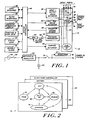
- the system 10 includes a disposable cassette generally designated 12 to be described having a fluid channel 14.
- a plurality of fluid input ports 16, four (designated “A”, “B”, “C”, and “D") being specifically illustrated, are connected to the fluid flow channel 14 through a corresponding one of a plurality of valves 18.
- Each fluid input port 16 is directly connectable to a elected fluid to be infused, not shown.
- the cassette 12 includes a pumping chamber generally designated 20 connected to the fluid channel 14, and a pressure chamber generally designated 22 connected to the pumping chamber 20 via a fluid flow channel 24.
- a patient output port 26 is connected in a fluid flow path to the pressure chamber 22 via a valve 28, and a vent output port 30 is connected to the pressure chamber 22 in a fluid flow path via a valve 32.
- the patient output port 26 is directly connectable to a patient via a patient output line, not shown.
- the vent output port 30 is directly connectable, for example, to a collection bag to be described or other fluid sink.
- An input and output valve actuator 34 to be described is operatively connected to the plural fluid input valves 18 and to the patient output valve 28.
- the actuator 34 is operative to select the "open” and the "closed” state of the valves 18, 28, and therewith to control fluid flow from the corresponding fluid input ports 16 into the cassette 12 and to control fluid flow out of the cassette into the patient.
- the actuator 34 is preferably operative to prevent the input and output valves from being simultaneously in the "open” condition to eliminate the possibility of unintended gravity flow infusion.
- a separate actuator to be described is preferably connected to the output valve 28 to maintain the patient output port and any selected input port "open".
- a vent valve actuator 36 to be described is operatively connected to the vent valve 32.
- the actuator 36 is operative to select the "open” and the “closed” state of the valve 32, and therewith to control fluid flow from the cassette 12 into the collection bag to remove air from the fluid flow channel during initial setup and during operation of the infusion system.
- a cassette-locked-in-place sensor 38 is operative to provide a signal that represents that the cassette is in its intended operating position to prevent fluid leakage and unintended infusion.
- a pressure transducer 40 to be described is operatively connected to the pressure chamber 22.
- the pressure transducer 40 is operative to provide an analog signal representative of the pressure in the pressure chamber 22.
- An amplifier 42 amplifies the analog signal, and a analog to digital converter (ADC) 44 converts the amplified analog signal into digital data.
- ADC analog to digital converter
- the digital data provides information representative of air in line, of actual infusion volume relative to nominal infusion volume, of patient output line occlusion, and of fluid level remaining to be infused through corresponding fluid input ports 16.
- a pumping actuator 46 to be described is operatively connected to the pump chamber 20.
- the pumping actuator 46 is operative to controllably fill and pump fluid from the pumping chamber 20 into either the patient output port 26 or the vent output port 30 in dependence on the state of actuation of the valves 28 and 32.
- the pumping actuator 46 is operative to precisely administer an intended amount of fluid in an intended time interval from any one or more of the fluid input ports 16 in any order either in time sequence or in time overlap to dilute the concentration of a selected infusate.
- An operator interactive display 50 is operatively connected to the system controller 48.
- the display 50 is operative to display one of plural display templates to be described that individually correspond to the modes of operation of the system controller 48, to display system status information, to display operator prompts to assist the operator in selecting volume, rate, and time of infusion, and to display various error and alarm conditions.
- the modes includes a flush mode template, a prime mode template, an override mode template, a primary mode template, and a piggyback mode template.
- Operator data and function keys 52 to be described are operatively connected to the system controller 48.
- the data and function keys 52 are operative for selecting the rate, volume, and time of infusion; for selecting the state of operation of the infusion system including the override mode, the priming mode, and the normal-on mode; for controlling the operator interactive display; and for selecting maximum occlusion pressure, minimum infusion rate, and total fluid volume to be administered.
- LED's 54 are operatively connected to the system controller 48.
- the LED's 54 are operative to provide a visual indication of the various alarm conditions and of battery status.
- An audible alarm 56 is operatively connected to the system controller 48 to provide an audible indication of alarm condition.
- One or more slave interfaces 58 are operatively connected to the system controller 48. Each slave interface 58 is connectable to an auxiliary pump to be described that may be slaved to the system controller 48 to administer the infusion of an incompatible infusate.
- a universal asynchronous receiver transmitter interface (UART) 60 is operatively connected to the system controller 48. The UART 60 may be connected to any suitable peripheral device such as a display terminal or a computerized central nurse station.
- a rectifier and regulator 62 is connected to a source of AC power 64 such as a conventional hospital outlet via a fusible link 66.
- a regulator 67 is connected to the rectifier and regulator 62 via a switch 70.
- the rectifier and regulator 62 and regulator 67 provide power to the infusion system in normal operation,
- a battery 68 provides power to the infusion system either in the event of a power failure or in the event that it is desirable to move the patient such as between an intensive care unit and an operating room.
- the battery 68, the rectifier and regulator 62, and regulator 67 are operatively connected to the ADC 44 designated "Voltage Inputs".
- the system controller 48 is operative in response to a fall in the output of the converter signal from the regulators below a predetermined value to switch to the battery 68, and the controller 48 is operative to activate a corresponding status LED to provide a low battery indication whenever the level of the battery falls below a predetermined level.
- Fig. 2 generally designated at 72 is state diagram illustrating the principal operating states of the system controller 48 (Fig. 1).
- an "off" state 74 the system controller 48 is waiting, its clock is running, and no pumping is occurring.
- a "programming" state 76 data is selectably input to specify the time, rate, and volume for fluid to be administered from any one or more of the plural fluid input ports 16 (Fig. 1), and data is selectably input to specify current time, KVO rate, maximum occlusion pressure, and total fluid rate and volume. Data entered is selectably displayable in the "programming" state on the operator interactive display for operator review.
- an “override” state 78 the system controller 48 (Fig. 1) is operative in a manual override mode.
- a "priming” state 80 data is selectably input to specify an input line as a priming line.
- the system controller is operative in the "priming" state to allow fluid to flow by gravity from a selected input port through the cassette 12 (Fig. 1) and either into the collection bag to remove air from the cassette or through the output port and into the patient output line prior to venipuncture to remove air from the patient line.
- fluid may also be primed by pumping.
- the system controller is operative to automatically pump fluid from the input ports at the rates, volumes, and times specified in the "programming" state.
- the system controller in the "programming" state for a particular one of the plural fluid input ports may also be in the "auto-on” state 82 for the other ones of the plural fluid input ports that may be being infused at a selected rate, volume, and time into the patient in accordance with a desired course of therapy.
- the system controller is operative to display on the operator interactive display data representative of the total quantity of fluid administered to a patient from the plural fluid input ports at a given time. Data accumulated in the history state 84 can advantageously be employed with a computerized hospital information system.
- a "slave pump controller" mode 86 the system controller is operative to control one or more auxiliary pumps.
- the auxiliary pumps can advantageously be employed to control one or more additional infusions for the administration of an incompatible drug without losing the benefit of integrated infusion control and data accumulation.
- Fig. 3A generally designated at 88 is an isometric view illustrating a preferred embodiment of a housing of the infusion system having plural fluid input ports and at least one patient output port according to the present invention.
- the housing 88 is mounted to a conventional IV pole 92 such that its front panel generally designated 90 to be described is oriented at an angle selected to provide ease of operator access, preferably 45°.
- a disposable cassette generally designated 94 to be described is slidably mounted in a channel generally designated 96 provided therefor on one side of the housing 88.
- the cassette 94 is oriented at the same angle of inclination to the vertical to allow both pumping with slight quantities of air in the fluid flow path and the expeditious removal of air from the fluid flow path as appears more fully below.
- a locking lever 100 having a safety mechanism 102 to be described is pivotally mounted to the housing 88.
- the lever 100 is operatively connected to a rod to be described that is mounted for reciprocating motion in the housing 88.
- the rod is operate to removably retain the cassette 94 in the channel 96 on the side of the housing 88 in a manner to be described.
- the cassette 94 includes four fluid input ports 104, 106, 108, and 110, a patient output port 112, and a vent output port 114.
- a plurality of fluid containers are positioned a predetermined vertical distance above the housing 88 and directly connected to corresponding of the fluid input ports, two such fluid containers 116, 118 connected to the input ports 104, 106 being specifically illustrated. It will be appreciated that two additional fluid containers, bags, or syringes, not shown, may be directly connected to the ports 108, 110.
- a plurality of indicating lines 119 are provided on the side of the housing.
- a patient output line 120 is connected to the output port 112, and a collection bag line 122 is connected between the vent output port 114 and a collection bag removably retained on the back of the housing 88, not shown.
- Fig. 3B generally designated at 124 is a plan view of a preferred embodiment of the front panel of the housing of the infusion system having plural fluid input ports and at least one patient output port according to the present invention.
- the front panel 124 includes an operator interactive display 126 for displaying one of a plurality of display templates to be described.
- the display 126 preferably is an 80 character LCD display commerically available, for example, from Epson.
- a plurality of display command keys designated by a dashed box 128 are provided on the front panel 124.
- the display keys 128 include a clear entry key 130, a last entry key 132, a next entry key 134, and an enter key 136.
- the clear entry key 130 when pressed clears inadvertently or mistakenly entered data
- the last entry key 132 when pressed moves a display cursor to a previous field of a display
- the next entry key 134 when pressed moves a display cursor to the next field of a display
- the enter key 136 enters the data entered into the various fields of a display into system memory.
- a plurality of rate, volume, and time command keys designated by a dashed box 138 are provided on the front panel 124.
- the rate, volume, and time command keys 138 include a primary infusion key 140, a piggyback infusion key 142, a flush key 144, and a reset key 146.
- the primary infusion key 140 when pressed selects the programming state 76 (Fig. 2), and displays a primary infusion template for each fluid input that allows selection of the rate, volume, and time sequence of infusion from any one or more of the plural fluid input ports in any order to implement a prescribed course of therapy that calls for the nonsimultaneous infusion of primary fluids at the same or different rates in a predetermined time sequence.
- the primary infusion template preferably has the following format.
- any one of keys 162, 160, 166, 168 to be described If the operator selects the key 168, designated "A", for example, an "A" appears in the first data field of the primary infusion template.
- the operator then presses the "next" key 134 and the display cursor moves to the second data field of the infusion primary template.
- the operator selects either a key 176 or a key 178 to be described and a "yes” or a "no" appears in the second data field of the template. Call back when selected by pressing the "yes" key 176 specifies that the system operator is to be called back prior to beginning infusion on the selected line.
- the operator then presses the "next" key 136 again and the system controller is operative to display the following display template.
- the data fields of the templates are shown herein by either “dashed” underline or by “solid” underline. "Dashed” underline entry is optional.
- rate and volume are specified for the above template, the system controller can calculate duration and volume.
- the piggyback infusion key 142 when pressed, selects the "programming" state 76 (Fig. 2) and displays a piggyback infusion template that allows selection of the rate, volume, and time sequence from any one or more of the plural fluid input ports in any order to implement a course of therapy that calls for the intermittent infusion of one or more piggyback fluids either at regular repeat intervals or in time overlap to provide a dilution of the concentration of one of the infusates.
- Piggyback infusions are each preferably less than sixty minutes in duration.
- the piggyback infusion template preferably has the following format. The operator then presses any of keys 162, 164, 166, 168.
- the system controller After entering the data into the data fields and pressing the "next" key, the system controller is then operative to display the following display template.
- the first data field allows the operator to specify the volume of the fluid container for the "B" line
- the second data field allows the operator to select a fluid input line for dilution
- the third data field allows the operator to select diluent volume
- the fourth data field allows the operator to select diluent rate.
- the operator then presses the "enter” key 136 and the data is written into the corresponding address locations of the data file for that line.
- the flush key 144 when pressed is operative to allow the selection of one of the plural fluid input ports as a flushing line for buffering one infusate from another and to allow the selection of a variable flush quantity and rate selected to accommodate different lengths of the patient output line 120 (Fig. 3A).
- the flush display template preferably has the following format. The operator then presses a selected key 162, 164, 166, 168 to specify the flush line for the first data field, and the appropriate keys 170 to specify the rate and volume of flush for the second and third data fields. The operator then presses the "enter" key and the data is entered into the data file. During flushing, the system controller is operative to display the following display template.
- the reset key 146 when pressed allows the operator to clear a previous rate, time, and volume selection for each of the plural fluid input ports. If an infusion is in process when this key is pressed, the system controller is operative to display on the operator Interactive display 128 the following display template to prompt the operator to insure that the key has not accidently been pressed.
- a plurality of pump command keys designated by a dashed box 148 are provided on the front panel 124.
- the pump command keys 148 include a start key 150, a stop key 152, an override key 154, and a priming key 156.
- the start key 150 when pressed is operative to initiate a selected course of infusion therapy.
- the system controller is operative to display the following template if the start key 150 is pressed for a primary line.
- the first and second data fields of the start primary display template allows operator selection of the starting time of the selected line in machine time
- the third and fourth data fields allows operator selection of a specified time delay start
- the fifth data field allows operator selection of a start of the designated primary line after termination of infusion on another line. The operator then presses the "enter" key and the selected data is written into the data file address locations for that line.
- the system controller is operative to display the following display template if the start key 150 is pressed for a piggyback line.
- the first data field allows operator selection of the line.
- the second and the third data fields (hours, minutes) allow operator selection of a specified starting time.
- the fourth and fifth data fields allow operator selection of specified time delay start before the selected line is started. If no data is entered there, pumping starts at current system time. The operator then presses the "enter" key and the selected data is written into the data field address locations for that line.
- the stop key 152 when pressed is operative to terminate the desired course of infusion.
- the system controller is operative to display the following display template to ensure an intended stop.
- the data field for the display template allows operator selection of the appropriate line to be stopped, which, when entered, is written to the data file.
- the prime key 156 when pressed selects the priming state 80 (Fig. 2).
- the priming key 156 allows the operator to select any one of the fluid input ports to allow fluid to flow from the selected port through the cassette and into either the collection bag or patient output line.
- the corresponding valves are held open allowing fluid to flow as long as the selected line key is held down.
- the system controller is operative to display the following display template when the prime key is pressed.
- the first data field allows the system operator to select which input port is to be primed into the collection bag.
- the system controller is operative to continue the priming action from the selected line so long as the corresponding one of the keys 162, 164, 166, and 168 is manually maintained in a closed condition.
- the system controller is operative to display the following display template.
- the first data field of the template allows the operator to select which input port is to be primed into the patient line.
- the system controller is operative to prime the patient line as long as the corresponding key 162, 164, 166, and 168 is held down.
- Pressing the priming key followed by pressing any one of the keys 162, 164, 166, and 168 selects priming from the selected fluid input port through the cassette and into the collection bag.
- pressing the override key 154 and any one of the keys 162, 164, 166, and 168 selects operation in the override mode for the selected line.
- the keys 162, 164, 166, 168 are similarly operative when the primary infusion key 140, the piggyback key 142, and the flush key 144 are pressed.
- An IV flow sheet key 180 is provided on the front panel 124.
- the key 180 when pressed is operative to select the history state 84 (Fig. 2).
- the system controller is operative to display up-to-date total infusion volume.
- the system controller is operative to display the following display template when the key 180 is pressed.
- the data fields of the display template are selectably resettable by pressing the reset key 146 in the appropriate data field.
- An explain key 182 is provided on the front panel 124.
- the explain key 182 when pressed in sequence with any of the function keys described above provides an operator display template on the operator interactive display 126 that assists the operator in understanding the function of the corresponding key.
- Each key preferably should be held down within three seconds after the explain key is pressed to obtain an explanation of the key.
- Exemplary display templates are omitted for brevity of explication.
- a mute key 184 is provided on the front panel 124. The system controller is operative when the mute key 184 is pressed to silence the audible alarm.
- a plurality of status LED's designated by a dashed box 186 are provided on the front panel 124.
- the status LED's 186 include an AC power LED 188, a battery LED 190, and an alarm LED 192.
- the AC power LED 188 provides a visual indication that the infusion system is operative under AC power
- the battery LED 190 provides a visual indication that the infusion system is operative under internal battery power
- the alarm LED 186 provides a visual indication of either an alarm condition or an error condition.
- the system controller is operative to provide an alarm indication to indicate that infusion is complete on a line, to indicate that call back has been requested, to indicate an occlusion situation, to indicate air in line, to indicate a low battery condition, to indicate an out of place cassette, and to indicate that primary infusions are simultaneously scheduled.
- the system controller is operative to display the following display templates for each of the alarm conditions.
- the system controller is operative to provide an error indication to indicate pump failure and to indicate an out-of-range entry or invalid key.
- the corresponding error display templates preferably have the following formats.
- the system controller is operative to display the following "home" display template indicating system status whenever it does not display any of the above described display templates.
- the states for each of the lines will be either "OFF”, “PGM”, “ON”, “OVR”, or “KVO".
- OFF indicates that the corresponding line is in an inactive state
- PGM indicates that the corresponding line has been programmed to pump at a selected rate, volume, and time
- ON indicates that the corresponding line is pumping
- OVR indicates that the corresponding line is in the override state
- KVO indicates that the corresponding line is in a keep vein open mode.
- Additional display templates to set current time, to select maximum occlusion pressure, to select maximum infusion rate, and to select a keep-vein-open mode and rate are displayed by pressing the "*" key 174 followed by a corresponding data key "1", “2", “3”, and "4".
- These display templates preferably have the following format. The operator then presses the "enter” key and the selected data is enterred into the corresponding address locations provided therefor in the data file for each display template.
- a divisional application of the present main application relates to a suitable disposable cassette for the above-described infusion system.
- 264 is a partially exploded perspective view with the cover removed of a valve and pumping actuator of the infusion system having plural fluid input ports and at least one patient output port according to the present invention.
- the assembly 264 includes a plurality of fluid input port valve plungers 266 each coaxially aligned with a corresponding one of the fluid input apertures 230 (Fig. 1D of copending EP 0 288 716 B1), an output valve port plunger 268 coaxially aligned with the output port aperture 232 (Fig. 1B of copending EP 0 288 716 B1), a vent valve port plunger 270 coaxially aligned with the collection bag aperture 234 (Fig. 1B of copending EP 0 288 716 B1), and a pumping chamber piston 272 coaxially aligned with the pumping chamber aperture 240 (Fig. 1E of copending EP 0 288 716 B1).
- Each of the fluid input valve plungers 266 are slideably mounted in and fastened to a corresponding one of a plurality of rocker arms 274 that are individually pivotally mounted to a U-shaped support illustrated dashed at 276.
- a roller 278 is fastened to an end of each of the rocker arms 274.
- a cam 280 moving one lobe drives any selected one of the rollers 278 to withdraw the corresponding fluid input plunger 266 out of the corresponding ones of the fluid input port apertures.
- a compression spring 282 is slideably mounted on and fastened to corresponding ones of the plurality of fluid valve input plungers 266.
- the output valve plunger 268 is slideably mounted in and fastened to one end a rocker arm 284 that is pivotally mounted to the support 276.
- a roller 286 is fastened to an end of the rocker arm 284 remote from the end in which the plunger 268 is mounted.
- a solenoid 290 having a displacable ram 292 is fastened to the support 276 with its ram 292 in contact with the end of the rocker arm 284 remote from the plunger 268. The ram 292 is selectably actuable to withdraw the output valve plunger 268 out of the output valve aperture.
- a spring 294 is slideably mounted on and fastened to the plunger 268.
- the spring 294 acts against the one wall of the U-shaped support 276 urging the plunger 268 into the output port aperture for biasing the output valve in a normally closed condition.
- the cam 280 and the coaxial cam 288 are mounted for rotation with the shaft of a stepper motor 296.
- the system controller controllably rotates the stepper motor 296 to selectively actuate the input and output valves to implement a desired pumping sequence as appears more fully below.
- the lobes on the cams 280, 288 are so arranged as to prevent any input port and the output port from being simultaneously in an open condition for any rotary position of the stepper motor 296 to prevent unintended gravity flow infusion.
- the system controller rotates the stepper motor 296 to the position that opens the selected input port and actuates the solenoid 290 to open the output port.
- the vent plunger 270 is slideably mounted in and fastened to a rocker arm 298 that is pivotally mounted to the U-shaped support 276.
- a solenoid 300 having a displaceable ram 302 is fastened to the support with its ram 302 in contact with the rocker arm 298.
- the ram 302 is selectably actuatable to withdraw the vent output valve plunger 270 out of the collection bag output aperture to open the vent valve.
- a spring 304 is slideably mounted on and fastened to the vent plunger 270. The spring 304 acts against one wall of the U-shaped support 276 urging the plunger 270 into the collection bag port to maintain the vent valve in a normally closed condition.
- a roller 312 is fastened to the end of the pumping piston 276 that is remote from the end that enters the pumping chamber
- a cam 314 having a spiral shaped bearing surface mounted for rotation with the shaft of a stepper motor 316 selectively drives the roller 312 for controllably displacing the pumping piston 272 for reciprocating motion into and out of the pumping chamber.
- the support 276 is mounted in the housing for sliding motion by a mechanical linkage generally designated 303 connected between the lever 100 and the support 276.
- the linkage 303 includes a rod 305 pivotally mounted on one end to the lever 100 and connected on its other end to a member 307.
- a spring biased rod generally designated 309 is connected on one end to the support 276 and on its other end to a cam, not shown, interiorly of the member 307.
- a microswitch 311 is provided for sensing the axial position of the lever 100. Lifting the lever 100 axially out of the safety mechanism 102 and rotating it either clockwise or counterclockwise displaces the member 307 thereby urging the rod 309 toward and away from the support 276 for moving the support 276 and therewith the plungers and pistons into and out of the associated apertures provided therefor on the cassette.
- the switch 311 senses the axial position of the lever 100 to provide an indication of whether or not the cassette is locked in place.
- Extending alignment rods 313 are provided that cooperate with associated apertures provided therefor on the cassette, not shown, to help align the cassette in its intended operating position.
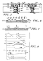
- Fig. 5 generally designated at 332 is a side view of the valve and pumping actuator illustrating position sensors of the infusion system having plural fluid input ports and at least one patient output port according to the present invention.
- the position sensors are operative to provide signal indications of the intended rotary position of the stepper motors.
- An annular sleeve 324 is mounted for rotation with the cams 280, 288 and stepper motor 296. As best seen in rolled out view in Fig. 7, the annular sleeve 324 has an open portion generally designated 328 and a closed portion generally designated 330. As shown in Figs.
- a dashed line 334 designates a first light path and a dashed line 336 designated a second light path through which the sleeve 324 rotates.
- the light paths 334, 336 may be provided by any suitable light emitting and light receiving devices such as infrared emitters and cooperative infrared detectors. As the sleeve 324 rotates it alternately transmits and occludes the light paths 334, 336 providing signal indications to be described of the rotary position of the stepper motor 296 to insure its intended rotary position.
- An annular sleeve 338 is mounted for rotation with the cam 314 and the stepper motor 316. As best seen in rolled out view in Fig. 8, the sleeve 338 has an open portion generally designated 342 and a closed portion generally designated 344. As shown in Figs. 6 and 7, a dashed line 346 designates a first light path and a dashed line 348 designates a second light path through which the sleeve 338 rotates. As the sleeve 338 rotates it alternately occludes and transmits the light paths 346, 348 providing signal indications to be described of the rotary position of the stepper motor 316 to insure its intended rotary position.
- FIG. 8 generally designated at 350 is a rolled out diagram illustrating the operation of the valve and pumping actuator and position sensors of the infusion system having plural fluid input ports and at least one patient output port according to the present invention.
- a line 352 illustrates the state of actuation of the "A" fluid input port (Fig. 1)
- a line 354 illustrates the state of actuation of the "B" fluid input port (Fig. 1)
- a line 356 illustrates the state of actuation of the "C” fluid input port (Fig. 1)
- a line 358 illustrates the state of actuation of the "D" fluid input port (Fig. 1).
- the states of actuation 352, 354, 356, 358 depend on the rotary position of the stepper motor 296 (Fig.
- a line 360 illustrates the state of actuation of the patient output port 26 (Fig. 1). The state of actuation of the output port depends on the rotary position of the stepper motor ((Fig. 4) that drives the cam 288 into contact with the roller 286 (Fig. 4) thereby displacing the plunger 268 out of contact with the cyclindrical valve projection.
- a line 366 illustrates a pumping sequence of the pumping plunger 272 (Fig.
- the sleeve 338 (Fig. 5) alternately occludes and transmits light along the light paths 346, 348 (Fig. 5) producing signal indications 368, 370 of the position of the stepper motor 316 (Fig. 5) to within one step accuracy of the start and end positions of the piston 242 (Fig. 4) during a pumping sequence.
- the signals 368, 370 are used by the system controller to insure proper orientation of the cam 314 (Fig. 4).
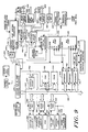
- FIG. 9 generally designated at 372 is a schematic diagram illustrating a preferred embodiment of the system controller of the infusion system having plural fluid input ports and at least one patient output port according to the present invention.
- the system controller 372 includes a first processor 374 and a second processor 376 slaved to the first processor 374.
- a bit serial asynchronous communication link 378 interconnects the processors 374, 376.
- the processor 374 controls operator input and output (I/O), and down loads instructions over the serial, communication link 378 into dual ping-pong buffers 379 for execution by the processor 376.
- the processor 376 controls in accordance with the instructions the state of actuation of the fluid input port valves and of the patient and vent output valves, controls the reciprocating motion of the pumping chamber piston at a rate and for a duration specified by the instructions, reads information representative of the pressure in the pressure chamber and writes information to the processor 374 representative of alarm situations and pressure data.
- the processor 374 is operative in response to the measured pressure data to adjust the reciprocating motion of the pumping piston to adapt desired to actual fluid flow rates.
- An address decoder 420 is connected to the address bus and to the interfaces 382, 392, 400, 408, 412, and 416 via a plurality of control lines 422.
- the address decoder 420 decodes the addresses appearing on the address bus and activates the corresponding control line to enable the addessed peripheral device for data reads and writes via the data bus 380.
- Battery and alarm LED's 424 described above in connection with the description of Fig. 3B are operatively connected to the processor 374.
- the data file 426 includes a block of selectively addressable RAM memory generally designated 428 for fluid input port "A”, a block of RAM memory generally designated 430 for fluid input port "B", a block of RAM memory generally designated 432 for fluid input port "C”, and a block of RAM memory generally designated 434 for fluid input port "D".
- Each block of RAM memory 426, 428, 430, and 432 at corresponding preselected address locations thereof specify an operator selected data structure for the corresponding fluid input port.
- the system I/O and pump control processor 374 selectively addresses the RAM 402 (Fig.
- the data structure for each line includes data representative of whether it is a primary or piggyback line.
- the data structure for primary lines includes data representative of infusion rate, infusion volume, infusion duration, and fluid container volume.
- the data structure for piggyback lines includes data representative of dilute line, dilute volume, and dilute rate for piggyback dilutions, and data representative of duration (Q) and repeat interval (X) for time sequential piggyback lines.
- the data structure for each line includes data representative of "prime” mode, "override” mode, and "normal-on” mode, and data representative of start time either after a selected delay or after infusion on a designated line.
- the data structure for each line includes data representative of syringe, and the preselected line for unsticking the syringe plunger.
- the data structure for each line includes data representative of flush and the selected flush line, flush volume, and flush rate.
- the data structure for each line further includes data representative of "call back”, and data representative of measured pressure including patient pressure, compliance pressure, and bottlehead pressure to be described.
- the data file 426 includes a block of selectably addressable RAM memory generally designated 436.
- the data structure of the block of RAM 436 for each line specifies data representative of the current history of the infusions already pumped on that line.
- the data file 426 includes a block of selectively addressable RAM memory generally designated 438 that specify global parameters for all the lines.
- the data structure of the block of RAM 438 specifies data representative of current time, maximum occlusion pressure, maximum infusion rate and volume, and KVO rate.
- the PROM 404 includes in preselected address locations thereof the code specifying the program for the system I/O and pump control processor 374.
- the PROM 404 also includes at preselected address locations thereof the display templates that prompt the system operator for both selecting a desired course of infusion and for selecting and controlling system operation described above in connection with the description of Fig. 3B.
- a data bus 426 is operatively connected to the pump control processor 376.
- RAM and PROM for the pump processor, not shown, are associated therewith in the usual manner.
- the pump control processor PROM contains the code specifying any one of possible pumping sequences to be described.
- Conventional latched drives 428 operatively connected to the data bus 426 are connected to a valve stepper motor 430.
- Conventional latched drives 432 operatively connected to the data bus 426 are connected to a pump stepper motor 434.
- An analog to digital converter (ADC) 436 operatively connected to the data bus 426 is connected to a pressure transducer 438 via a conventional analog signal conditioning module 440.
- ADC analog to digital converter
- Voltage inputs designated "V1-V6" are connected to the ADC 436 to monitor system power level as described above in connection with the description of Fig. 1.
- a plurality of control lines 442 are operatively connected to the pump control processor 376 for selecting the latched drives 428, for selecting the latched drives 432, and for selecting the analog to digital converter 436.
- a patient line solenoid 439 is connected to the latched drives 428, and a vent valve solenoid 441 is connected to the latched drives 432.
- Position sensors generally designated 444 operatively connected to the pump control processor 376 and the latched drives 428, 432 provide signal indications representative of the rotary position of the valve stepper motor 430 and of the rotary position of the pump stepper motor 434 described above in connection with the description of Figs. 6-9.
- the pump control processor is operative in the usual manner to enable selected ones of the devices 428, 432, and 436 by the corresponding control line, and to read and write at the appropriate times during a pumping sequence data thereto over the data bus 426.
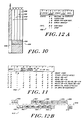
- FIG. 11 generally designated at 448 is a table illustrating an instruction byte produced by the system I/O and pump control processor 374 (Fig. 9) for controlling the pump control processor 376 (Fig. 9).
- the instruction byte includes eight bits designated 0 through 7.
- the one bit designated "ALL" of the bit field specifies that all data read by the pump processor is to be read by to the system I/O and pump control processor.
- the two bit designated "V1-V6" of the bit field specifies that the battery and regulator voltage data measured by the analog to digital converter is to be read by the system I/O and pump control processor.
- the three bit of the bit field designated "D0-D7 and C4" specifies either that the maximum occlusion pressure are to be written by the system I/O and pump processor to the pump processor or that the pressure and error data bytes "D0-D7" to be described are to be read by the system I/O and pump control processor from the pump processor.
- the four bit designated “norm and other" of the bit field specifies whether the system is to operate in the normal mode or not.
- the five bit designated “read/write” of the bit field specifies whether data is to be read by the pump control processor or whether data is to be written by the pump control processor.
- the six bit designated "X/Y" of the bit field specifies which of the ping-pong buffers is to be receive the next command.
- the seven bit designated "abort" of the bit field specifies whether an abort is to be effected by the pump control processor.
- the first instruction specifies whether the X or the Y buffer is to be aborted.
- the second instruction reads a status byte designated "S" to be described.
- the third instruction reads D0 through D7.
- the fourth instruction reads V0 to V6.
- the fifth instruction reads S, D0 through D7, V0 through V6, and C0 through C4 to be described.
- the sixth instruction writes C0 through C3 and reads D0 through D2.
- the seventh instruction writes C4, and reads D3.
- the eighth instruction instructs the pump processor to take a reference pressure measurement designated 0 PSI to be described.
- a "0, 1" specifies that the corresponding X or Y buffer is waiting to execute; a "1, 0" specifies that the corresponding instruction is being executed; a "1, 1" specifies that the corresponding buffer is ready for a new instruction; and a "0, 0” specifies an initialization state for the corresponding buffer.
- a "0, 0" specifies continuing the current control function and a "1, 1" specifies stopping the current function.
- et 452 is a timing diagram illustrating the communications protocol of the processors 374, 376 (Fig. 10).
- the boxes above the dashed line 454 illustrate the instructions written from the system I/O and pump control processor 374 to the pump control processor 376, and the boxes below the dashed line 454 illustrate the data read from the pump control processor by the system I/O and pump control processor 374.
- the pump control processor 374 sends over the transmission link 378 an instruction designated "I RD STAT" to read the status byte as illustrated at 456.
- the pump control processor 376 receives the instruction as illustrated at 458, and sends the status byte having the control bits "0, 0" back to the system I/O and pump control processor 374 as illustrated at 460.
- the system I/O and pump control processor receives the status byte as illustrated at 462, and sends it back to the pump control processor instructing it to continue as illustrated at 464.
- the process continues until the system I/O and pump control processor 374 instructs the pump control processor 376 to stop as illustrated by the box 466 having the control bits "1, 1".
- the pump control processor continues until it receives the instruction to stop as illustrated at 468 and sends it back to the system I/O and pump controller processor as illustrated by the box 470.
- the system I/O and pump control processor then sends an acknowledge instruction designated "ACK" to the pump control processor as illustrated by the box 472, which is received by the pump control processor 376 as illustrated by the box 474.
- ACK acknowledge instruction
- Fig. 13 generally designated at 476 is the C0 command byte; generally designated at 478 is the C1 command byte, generally designated at 480 is the C2 command byte, generally designated at 482 is the C3 command byte, and generally designated at 484 is the C4 command byte.
- the 0 through 6 bits of the bit field of the C0 byte 476 specify a number of microstrokes per pump stroke, and the seventh bit of the bit field specifies priming.
- the D0 data byte represents the bottle height pressure designated "P2" read by the pump processor and written in pump processor RAM during the pumping sequence.
- the bottle height pressure is the ADC reading of the pressure chamber when only an input valve is open normalized by the 0 PSI value.
- the D1 data byte is generally designated at 490.
- the D1 data byte represents the air-in-line compliance pressure designated "P4" read by the pump processor and written in pump processor RAM during the pumping sequence.
- the air-in-line compliance pressure as appears below is the difference of the ADC reading of the pressure chamber when the piston is successively driven partially in the pumping chamber and all valves are closed.
- the D2 byte is generally designated at 492.
- the D2 data byte represents volume correction designated "N1" and "N2" to be described read by the pump processor and written in pump processor RAM during the pumping sequence.
- the volume correction data as appears below depends on the pressure data and is employed to adapt actual to desired pumping rates.
- the D3 data byte is generally designated at 494.
- the D3 data byte represents the zero PSI pressure designated "P1" read by the pump processor and written in pump processor RAM during the pumping sequence.
- the 0 PSI pressure is the ADC reading of the pressure chamber when any input is just opened and the output valve is closed and the pumping piston is withdrawn prior to water hammer effects.
- the D4 data byte is generally designated at 496.
- the D4 data byte represents matching pressure designated "P3" to be described read by the pump processor and written in pump processor RAM during the pumping sequence.
- the D5 data byte is generally designated at 498.
- the D5 data byte represents the patient pressure designated "P5" read by the pump processor and written in pump processor RAM during the pumping sequence.
- the D6 and D7 bytes generally designated 500 and 502 have data therein representative of various error and alarm conditions that the pump controller monitors.
- the D6 and D7 data bytes are written during a pumping sequence in pump processor RAM.
- the D6 and D7 data bytes include data representing whether the stepper motors out are of proper rotary position, patient pressure greater than maximum occlusion pressure, air-in-line pressure less than minimum compliance pressure, empty bottle pressure, and cassette locking lever out of place.
- Fig. 15 generally designated at 504 is a data flow chart illustrating the operation of the infusion system having plural fluid input ports and at least one patient output port according to the present invention.
- the system I/O and pump control processor is operative to determine that a valid key, or combination of keys, has been entered. If a valid key or key combination has been entered, the processor is operative as shown by a block 508 to select the corresponding display template stored in PROM as shown by blocks 508, 510 and to display the selected template on the operator interactive display as shown by a block 512.
- the processor is operative to address for each data field the corresponding data locations in the data file 514 as illustrated by a block 516, and to write the operator selected data into the corresponding address locations of the data file for any selected one or more of the plural fluid input ports A, B, C, and D.
- the system I/O and pump control processor is operative to write the data into the RAM data file to provide RAM redundancy for preventing errors.
- the 0 through 6 bits of the bit field of the C0 command (Fig. 14) and the 13 through 15 bits of the bit field of the C1 command (Fig. 14) are specified by the data file.
- the system I/O and pump control processor is operative to read the data file address locations and the time as shown by a block 521 to determine if it should institute a pumping sequence on an active line.
- the processor is operative to determine whether the data file specifies operation in the priming mode as shown by a block 520.
- the processor is operative to produce instructions to stop all other pump functions as shown by the block 522, to produce instructions to prime the designated line as shown by a block 524, to produce instructions to inactivate all the fluid lines as shown by a block 526, and to return processing to the block 519.
- the processor is operative to produce instructions to stop all nonoverride functions as shown by a block 530, to produce instructions to pump the line designated at the specified rate as shown by a block 532, to inactive all fluid lines as shown by a block 534, and to return processing to the block 519.
- the processor is operative to produce instructions to suspend all nonflush functions as shown by a block 538, to produce instructions to flush the designated line as shown by a line 540, to reset the flush line as shown by a block 542, and to return processing to the block 519 as shown by a block 544.
- the processor is operative to determine whether the time for infusion is the present time or whether more delay is needed as shown by a block 548. If no more time is needed, the processor is operative to determine whether the data file designates the line as a primary line as shown by a block 550.
- the processor is operative to determine whether the data file specifies call back as shown by a block 552. If call back is specified, the processor is operative to sound an alarm and to pump in the KVO mode as shown by a block 554. If no call back is specified in the data file, the processor is operative to produce instructions to pump the specified line as shown by a block 556, and returns processing to the block 519 as shown by a block 558. If the line is a piggyback line, the processor is operative as shown by a block 551 to determine whether call back is specified in the data file. If call back is specified in the data file, the processor is operative to sound an alarm and to pump in the KVO mode as shown by a block 553.
- the processor is operative to determine if the data file specifies a syringe as shown by a block 555. If a syringe is specified, the processor is operative to produce instructions to stop all other functions and to unstick the syringe plunger as shown by a block 557. The processor is then operative to produce instructions to pump from the syringe at the selected rate as shown by a block 559, and to return processing to the block 519 as shown by a block 561. If syringe is not specified, the processor is operative to produce instructions to pump the designated line at the specified rate as shown by the block 556, and returns processing to the block 519 as shown by the block 558.
- the active line sequencer specifies the 7 bit of the bit field of the C0 command and the 5, 6, and 7 bits of the bit field of the C3 command.
- the processor is operative to calculate the number of strokes for the pumping plunger to effectuate the desired duration and rate of infusion.
- the processor is preferably operative to calculate the number of strokes per second according to the following relation: where Rate I is the specified infusion rate in milliliters per hour and VOL eff is the effective infused volume calculated as described below.
- Rate I is the specified infusion rate in milliliters per hour
- VOL eff is the effective infused volume calculated as described below.
- the tenths of second per stroke data is written in the 0 through 12 bits of the bit field of the C1 and C2 commands bytes.
- the processor is operative to buffer the instructions and commands described above in connection with the description of Figs. 12 and 14 in a command queue as shown by a block 566, which are written to the pump control processor as shown by a block 568 into a specified one of the X or Y buffers as illustrated by the blocks 570, 572.
- the pump control processor is operative to fetch the instructions from the appropriate buffer, and executes the specified pump control sequence as shown by a block 576 to controllably rotate the valve stepper motor to close and open the designated fluid input ports as illustrated by a block 578 and to controllably rotate the piston stepper motor to repetitively actuate the pumping piston as illustrated by a block 580.
- the pump control processor is operative during the pumping sequence to store in RAM the LED sensor signals from the valve stepper motor sleeve as illustrated by a block 582, and to store in RAM the LED sensor signals from the pump stepper motor sleeve as illustrated by a block 584.
- the pump processor is operative to read the analog to digital converter as shown by a block 586, to activate the vent output valve solenoid and the patient output line solenoid as shown by a block 589, and to write into pump control processor RAM the D0-D7 data as shown by a block 591 during the pumping sequence.
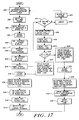
- Fig. 17 generally designated at 592 is a flow chart illustrating an exemplary pumping sequence of the pump control processor.
- the sequence 592 is preferably employed to controllably pump infusate at comparatively low operator selected rates of flow.
- the processor is operative to open the specified one of the fluid input port valves, to withdraw the pumping piston, and to write the A/D reading into the D3 RAM data location to measure 0 PSI.
- the processor is then operative to wait a predetermined time to allow fluid to flow from the selected input port into the pumping chamber as shown by a block 596.
- the processor is then operative to write the A/D reading normalized by the 0 PSI reading into the D0 data RAM location to measure the bottlehead pressure of the corresponding fluid container designated P2.
- the processor is then operative to close the valves as shown by a block 600 and to drive the pumping piston a selected distance, preferably four steps of the stepper motor, into the pumping chamber, and delays as shown by a block 602.
- the processor is then operative to write the A/D reading of the pressure transducer in RAM to take the matching pressure designated P3 as shown by a block 604.
- the processor is then operative to drive the pumping piston into the pumping chamber a further selected distance, preferably eight additional steps of the stepper motor, and delays as shown by a block 606.
- the processor is then operative to write the A/D reading of the pressure transducer designated P4 into RAM as shown by a block 608.
- the processor is then operative to compare the difference of the readings to determine whether air is in the line, to write the difference in the readings into the D1 RAM data location, and to either proceed or alarm in dependence on whether the change in pressure is below a minimum preselected reference compliance pressure.
- the processor is operative to abort the pumping sequence.
- the processor is then operative to vent air from the line using a pumping sequence to be described, to alarm as shown by a block 614 if air is in the line preferably for three consecutive measurements, and processing for each measurement is returned to the block 594.
- the processor is operative to withdraw the pumping piston out of the pumping chamber a preselected distance selected according to the measured pressures preferably calculated according to the relation 8(P4 - P5L)/(P4 - P3) steps of the stepper motor.
- the pressure P5L is the P5 pressure from the last stroke to be described. If P5L has yet to be measured in the pumping sequence, the processor assumes a specified value for the pressure P5L preferably equal to 0 PSI + 5.
- the processor is then operative to open the patient output line valve as shown by a block 618 and to write the A/D reading of the pressure transducer into RAM to measure the patient pressure designated P5 as shown by a block 620.
- the processor is then operative to determine whether the pressure P5 is less than the pressure P3. As shown by a block 624, if the pressure P5 is greater than the pressure P3, the processor is operative to successively drive the pumping piston step by step fully into the pumping chamber and to write the corresponding A/D reading into RAM. The processor is operative to compare the pressure reading for each step to the maximum occlusion value specified in the C4 command byte 484 (Fig. 14) to determine whether the patient line is occluded. If the line is occluded, the processor is operative to alarm if the pressure doesn't drop within a predetermined time interval, for example, 30 seconds.
- the processor is then operative to close the input and output valves as shown by a block 626.
- the processor is then operative to withdraw the pumping piston and write A/D reading into RAM.
- the processor then steps the pumping piston into the pumping chamber incrementally by steps of the stepper motor and writes the A/D reading into RAM.
- the processor is operative to repeat this process until the measured pressure equals the matching pressure P3 and stores that rotary position of the pumping piston stepper motor designated N2 in RAM where the measured pressure equals the pressure P3.
- the processor is then operative to drive the pumping piston fully into the pumping chamber and to open the patient output line valve as shown by a block 632.
- the processor is operative to successively drive the pumping piston almost fully into the pumping chamber, and to write the corresponding A/D reading into RAM.
- the processor is operative to compare the pressure reading for each step to the maximum occlusion value specified in the C4 command byte 484 (Fig. 14) to determine whether the patient line is occluded. If the line is occluded, the processor is operative to alarm if the pressure doesn't drop within a predetermined time interval, for example, 30 seconds. The processor is then operative to close the input and output valve as shown by a block 636.
- the processor is then operative to incrementally drive the pumping piston step by step into the pumping chamber and to write the corresponding A/D reading in RAM.
- the processor continues the process until the measured pressure is equal to the matching pressure P3 and stores the rotary position of the stepper motor at which the measured pressure equals the pressure P3 designated N1 in RAM.
- the processor is then operative to return the piston to the position of the stepper motor in the block 634, and to open the patient output line as shown by a block 642.
- the processor is then operative to drive the piston fully into the pumping chamber to pump the corresponding fluid into the patient output line as shown by a block 644.
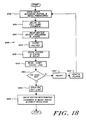
- Fig. 18 generally designated at 646 is a flow chart illustrating another exemplary pumping sequence of the pump control processor.
- the sequence 646 is preferably employed to pump infusate at comparatively higher operator selected rates of flow.
- the flow chart 646 is similar to the flow chart 592 (Fig. 18) except that the processor is operative to skip some of the patient pressure monitoring steps of the flow chart of Fig. 18 to allow for faster pumping rates.
- the particular pumping sequence is specified by the state of the 13, 14, and 15 bits of the bit field of the C1 command byte, and that the processor can be instructed to do several cycles of the pumping sequence illustrated in Fig. 19 followed by a sequence of the pumping sequence illustrated in Fig. 18 repetitively.
- the processor is operative to open a selected fluid input port valve, to withdraw the pumping piston, and to write the A/D reading of the pressure transducer into the D3 data byte.
- the processor is then operative to wait to allow the pumping chamber to fill with fluid from the selected fluid input port as shown by a block 650.
- the processor is then operative to write the A/D reading of the pressure transducer into the D0 data byte as shown by a block 652.
- the processor is then operative to close the fluid input and output port valves and then to drive the pumping piston a preselected distance into the pumping chamber, preferably twelve steps, and to delay as shown by a block 656.
- the processor is then operative to write the A/D reading of the pressure transducer into RAM to measure the compliance pressure for determining air in line as shown by a block 658.
- the processor is then operative to determine whether the compliance pressure minus the 0 PSI pressure is greater than the preselected maximum compliance pressure to determine whether there is air in line.
- the processor is operative to abort the current pumping sequence, to vent air from the line, to alarm as shown by a block 646 if air remains in the line preferably for three consecutive measurements, and processing for each measurement is returned to the block 648.
- the processor is operative to open the patient output line. The processor is then operative to drive the pumping piston into the pumping chamber and write the A/D reading into RAM. If the pressure is greater than the maximum occlusion pressure, the processor is operative to alarm as shown by a block 668.
- Fig. 19 generally designated at 670 is another pumping sequence of the pump control processor.
- the sequence 670 is preferably employed to vent air from the fluid flow path as described above in connection with the description of Figs. 18 and 19.
- the processor is operative to open the preselected fluid input port to be used for venting.
- the processor is then operative to withdraw the pumping piston out of the pumping chamber to allow the fluid to fill into the pumping chamber as shown by a block 674.
- the processor is then operative to open the vent valve as shown by a block 676 and to drive the pumping piston into the pumping chamber to clear air from the fluid path as shown by a block 678.
- the processor is then operative to close the vent valve. It will be appreciated that air may also be removed from the fluid flow path by the pressure of the gravity head without driving the piston into the pumping chamber.
- Fig. 20 generally designated at 684 is a flow chart illustrating another exemplary pumping sequence of the pump control processor.
- the sequence 684 is preferably employed to unstick the plunger of a syringe fluid input.
- the processor is operative to open the valve of the fluid port preselected as the unsticking fluid port and to withdraw the pumping piston to allow the unsticking fluid to flow into the pumping chamber as shown by a block 688.
- the processor is then operative to close the unsticking fluid valve as shown by a block 690 and to open the fluid input having the syringe as shown by a block 692.
- the processor is then operative to drive the pumping piston into the pumping chamber as shown by a block 694.
- the expelled fluid is thereby pumped through the cassette and into the syringe to unstick the plunger.
- the processor is then operative to close the syringe valve as shown by a block 696 and then to open the unsticking fluid valve as shown by a block 698.
- the processor is then operative to withdraw the pumping piston out of the pumping chamber to allow the unsticking fluid to flow into the pumping chamber as shown by a block 700.
- the processor is then operative to close the unsticking fluid valve as shown by a block 702 and to open the syringe valve as shown by a block 704.
- a block 710 is another exemplary pumping sequence of the pump control processor.
- the sequence 710 is preferably employed to abort a pumping sequence as described above in a connection with the description of Figs. 18 and 19.
- the processor is operative to close the fluid input and patient line output port valves and to open the vent valve as shown by a block 714.
- the processor then operative to drive the piston into the pumping chamber as shown by a block 716.
- the processor is then operative to close the vent valve as shown by a block 718 and to open the patient output line valve as shown by a block 720.
- the system I/O and pump control processor is then operative to read the status and data information compiled by the pump processor during the pumping sequences described above and write it back to the data file.
- the processor is then operative to strip off the D0 through D5 data bytes as shown by a block 724.
- the processor is operative to adapt the desired volume to the actual volume preferably according to the following relations,
- the processor is operative if the status information written into the data file indicates any of the several error and alarm conditions to select the corresponding display template as shown by a block 730, to display it on the operator display as shown by a block 732, and to generate the appropriate audible and visual alarms as shown by a block 734.
- the processor is operative to select the appropriate display template as shown by a block 730 and to display it on the operator interactive display as shown by the block 732.
- Fig. 22 generally designated at 626 is a diagram illustrating an exemplary operating sequence of the infusion system having plural fluid input ports and at least one patient output port according to the present invention.
- the sequencing diagram 626 illustrates pumping from the "B" fluid input port, and then pumping from the "D" fluid input port, utilizing the pumping sequence of Fig. 18, although it will be appreciated that any other valve order and pumping sequence is a variation of that specifically illustrated in Fig. 22.
- a line 738 illustrates the state of actuation of the "A" input valve
- a line 740 illustrates the state of actuation of the "B” fluid input port
- a line 742 illustrates the state of actuation of the "C” fluid input valve
- a line 744 illustrates the state of actuation of the "D” fluid input port value.
- a line 746 illustrates the state of actuation of the output valve designated “O” and a line 748 illustrates the rotary position of the pump plunger stepper motor during the exemplary sequence.
- a line 750 illustrates the reading of the pressure transducer.
- the pump processor is operative to rotate the valve stepper motor through the open position 752 of the "A” port and stops at the open position 754 of the "B" port.
- the processor is operative to take the A/D reading of the pressure transducer to measure the 0 PSI value as shown at 758.
- the processor is operative to take a reading from the analog to digital converter as shown at 760 to measure the bottle height pressure.
- the processor is then operative to close the"B" fluid input port as shown at 762.
Claims (43)
- Infusionssystem mit:
Mitteln (10, 20, 46, 48) zum Pumpen zu mindestens einer Auslaßleitung (26);
Mitteln (10, 12, 16, 18, 34, 48) zum Auswählen von einer oder mehreren zu pumpenden Flüssigkeitsquellen (16) in beliebiger Reihenfolge mittels der Mittel (46, 48) zum Pumpen und zum Auswählen von mindestens einem ersten Flüssigkeitseinlaß (140, 142) in einer ersten zeitlichen Reihenfolge, die eine gewünschte sukzessive zeitliche Reihenfolge festlegt und zum Auswählen von mindestens einem zweiten Flüssigkeitseinlaß (142), der sich von dem mindestens einen ersten Flüssigkeitseinlaß (140, 142) unterscheidet, für eine zweite zeitliche Ablauffolge, die ein gewünschtes Wiederholintervall und eine gewünschte Anzahl von Wiederholungen bezeichnet;
mit einem Taktgeber (394), der ein Zeitsignal erzeugt; und
mit an die Mittel (46, 48) zum Pumpen und an den Taktgeber (394) angeschlossenen Mitteln zur Steuerung der Mittel zum Pumpen (20, 46, 48) entsprechend einem Befehlssatz und dem Zeitsignal;
mit Mitteln für die Erstellung dieses Befehlssatzes (476, 484) für alle ausgewählten der einen oder mehreren Flüssigkeitsquellen (16) in beliebiger Reihenfolge, wodurch mindestens ein vom Benutzer auswählbarer Parameter von Parametern der Pumpförderrate des gesamten zu pumpenden Volumens und der Pumpdauer festgelegt wird,
dadurch gekennzeichnet,
daß die Mittel (10, 20, 46, 48) zum Pumpen zu der mindestens einen Auslaßleitung (26) und die Mittel zum Festlegen des Befehlssatzes (476, 482) so wirken, daß die ausgewählten Flüssigkeiten während der ersten und zweiten Zeitfolgen mit ausgewählten Förderraten gesteuert gepumpt werden, so daß ein Pumpen während der zweiten Zeitfolge ein Pumpen während der ersten Zeitfolge unterbricht für den Fall einer zeitlichen Koinzidenz zwischen diesen beiden Zeitfolgen;
daß ein System-I/O- und Steuerprozessor (374) so wirkt, daß er Datenplätze in einem Datenfeld (514) adressiert und von einer Bedienperson selektierte Daten in die Adressplätze einer Datei (514) für jeglichen ausgewählten der einen oder mehreren der Vielzahl von Einlässen (A, B, C, D) schreibt;
daß eine Ablaufsteuerung (518) für eine aktive Leitung bestimmt, von welchem Flüssigkeitseinlaß (16A-D) eine Flüssigkeit zu verabreichen ist;
und daß der System-I/O- und Steuerprozessor 374 durch die Ablaufsteuerung (518) für die aktive Leitung gesteuert wird, die Dateiadressplätze der Datei (514) zu lesen, um eine Pumpsequenz auf einer aktiven Leitung (556) einzurichten. - Infusionssystem nach Anspruch 1, dadurch gekennzeichnet, daß die Mittel (50, 52), die den Befehlssatz festlegen, zwei vom Benutzer auswählbare Parameter enthalten, die aus der Pumpförderrate, dem gesamten zu pumpenden Volumen und der Zeitdauer des Pumpens ausgewählt sind und daß sie eine vorbestimmte Kombination dieser Parameter für mindestens zwei der Vielzahl von Quellen enthalten.
- Infusionssystem nach Anspruch 1 oder 2, dadurch gekennzeichnet, daß der Befehlssatz einen Verdünnungs- und Mischbefehl (556) enthält, der die Mittel zum Pumpen so steuert, daß sie in einer der folgenden Betriebsarten pumpen, nämlich einer intermittierenden zeitlichen Ablauffolge oder einer zeitlichen Überlappung.
- Infusionssystem nach einem der Ansprüche 1 bis 3, dadurch gekennzeichnet, daß der Befehlssatz einen Rückrufbefehl (551, 552) enthält zur Steuerung der Mittel zum Pumpen, um die Bedienperson des Systems zu benachrichtigen, bevor ein Pumpen beginnt.
- Infusionssystem nach einem der Ansprüche 1 bis 4, dadurch gekennzeichnet, daß der Befehlssatz einen Aufrechterhaltungsbefehl (554) enthält, der die Mittel zum Pumpen anweist, eine Lösung zu pumpen, die so ausgewählt ist, daß die Vene des Patienten von einem auswählbaren Einlaß her offengehalten wird.
- Infusionssytem nach einem der Ansprüche 1 bis 5, dadurch gekennzeichnet, daß der Befehlssatz einen Primärbefehl (550) enthält, der die Mittel zum Pumpen anweist, in einer kontinuierlichen Betriebsart oder einer Zeitablauffolge-Betriebsart zu pumpen.
- Infusionssystem nach einem der Ansprüche 1 bis 6, dadurch gekennzeichnet, daß der Befehlssatz einen Rückrufbefehl (551) enthält, der die Mittel zum Pumpen so steuert, daß das Pumpen gestoppt wird, wenn eine incompatible Infusion auftritt und daß die Bedienperson des Systems rückgerufen wird.
- Infusionssystem nach einem der Ansprüche 1 bis 7, dadurch gekennzeichnet, daß der Befehlssatz einen Übersteuerungsbefehl (528) enthält, der die Mittel zum Pumpen so steuert, daß sie in einer Notsituation pumpen.
- Infusionssystem nach einem der Ansprüche 1 bis 8, dadurch gekennzeichnet, daß der Befehlssatz einen Spülbefehl (536) enthält, der die Mittel zum Pumpen so steuert, daß sie Flüssigkeit durch den mindestens einen Auslaß pumpen.
- Infusionssystem nach einem der Ansprüche 1 bis 9, dadurch gekennzeichnet, daß der Befehlssatz einen Vorbereitungs- oder Füllbefehl (520) aufweist, der die Mittel zum Pumpen steuert, Flüssigkeit durch den mindestens einen Auslaß hindurch zu pumpen.
- Infusionssystem nach einem der Ansprüche 1 bis 10, dadurch gekennzeichnet, daß der Befehlssatz einen Stoppbefehl enthält, um die Mittel zum Pumpen in steuerbarer Weise zu stoppen.
- Infusionssystem nach einem Ansprüche 1 bis 11, dadurch gekennzeichnet, daß der Befehlssatz einen Spritzenlösebefehl 557 enthält, zum Lösen des Kolbens einer Spritze, die an einer der Vielzahl von Flüssigkeitsquellen angeschlossen ist.
- Infusionssystem nach einem der Ansprüche 1 bis 12, dadurch gekennzeichnet, daß der Befehlssatz einen Befehl (180, 736) für die Infusionshistorie enthält, um den gegenwärtigen Status bzw. Zustand der Infusion zu liefern.
- Infusionssystem nach einem der Ansprüche 1 bis 13, dadurch gekennzeichnet, daß die Einrichtmittel ein interaktives Display (50, 126) für die Bedienperson und eine Vielzahl von Funktions- und Datentasten enthalten.
- Infusionssystem nach einem der Ansprüche 1 bis 14, dadurch gekennzeichnet, daß die Steuerungsmittel einen Pumpensteuerprozessor (376) aufweisen, der dem System-I/O- und Pumpensteuerprozessor (374) nachgeordnet ist.
- Infusionssystem nach einem der Ansprüche 1 bis 15, dadurch gekennzeichnet, daß der System-I/O- und Pumpensteuerprozessor den Befehlssatz erzeugt und zu dem Pumpensteuerprozessor lädt, für die Ausführung durch letzteren.
- Infusionssystem nach einem der Ansprüche 1 bis 16, dadurch gekennzeichnet, daß die Auswahlmittel eine Vielzahl von ventilgesteuerten (18, 206) Flüssigkeitseinlässen (16, 194), eine Vielzahl von Stößeln (266) zum Steuern des Betätigungszustandes eines entsprechenden der Ventile und Mittel (274, 276, 278, 280, 296) zum Betätigen der Stößel aufweisen.
- Infusionssystem nach Anspruch 17, dadurch gekennzeichnet, daß die Betätigungsmittel eine von einem Schrittmotor angetriebene Nockenscheibe (280) aufweisen, die so angeordnet ist, daß verhindert wird, daß gleichzeitig irgendein Einlaß und der Auslaß in einem "offenen" Zustand (280, 288) sind.
- Infusionssystem nach Anspruch 18, gekennzeichnet durch Mittel (324, 334, 336) zur Erzeugung einer Signalanzeige der Drehstellung des Schrittmotors (296).
- Infusionssystem nach einem der Ansprüche 1 bis 19, dadurch gekennzeichnet, daß die Mittel zum Pumpen (20, 46, 48) eine Pumpkammer (20, 208) enthalten, die von einem Kolben (272) betätigt wird, der steuerbar in die Pumpenkammer eingeführt oder aus ihr herausgezogen wird und Mittel (274, 312, 316) zum Steuern des Pumpenkolbens.
- Infusionssystem nach Anspruch 20, dadurch gekennzeichnet, daß die Steuerungsmittel für den Pumpenkolben eine von einem Schrittmotor angetriebene Nockenscheibe (314) aufweisen.
- Infusionssystem nach Anspruch 21, gekennzeichnet durch Mittel (338) zur Erzeugung einer Signalanzeige der Drehstellung des Schrittmotor.
- Infusionssystem nach einem der Ansprüche 1 bis 22, dadurch gekennzeichnet, daß der Befehlssatz einen Befehl für ein maximales Flüssigkeitsvolumen enthält, der den Maximalwert der Flüssigkeit bestimmt, die von allen der vielen Flüssigkeitsquellen während eines festgelegten Zeitintervalles verabreicht werden kann.
- Infusionssystem nach einem der Ansprüche 1 bis 23, dadurch gekennzeichnet, daß der Befehlssatz einen Befehl für eine maximale Flüssigkeitsförderrate enthält, die die maximale Förderrate festlegt, die von allen der Vielzahl von Flüssigkeitsquellen während eines festgelegten Zeitintervalles verabreicht werden kann.
- Infusionssystem nach Anspruch 24, gekennzeichnet durch Mittel (576, 578, 580) zum Auswählen von zwei Flüssigkeitseinlässen in einer dritten zeitlichen Reihenfolge, die eine Verdünnung festlegt.
- Infusionssystem nach Anspruch 24 oder 26, dadurch gekennzeichnet, daß die Auswahlmittel eine Kassette (12, 194-196) enthalten, die eine Vielzahl von Flüssigkeitseinlässen (194) und mindestens einen Flüssigkeitsauslaß (194) enthält, die längs eines gemeinsamen Flüssigkeitsströmungsweges (24, 228) angeschlossen sind und daß sie zusätzlich Mittel (40, 42, 44, 249, 260, 310) enthalten, die mit der Kassette zusammenwirken, um Daten zu liefern, die für mindestens einen der Drücke der Flüssigkeit an einem entsprechenden Flüssigkeitseinlaß, den Druck der Flüssigkeit in der Auslaßleitung und dem Druck der Flüssigkeit in der von den Einlässen und Auslässen getrennten Kassette entspricht.
- Infusionssystem nach Anspruch 26, gekennzeichnet durch Mittel (98, 436), die auf die genannten Druckdaten ansprechen und mit den Mitteln zum Pumpen gekoppelt sind, um die Pumprate an druckabhängige Durchflußänderungen anzupassen.
- Infusionssystem nach Anspruch 26 oder 27, gekennzeichnet durch Mittel (26, 28, 34, 114, 441), die an die Mittel zum Pumpen gekoppelt sind, um in Abhängigkeit von den Druckdaten Luft aus dem Flüssigkeitsströmungsweg zu entfernen.
- Infusionssystem nach einem der Ansprüche 26 bis 29, dadurch gekennzeichnet, daß die Auswahlmittel ein Ventil (230) aufweisen, das in einer entsprechenden der Vielzahl von Einlässen und dem Patientenauslaß angeordnet ist und daß weiterhin Mittel (34, 46, 280, 288, 296, 314, 316) vorgesehen sind, um die Ventile in ersten, zweiten und dritten zeitlichen Ablauffolgen anzusteuern.
- Infusionssystem nach Anspruch 29, dadurch gekennzeichnet, daß die Ablauffolgemittel eine Vielzahl von Prozessor gesteuerten (374, 376) Ventilbetätigungseinrichtungen (274, 428) enthalten.
- Infusionssystem nach einem der Ansprüche 24 bis 30, dadurch gekennzeichnet, daß die Mittel zum Pumpen eine Pumpenkammer (240) aufweisen, die in Strömungsverbindung (204) mit jedem der Vielzahl von Flüssigkeitseinlässen steht und Mittel (314, 316) zum Evakuieren der Pumpenkammer mit einer ausgewählten Förderrate.
- Infusionssystem nach Anspruch 31, dadurch gekennzeichnet, daß die Evakuierungsmittel einen Prozessor gesteuerten, hin und her verschieblichen Pumpenkammerkolben (272) aufweisen.
- Infusionssystem nach einem der Ansprüche 1 bis 32, dadurch gekennzeichnet, daß das System einen Flüssigkeitsverteiler (12, 194-196) mit mehreren Flüssigkeitseinlaßventilen (254) aufweist, von denen jedes mit einer zugeordneten der mehreren Flüssigkeitseinlässe verbunden ist, sowie ein Patientenauslaßventil (262), das mit dem Flüssigkeitsauslaß verbunden ist und mit der Vielzahl von Flüssigkeitseinlaßventilen in Strömungsverbindung (210) steht und daß das System Mittel (240, 256) enthält, die mit der Vielzahl von Flüssigkeitseinlaßventilen und dem Flüssigkeitsauslaßventil in Strömungsverbindung steht, um Flüssigkeit von irgendeinem Einlaß durch den Auslaß hindurch zu pumpen;
wobei die Steuerungsmittel eine Systemsteuerung (371, 376) mit einem Speicher (402, 404) aufweisen;
wobei die Mittel zum Einrichten eines Befehlssatzes folgendes aufweisen:
Mittel (384), die an die Systemsteuerung gekoppelt sind, um Daten in den ersten Speicher einzuschreiben, die für eine gewünschte Infusionsablauffolge repräsentativ sind, einschließlich mindestens einer zeitlichen Ablauffolge für zu verabreichende Flüssigkeit aus einem oder mehreren der Flüssigkeitseinlässe, einer Flüssigkeitsförderrate, die von einem entsprechenden von den einen oder mehreren Flüssigkeitseinlässen zu verabreichen ist und einer Zeitdauer für die Verabreichung von Flüssigkeit von einem der einen oder mehreren Flüssigkeitseinlässe;
wobei das System weiterhin aufweist:
einen Druckwandler (308), der an die Systemsteuerung und an den Flüssigkeitsverteiler angeschlossen ist, um zweite Daten (436, 440) zu liefern, die dem Druck in dem Flüssigkeitsverteiler entsprechen; und wobei die Auswahlmittel (10, 18, 34) enthalten:
Mittel (34, 266, 278, 280, 288, 314), die an die Systemsteuerung und den Flüssigkeitsverteiler angeschlossen sind und in Abhängigkeit von den ersten und zweiten Daten arbeiten, um selektiv individuelle Flüssigkeitseinlaßventile zu betätigen in Abhängigkeit von den ersten Daten, um zu ermöglichen, daß die ausgewählte Flüssigkeit in den Flüssigkeitsverteiler gelangt und um sowohl das Auslaßventil als auch die Mittel zum Pumpen selektiv zu betätigen, in Abhängigkeit von den ersten und zweiten Daten. - Infusionssystem nach Anspruch 33, dadurch gekennzeichnet, daß der Verteiler weiterhin einen Entlüftungsauslaß (114, 232) und ein zugeordnetes Ventil (232) aufweist, die in Verbindung mit der Vielzahl von Einlaßventilen und der Pumpenkammer stehen.
- Infusionssystem nach Anspruch 33 oder 34, dadurch gekennzeichnet, daß die Systemsteuerung selektiv betreibbar (80) ist, um Flüssigkeit von einem ausgewählten der Vielzahl von Flüssigkeitseinlässen durch den Verteiler hindurch und aus der Entlüftungsöffnung zu verabreichen, um den Verteiler von jeglicher Luft in ihm zu befreien bzw. die Luft auszuspülen, um eine Luftembolie zu verhindern.
- Infusionssystem nach Anspruch 35, dadurch gekennzeichnet, daß die Systemsteuerung bewirkt (80), daß Flüssigkeit von irgendeinem ausgewählten der Vielzahl von Flüssigkeitseinlässen durch den Verteiler hindurch und aus dem Entlüftungsauslaß heraus gepumpt wird.
- Infusionssystem nach Anspruch 35, dadurch gekennzeichnet, daß die Systemsteuerung bewirkt, daß ermöglicht wird, daß Flüssigkeit durch Schwerkraft aus einem ausgewählten der Vielzahl von Flüssigkeitseinlässen durch den Verteiler hindurch und aus dem Entlüftungsauslaß heraus fließt.
- Infusionssystem nach einem der Ansprüche 33 bis 37, dadurch gekennzeichnet, daß der Flüssigkeitsverteiler eine Kassette mit ersten und zweiten zueinander passenden Gehäuseabschnitten (194, 196) aufweist, wobei einer der Gehäuseabschnitte eine Pumpenkammer (214) bildet und wobei der Verteiler weiterhin eine flexible Membran (198) enthält, die dazwischen geschichtet ist und eine Pumpenmembran (256) oberhalb der Pumpenkammer bildet und eine Vielzahl von Ventildichtkegeln (254), die entsprechende der Flüssigkeitseinlaßventile sowie das Flüssigkeitsauslaßventil bilden.
- Infusionssystem nach Anspruch 38, dadurch gekennzeichnet, daß die Pumpenmembran domförmig ist.
- Infusionssystem nach einem der Ansprüche 34 bis 39, dadurch gekennzeichnet, daß die Systemsteuerung einen System-I/O- und Pumpensteuerprozessor (374) und einen Pumpenprozessor (376) aufweist, wobei letzterer über eine Kommunikationsverbindung (378) dem System-I/O- und Pumpensteuerprozessor nachgeordnet ist.
- Infusionssystem nach Anspruch 40, dadurch gekennzeichnet, daß die ersten Mittel ein interaktives Display (50, 388) für die Bedienperson und ein Tastenfeld (52, 384) für die Bedienperson aufweisen, wobei letzteres eine Vielzahl von Funktions- und Datentasten aufweisen, die mit dem System-I/O- und Pumpensteuerprozessor verbunden sind.
- Infusionssystem nach Anspruch 40, dadurch gekennzeichnet, daß der Drucksensor wirkungsmäßig mit dem Pumpensteuerprozessor verbunden ist und daß der Pumpensteuerprozessor so arbeitet, daß er Werte des Druckwandlers liest, um Daten zu erhalten, die dem Druck an mindestens einer der entsprechenden Flüssigkeitseinlässe entspricht sowie dem Druck in dem Flüssigkeitsauslaß und der Luft in dem Flüssigkeitsverteiler.
- Infusionssystem nach einem der Ansprüche 38 bis 42, dadurch gekennzeichnet, daß die Mittel eine Vielzahl von Stößeln oder Kolben (266) enthalten, die individuell für eine hin- und hergehende Bewegung angebracht sind, eine erste, von einem Schrittmotor angetriebene Nockenscheibe (280) zum Antreiben der Stößel bzw. Kolben gegen einen entsprechenden Einlaß- und Auslaßventilkegel bzw. von diesem fort und daß sie weiterhin einen Pumpenkolben (272) aufweisen, der für eine hin- und hergehende Bewegung an einer zweiten, von einem Schrittmotor angetriebenen Nockenscheibe (314) angebracht ist, um den Pumpenkolben steuerbar in die Pumpenkammer hinein zu bewegen oder aus ihr heraus.
Applications Claiming Priority (2)
| Application Number | Priority Date | Filing Date | Title |
|---|---|---|---|
| US57818084A | 1984-02-08 | 1984-02-08 | |
| US578180 | 1984-02-08 |
Related Child Applications (2)
| Application Number | Title | Priority Date | Filing Date |
|---|---|---|---|
| EP88104196.6 Division-Into | 1985-02-08 | ||
| EP88104197.4 Division-Into | 1985-02-08 |
Publications (2)
| Publication Number | Publication Date |
|---|---|
| EP0154191A1 EP0154191A1 (de) | 1985-09-11 |
| EP0154191B1 true EP0154191B1 (de) | 1994-05-18 |
Family
ID=24311769
Family Applications (3)
| Application Number | Title | Priority Date | Filing Date |
|---|---|---|---|
| EP88104197A Expired EP0288717B1 (de) | 1984-02-08 | 1985-02-08 | Druckempfindliches Infusionssystem |
| EP85101328A Expired - Lifetime EP0154191B1 (de) | 1984-02-08 | 1985-02-08 | Infusionssystem mit mehreren Fluid-Eingängen und mindestens einem Patienten-Ausgang |
| EP88104196A Expired EP0288716B1 (de) | 1984-02-08 | 1985-02-08 | Kassette für ein Infusionssystem |
Family Applications Before (1)
| Application Number | Title | Priority Date | Filing Date |
|---|---|---|---|
| EP88104197A Expired EP0288717B1 (de) | 1984-02-08 | 1985-02-08 | Druckempfindliches Infusionssystem |
Family Applications After (1)
| Application Number | Title | Priority Date | Filing Date |
|---|---|---|---|
| EP88104196A Expired EP0288716B1 (de) | 1984-02-08 | 1985-02-08 | Kassette für ein Infusionssystem |
Country Status (9)
| Country | Link |
|---|---|
| US (2) | US4696671A (de) |
| EP (3) | EP0288717B1 (de) |
| JP (2) | JPS60182961A (de) |
| AU (1) | AU592052B2 (de) |
| CA (1) | CA1257165A (de) |
| DE (3) | DE3586596T2 (de) |
| IE (1) | IE850309L (de) |
| IL (1) | IL74236A (de) |
| PT (1) | PT79940A (de) |
Families Citing this family (351)
| Publication number | Priority date | Publication date | Assignee | Title |
|---|---|---|---|---|
| US6241704B1 (en) | 1901-11-22 | 2001-06-05 | Sims Deltec, Inc. | Drug pump systems and methods |
| US5935099A (en) * | 1992-09-09 | 1999-08-10 | Sims Deltec, Inc. | Drug pump systems and methods |
| US4763282A (en) * | 1983-05-27 | 1988-08-09 | Larry Rosenberg | Programming format and apparatus for the improved coherent beam coupler system and method |
| US5108367A (en) * | 1984-02-08 | 1992-04-28 | Abbott Laboratories | Pressure responsive multiple input infusion system |
| US4705506A (en) * | 1984-11-29 | 1987-11-10 | Minnesota Mining And Manufacturing Company | Multiple solution IV system with setup error protection |
| US4840542A (en) * | 1985-03-27 | 1989-06-20 | Quest Medical, Inc. | Infusion pump with direct pressure sensing |
| US4753270A (en) * | 1985-10-01 | 1988-06-28 | Omni-Flow, Inc. | Cam actuator assembly for a programmable infusion system |
| US5088515A (en) * | 1989-05-01 | 1992-02-18 | Kamen Dean L | Valve system with removable fluid interface |
| US4842584A (en) * | 1987-05-01 | 1989-06-27 | Abbott Laboratories | Disposable fluid infusion pumping chamber cassette and drive mechanism thereof |
| US4950244A (en) * | 1987-05-01 | 1990-08-21 | Abbott Laboratories | Pressure sensor assembly for disposable pump cassette |
| US4925444A (en) * | 1987-08-07 | 1990-05-15 | Baxter Travenol Laboratories, Inc. | Closed multi-fluid delivery system and method |
| US5041086A (en) * | 1987-12-04 | 1991-08-20 | Pacesetter Infusion, Ltd. | Clinical configuration of multimode medication infusion system |
| CA1329946C (en) * | 1987-12-04 | 1994-05-31 | Paul A. Koenig | User interface for medication infusion system |
| US4919596A (en) * | 1987-12-04 | 1990-04-24 | Pacesetter Infusion, Ltd. | Fluid delivery control and monitoring apparatus for a medication infusion system |
| US4884013A (en) * | 1988-01-15 | 1989-11-28 | Sherwood Medical Company | Motor unit for a fluid pump and method of operation |
| US5011378A (en) * | 1988-07-08 | 1991-04-30 | I-Flow Corporation | Pump tube mount and cartridge for infusion pump |
| US4950245A (en) * | 1988-07-08 | 1990-08-21 | I-Flow Corporation | Multiple fluid cartridge and pump |
| US5131816A (en) * | 1988-07-08 | 1992-07-21 | I-Flow Corporation | Cartridge fed programmable ambulatory infusion pumps powered by DC electric motors |
| PL159857B1 (en) * | 1989-01-20 | 1993-01-29 | Method for the continuous control of the carried infusion microbatcher | |
| US5153827A (en) * | 1989-01-30 | 1992-10-06 | Omni-Flow, Inc. | An infusion management and pumping system having an alarm handling system |
| US5108373A (en) * | 1989-09-25 | 1992-04-28 | Baxter International Inc. | Intravenous metering device |
| US5190527A (en) * | 1989-09-25 | 1993-03-02 | Baxter International Inc. | Intravenous metering device |
| DE4004134A1 (de) * | 1990-02-10 | 1991-08-29 | Roland Wex | Vorrichtung zum zusammenfuehren mehrerer infusionen und/oder injektionen |
| US5127907A (en) * | 1990-12-06 | 1992-07-07 | Abbott Laboratories | System for eliminating or reducing static electricity in infusion pumping systems |
| US5486286A (en) * | 1991-04-19 | 1996-01-23 | Althin Medical, Inc. | Apparatus for performing a self-test of kidney dialysis membrane |
| US5192269A (en) * | 1991-07-24 | 1993-03-09 | Abbott Laboratories | Multi-valve manifold for drug infusion systems |
| US5171301A (en) * | 1991-10-15 | 1992-12-15 | Imed Corporation | Multiple mini-pump infusion system |
| DE4137837C1 (de) * | 1991-11-18 | 1992-10-29 | Fresenius Ag, 6380 Bad Homburg, De | |
| AU3415893A (en) * | 1991-12-20 | 1993-07-28 | Abbott Laboratories | Automated drug infusion system with autopriming |
| ES2049173B1 (es) * | 1992-07-14 | 1996-12-16 | Garcia Ernesto Jorge Morales | Manipulador de llaves de perfusion de tres vias. |
| CA2125693C (en) * | 1992-10-15 | 2005-05-03 | Alan D. Ford | An infusion pump with an electronically loadable drug library |
| US5252044A (en) * | 1992-10-20 | 1993-10-12 | Medflow, Inc. | Parenteral fluid pump with disposable cassette |
| GB2273533B (en) * | 1992-12-18 | 1996-09-25 | Minnesota Mining & Mfg | Pumping cassette with integral manifold |
| US5438510A (en) * | 1993-03-03 | 1995-08-01 | Deka Products Limited Partnership | User interface and monitoring functions for automated peritoneal dialysis systems |
| US5324422A (en) * | 1993-03-03 | 1994-06-28 | Baxter International Inc. | User interface for automated peritoneal dialysis systems |
| ATE170759T1 (de) * | 1993-03-03 | 1998-09-15 | Deka Products Lp | Vorrichtung zur peritonaldialyse mit einer zur luftabscheidung ausgerüsteten flüssigkeitsverteil- und pumpenkassette. |
| US5431626A (en) * | 1993-03-03 | 1995-07-11 | Deka Products Limited Partnership | Liquid pumping mechanisms for peritoneal dialysis systems employing fluid pressure |
| US5474683A (en) * | 1993-03-03 | 1995-12-12 | Deka Products Limited Partnership | Peritoneal dialysis systems and methods employing pneumatic pressure and temperature-corrected liquid volume measurements |
| US5350357A (en) * | 1993-03-03 | 1994-09-27 | Deka Products Limited Partnership | Peritoneal dialysis systems employing a liquid distribution and pumping cassette that emulates gravity flow |
| US5385540A (en) * | 1993-05-26 | 1995-01-31 | Quest Medical, Inc. | Cardioplegia delivery system |
| US5645531A (en) * | 1993-05-26 | 1997-07-08 | Quest Medical, Inc. | Constant pressure blood mixture delivery system and method |
| US5573502A (en) * | 1993-05-26 | 1996-11-12 | Quest Medical, Inc. | Display panel and controls for blood mixture delivery system |
| DE4320365C2 (de) * | 1993-06-19 | 2000-07-13 | Uvo Hoelscher | Mehrkanal-Dosiersystem |
| US5482438A (en) * | 1994-03-09 | 1996-01-09 | Anderson; Robert L. | Magnetic detent and position detector for fluid pump motor |
| US5658133A (en) * | 1994-03-09 | 1997-08-19 | Baxter International Inc. | Pump chamber back pressure dissipation apparatus and method |
| US5630710A (en) * | 1994-03-09 | 1997-05-20 | Baxter International Inc. | Ambulatory infusion pump |
| US5609575A (en) * | 1994-04-11 | 1997-03-11 | Graseby Medical Limited | Infusion pump and method with dose-rate calculation |
| US5603613A (en) * | 1994-09-12 | 1997-02-18 | Ivac Corp | Fluid delivery system having an air bubble ejector |
| US5568912A (en) * | 1994-09-12 | 1996-10-29 | Ivac Corporation | Sliding flow controller having channel with variable size groove |
| US5563347A (en) * | 1994-09-12 | 1996-10-08 | Ivac Corp | Pressure sensing vessel adapted to be preloaded against a sensor |
| US5575632A (en) * | 1994-09-12 | 1996-11-19 | Ivac Medical Systems, Inc. | Engineered pumping segment |
| US5601420A (en) * | 1994-09-12 | 1997-02-11 | Ivac Medical Systems, Inc. | Interlock, latching, and retaining mechanism for an infusion pump |
| US5673588A (en) * | 1995-01-26 | 1997-10-07 | Abbott Laboratories | Infusion pump retraction mechanism |
| US5628619A (en) * | 1995-03-06 | 1997-05-13 | Sabratek Corporation | Infusion pump having power-saving modes |
| US20030028145A1 (en) * | 1995-04-20 | 2003-02-06 | Duchon Douglas J. | Angiographic injector system with multiple processor redundancy |
| US7267666B1 (en) * | 1995-04-20 | 2007-09-11 | Acist Medical Systems, Inc. | Angiographic injector system with multiple processor redundancy |
| US8082018B2 (en) * | 1995-04-20 | 2011-12-20 | Acist Medical Systems, Inc. | System and method for multiple injection procedures on heart vessels |
| US5772635A (en) * | 1995-05-15 | 1998-06-30 | Alaris Medical Systems, Inc. | Automated infusion system with dose rate calculator |
| US5781442A (en) * | 1995-05-15 | 1998-07-14 | Alaris Medical Systems, Inc. | System and method for collecting data and managing patient care |
| US6671563B1 (en) | 1995-05-15 | 2003-12-30 | Alaris Medical Systems, Inc. | System and method for collecting data and managing patient care |
| KR19990043990A (ko) * | 1995-08-25 | 1999-06-25 | 앙드레 롤랜드 | 연속으로 작동되는 주입장치와 방법 |
| US5782805A (en) * | 1996-04-10 | 1998-07-21 | Meinzer; Randolph | Medical infusion pump |
| IL118766A0 (en) | 1996-07-01 | 1996-10-31 | Medun Ltd | Improved infusion apparatus |
| US6689091B2 (en) * | 1996-08-02 | 2004-02-10 | Tuan Bui | Medical apparatus with remote control |
| US5885245A (en) * | 1996-08-02 | 1999-03-23 | Sabratek Corporation | Medical apparatus with remote virtual input device |
| US5807336A (en) * | 1996-08-02 | 1998-09-15 | Sabratek Corporation | Apparatus for monitoring and/or controlling a medical device |
| US5895371A (en) * | 1996-08-27 | 1999-04-20 | Sabratek Corporation | Medical treatment apparatus and method |
| US6605057B2 (en) | 1996-10-24 | 2003-08-12 | Medtronic Ave, Inc. | Reinforced monorail balloon catheter |
| US5927349A (en) | 1996-12-09 | 1999-07-27 | Baxter International Inc. | Compounding assembly for nutritional fluids |
| US6070761A (en) * | 1997-08-22 | 2000-06-06 | Deka Products Limited Partnership | Vial loading method and apparatus for intelligent admixture and delivery of intravenous drugs |
| JP4291506B2 (ja) | 1997-08-22 | 2009-07-08 | デカ・プロダクツ・リミテッド・パートナーシップ | 静脈薬剤混合・射出用システム、方法及びカセット |
| US6199603B1 (en) | 1998-08-14 | 2001-03-13 | Baxter International Inc. | Compounding assembly for nutritional fluids |
| US6554798B1 (en) | 1998-08-18 | 2003-04-29 | Medtronic Minimed, Inc. | External infusion device with remote programming, bolus estimator and/or vibration alarm capabilities |
| US7901400B2 (en) | 1998-10-23 | 2011-03-08 | Covidien Ag | Method and system for controlling output of RF medical generator |
| US6164921A (en) | 1998-11-09 | 2000-12-26 | Moubayed; Ahmad Maher | Curvilinear peristaltic pump having insertable tubing assembly |
| US6398727B1 (en) | 1998-12-23 | 2002-06-04 | Baxter International Inc. | Method and apparatus for providing patient care |
| US6231560B1 (en) * | 1999-02-10 | 2001-05-15 | Baxter International Inc | Method and apparatus for automatically controlling the level of medication |
| US6471675B1 (en) * | 1999-04-30 | 2002-10-29 | Medtronic, Inc. | Passive flow control devices for implantable pumps |
| US6752787B1 (en) * | 1999-06-08 | 2004-06-22 | Medtronic Minimed, Inc., | Cost-sensitive application infusion device |
| US6875191B2 (en) | 1999-09-03 | 2005-04-05 | Baxter International Inc. | Blood processing systems and methods that alternate flow of blood component and additive solution through an in-line leukofilter |
| US6723062B1 (en) | 1999-09-03 | 2004-04-20 | Baxter International Inc. | Fluid pressure actuated blood pumping systems and methods with continuous inflow and pulsatile outflow conditions |
| US6949079B1 (en) | 1999-09-03 | 2005-09-27 | Baxter International Inc. | Programmable, fluid pressure actuated blood processing systems and methods |
| US6481980B1 (en) | 1999-09-03 | 2002-11-19 | Baxter International Inc. | Fluid flow cassette with pressure actuated pump and valve stations |
| US6759007B1 (en) | 1999-09-03 | 2004-07-06 | Baxter International Inc. | Blood processing systems and methods employing fluid pressure actuated pumps and valves |
| US7041076B1 (en) * | 1999-09-03 | 2006-05-09 | Baxter International Inc. | Blood separation systems and methods using a multiple function pump station to perform different on-line processing tasks |
| US6709412B2 (en) | 1999-09-03 | 2004-03-23 | Baxter International Inc. | Blood processing systems and methods that employ an in-line leukofilter mounted in a restraining fixture |
| DE19944343A1 (de) * | 1999-09-16 | 2001-04-12 | Fresenius Ag | Ventil |
| US6402741B1 (en) * | 1999-10-08 | 2002-06-11 | Sherwood Services Ag | Current and status monitor |
| US7933780B2 (en) * | 1999-10-22 | 2011-04-26 | Telaric, Llc | Method and apparatus for controlling an infusion pump or the like |
| US7645258B2 (en) | 1999-12-01 | 2010-01-12 | B. Braun Medical, Inc. | Patient medication IV delivery pump with wireless communication to a hospital information management system |
| US6497676B1 (en) | 2000-02-10 | 2002-12-24 | Baxter International | Method and apparatus for monitoring and controlling peritoneal dialysis therapy |
| US20030060765A1 (en) * | 2000-02-16 | 2003-03-27 | Arthur Campbell | Infusion device menu structure and method of using the same |
| US20010041869A1 (en) * | 2000-03-23 | 2001-11-15 | Causey James D. | Control tabs for infusion devices and methods of using the same |
| US6542902B2 (en) | 2000-03-24 | 2003-04-01 | Bridge Medical, Inc. | Method and apparatus for displaying medication information |
| US7131189B2 (en) | 2000-03-24 | 2006-11-07 | Cymbet Corporation | Continuous processing of thin-film batteries and like devices |
| DE10017953A1 (de) * | 2000-04-12 | 2001-10-25 | Europ Aesthetics Gmbh | Tumeszenzpumpe |
| US10353856B2 (en) | 2011-03-17 | 2019-07-16 | Carefusion 303, Inc. | Scalable communication system |
| US10062457B2 (en) | 2012-07-26 | 2018-08-28 | Carefusion 303, Inc. | Predictive notifications for adverse patient events |
| US7860583B2 (en) | 2004-08-25 | 2010-12-28 | Carefusion 303, Inc. | System and method for dynamically adjusting patient therapy |
| US9069887B2 (en) | 2000-05-18 | 2015-06-30 | Carefusion 303, Inc. | Patient-specific medication management system |
| US9427520B2 (en) | 2005-02-11 | 2016-08-30 | Carefusion 303, Inc. | Management of pending medication orders |
| US11087873B2 (en) | 2000-05-18 | 2021-08-10 | Carefusion 303, Inc. | Context-aware healthcare notification system |
| CA2409131C (en) | 2000-05-18 | 2015-12-15 | Alaris Medical Systems, Inc. | Distributed remote asset and medication management drug delivery system |
| US9741001B2 (en) | 2000-05-18 | 2017-08-22 | Carefusion 303, Inc. | Predictive medication safety |
| US20030069480A1 (en) * | 2001-04-28 | 2003-04-10 | Baxter International Inc. | A system and method for networking blood collection instruments within a blood collection facility |
| US6511457B2 (en) * | 2001-05-04 | 2003-01-28 | Garey Thompson | Airless syringe |
| US8034026B2 (en) | 2001-05-18 | 2011-10-11 | Deka Products Limited Partnership | Infusion pump assembly |
| MXPA03010576A (es) | 2001-05-18 | 2004-05-27 | Deka Products Lp | Equipo de infusion para una bomba de fluido. |
| US20030125662A1 (en) | 2002-01-03 | 2003-07-03 | Tuan Bui | Method and apparatus for providing medical treatment therapy based on calculated demand |
| US6985870B2 (en) | 2002-01-11 | 2006-01-10 | Baxter International Inc. | Medication delivery system |
| US8775196B2 (en) | 2002-01-29 | 2014-07-08 | Baxter International Inc. | System and method for notification and escalation of medical data |
| US10173008B2 (en) | 2002-01-29 | 2019-01-08 | Baxter International Inc. | System and method for communicating with a dialysis machine through a network |
| US8504179B2 (en) | 2002-02-28 | 2013-08-06 | Smiths Medical Asd, Inc. | Programmable medical infusion pump |
| US8250483B2 (en) | 2002-02-28 | 2012-08-21 | Smiths Medical Asd, Inc. | Programmable medical infusion pump displaying a banner |
| US8234128B2 (en) | 2002-04-30 | 2012-07-31 | Baxter International, Inc. | System and method for verifying medical device operational parameters |
| US20030222548A1 (en) * | 2002-05-31 | 2003-12-04 | Richardson William R. | Storage device for health care facility |
| AU2003265331B2 (en) | 2002-05-06 | 2008-03-20 | Covidien Ag | Blood detector for controlling anesu and method therefor |
| US6814547B2 (en) * | 2002-05-24 | 2004-11-09 | Baxter International Inc. | Medical fluid pump |
| US7153286B2 (en) | 2002-05-24 | 2006-12-26 | Baxter International Inc. | Automated dialysis system |
| US6764761B2 (en) | 2002-05-24 | 2004-07-20 | Baxter International Inc. | Membrane material for automated dialysis system |
| US7175606B2 (en) * | 2002-05-24 | 2007-02-13 | Baxter International Inc. | Disposable medical fluid unit having rigid frame |
| US20030217957A1 (en) * | 2002-05-24 | 2003-11-27 | Bowman Joseph H. | Heat seal interface for a disposable medical fluid unit |
| US7018361B2 (en) | 2002-06-14 | 2006-03-28 | Baxter International Inc. | Infusion pump |
| US6997905B2 (en) | 2002-06-14 | 2006-02-14 | Baxter International Inc. | Dual orientation display for a medical device |
| US7488309B2 (en) * | 2002-07-03 | 2009-02-10 | Bioanalytical Systems, Inc. | Device and method for drug delivery to animals |
| US7238164B2 (en) | 2002-07-19 | 2007-07-03 | Baxter International Inc. | Systems, methods and apparatuses for pumping cassette-based therapies |
| US7278983B2 (en) * | 2002-07-24 | 2007-10-09 | Medtronic Minimed, Inc. | Physiological monitoring device for controlling a medication infusion device |
| US20040068230A1 (en) * | 2002-07-24 | 2004-04-08 | Medtronic Minimed, Inc. | System for providing blood glucose measurements to an infusion device |
| US7527608B2 (en) | 2002-08-12 | 2009-05-05 | Lma North America, Inc. | Medication infusion and aspiration system and method |
| ATE390943T1 (de) * | 2002-10-16 | 2008-04-15 | Abbott Lab | Medizinische kassettenpumpe mit einzelnem kraftsensor zur bestimmung des beriebsstatus |
| US6846161B2 (en) * | 2002-10-24 | 2005-01-25 | Baxter International Inc. | Blood component processing systems and methods using fluid-actuated pumping elements that are integrity tested prior to use |
| US7097632B2 (en) * | 2002-10-28 | 2006-08-29 | Sherwood Services Ag | Automatic valve |
| US20060129092A1 (en) * | 2002-10-28 | 2006-06-15 | Sherwood Services Ag | Single lumen adapter for automatic valve |
| US7044948B2 (en) | 2002-12-10 | 2006-05-16 | Sherwood Services Ag | Circuit for controlling arc energy from an electrosurgical generator |
| US7835927B2 (en) * | 2002-12-27 | 2010-11-16 | Carefusion 303, Inc. | Medication management system |
| US7294209B2 (en) | 2003-01-02 | 2007-11-13 | Cymbet Corporation | Apparatus and method for depositing material onto a substrate using a roll-to-roll mask |
| US6906436B2 (en) | 2003-01-02 | 2005-06-14 | Cymbet Corporation | Solid state activity-activated battery device and method |
| US7603144B2 (en) | 2003-01-02 | 2009-10-13 | Cymbet Corporation | Active wireless tagging system on peel and stick substrate |
| US20040193325A1 (en) * | 2003-03-25 | 2004-09-30 | David Bonderud | Method and apparatus to prevent medication error in a networked infusion system |
| US7530968B2 (en) | 2003-04-23 | 2009-05-12 | Valeritas, Inc. | Hydraulically actuated pump for long duration medicament administration |
| EP1617776B1 (de) | 2003-05-01 | 2015-09-02 | Covidien AG | System zur programmierung und kontrolle eines elektrochirurgischen generatorsystems |
| US7367358B2 (en) * | 2005-02-02 | 2008-05-06 | Universal Infusion Technology, Llc | Medical fluid delivery system and method relating to the same |
| WO2005025646A2 (en) | 2003-09-08 | 2005-03-24 | U.S. Government As Represented By The Secretary Of The Army | System and method for providing servo-controlled resuscitation |
| NL1024370C2 (nl) * | 2003-09-24 | 2005-04-05 | Fornix Medical Systems Holding | Inrichting en werkwijze voor het afgeven van vloeistof, in het bijzonder voor medische toepassing. |
| US20060100907A1 (en) * | 2003-10-07 | 2006-05-11 | Holland Geoffrey N | Medication management system |
| US7490021B2 (en) * | 2003-10-07 | 2009-02-10 | Hospira, Inc. | Method for adjusting pump screen brightness |
| US20060089854A1 (en) * | 2003-10-07 | 2006-04-27 | Holland Geoffrey N | Medication management system |
| US7895053B2 (en) * | 2003-10-07 | 2011-02-22 | Hospira, Inc. | Medication management system |
| US20060089855A1 (en) * | 2003-10-07 | 2006-04-27 | Holland Geoffrey N | Medication management system |
| US20050278194A1 (en) * | 2003-10-07 | 2005-12-15 | Holland Geoffrey N | Medication management system |
| US9123077B2 (en) * | 2003-10-07 | 2015-09-01 | Hospira, Inc. | Medication management system |
| US8065161B2 (en) | 2003-11-13 | 2011-11-22 | Hospira, Inc. | System for maintaining drug information and communicating with medication delivery devices |
| US7211351B2 (en) | 2003-10-16 | 2007-05-01 | Cymbet Corporation | Lithium/air batteries with LiPON as separator and protective barrier and method |
| EP1675499B1 (de) | 2003-10-23 | 2011-10-19 | Covidien AG | Redundante temperaturüberwachung für elektrochirurgische systeme zur sicherheitserhöhung |
| US8104956B2 (en) | 2003-10-23 | 2012-01-31 | Covidien Ag | Thermocouple measurement circuit |
| US20050245899A1 (en) * | 2003-10-28 | 2005-11-03 | Swisher David R | Dual purpose adapter |
| US7662139B2 (en) | 2003-10-30 | 2010-02-16 | Deka Products Limited Partnership | Pump cassette with spiking assembly |
| US8158102B2 (en) | 2003-10-30 | 2012-04-17 | Deka Products Limited Partnership | System, device, and method for mixing a substance with a liquid |
| US7396336B2 (en) | 2003-10-30 | 2008-07-08 | Sherwood Services Ag | Switched resonant ultrasonic power amplifier system |
| US7896572B2 (en) * | 2003-10-30 | 2011-03-01 | Hospira, Inc. | Medical device system |
| US7632080B2 (en) | 2003-10-30 | 2009-12-15 | Deka Products Limited Partnership | Bezel assembly for pneumatic control |
| US7776006B2 (en) * | 2003-11-05 | 2010-08-17 | Baxter International Inc. | Medical fluid pumping system having real time volume determination |
| US8029454B2 (en) | 2003-11-05 | 2011-10-04 | Baxter International Inc. | High convection home hemodialysis/hemofiltration and sorbent system |
| US7092796B2 (en) | 2003-11-14 | 2006-08-15 | Cardinal Health 303, Inc. | System and method for verifying connection of correct fluid supply to an infusion pump |
| US7131860B2 (en) | 2003-11-20 | 2006-11-07 | Sherwood Services Ag | Connector systems for electrosurgical generator |
| CA2548557C (en) | 2003-12-05 | 2016-06-28 | Cardinal Health 303, Inc. | System and method for network monitoring of multiple medical devices |
| US7206715B2 (en) * | 2003-12-31 | 2007-04-17 | Cardinal Health 303, Inc. | Empty container detection using container side pressure sensing |
| US8672875B2 (en) * | 2003-12-31 | 2014-03-18 | Carefusion 303, Inc. | Medication safety enhancement for secondary infusion |
| US7255683B2 (en) * | 2003-12-31 | 2007-08-14 | Cardinal Health 303, Inc. | System for detecting the status of a vent associated with a fluid supply upstream of an infusion pump |
| WO2005067645A2 (en) | 2004-01-06 | 2005-07-28 | Cymbet Corporation | Layered barrier structure having one or more definable layers and method |
| US7766905B2 (en) | 2004-02-12 | 2010-08-03 | Covidien Ag | Method and system for continuity testing of medical electrodes |
| US8954336B2 (en) | 2004-02-23 | 2015-02-10 | Smiths Medical Asd, Inc. | Server for medical device |
| US7780662B2 (en) | 2004-03-02 | 2010-08-24 | Covidien Ag | Vessel sealing system using capacitive RF dielectric heating |
| US8313308B2 (en) * | 2004-03-26 | 2012-11-20 | Hospira, Inc. | Medical infusion pump with closed loop stroke feedback system and method |
| US7905710B2 (en) * | 2004-03-26 | 2011-03-15 | Hospira, Inc. | System and method for improved low flow medical pump delivery |
| ITMO20040085A1 (it) * | 2004-04-20 | 2004-07-20 | Gambro Lundia Ab | Dispositivo di infusione per fluidi medicali. |
| US7092797B2 (en) | 2004-05-25 | 2006-08-15 | Sherwood Services Ag | Flow monitoring system for a flow control apparatus |
| US8961461B2 (en) | 2004-05-27 | 2015-02-24 | Baxter International Inc. | Multi-state alarm system for a medical pump |
| US7927313B2 (en) | 2004-05-27 | 2011-04-19 | Baxter International Inc. | Medical device configuration based on recognition of identification information |
| WO2006014425A1 (en) | 2004-07-02 | 2006-02-09 | Biovalve Technologies, Inc. | Methods and devices for delivering glp-1 and uses thereof |
| DE102004047195B4 (de) * | 2004-09-29 | 2014-11-13 | Dräger Medical GmbH | Vorrichtung und Verfahren zur Dosierung von Medikamenten |
| EP1848471A4 (de) | 2005-02-02 | 2011-07-20 | Universal Infusion Technology Llc | System zur abgabe eines medizinischen fluids und darauf bezogenes verfahren |
| US20060206356A1 (en) * | 2005-03-09 | 2006-09-14 | Vanderveen Timothy W | Line verification for multi-pump arrays |
| CA2615479A1 (en) | 2005-07-15 | 2007-01-25 | Cymbet Corporation | Thin-film batteries with polymer and lipon electrolyte layers and methods |
| US7776478B2 (en) | 2005-07-15 | 2010-08-17 | Cymbet Corporation | Thin-film batteries with polymer and LiPON electrolyte layers and method |
| US20080077074A1 (en) * | 2006-08-15 | 2008-03-27 | Richard Keenan | Method of analyzing the composition of bodily fluids |
| US8734438B2 (en) | 2005-10-21 | 2014-05-27 | Covidien Ag | Circuit and method for reducing stored energy in an electrosurgical generator |
| US7947039B2 (en) | 2005-12-12 | 2011-05-24 | Covidien Ag | Laparoscopic apparatus for performing electrosurgical procedures |
| US9492606B2 (en) | 2006-02-09 | 2016-11-15 | Deka Products Limited Partnership | Apparatus, system and methods for an infusion pump assembly |
| WO2007092624A2 (en) | 2006-02-09 | 2007-08-16 | Deka Products Limited Partnership | Peripheral systems |
| US11478623B2 (en) | 2006-02-09 | 2022-10-25 | Deka Products Limited Partnership | Infusion pump assembly |
| US11497846B2 (en) | 2006-02-09 | 2022-11-15 | Deka Products Limited Partnership | Patch-sized fluid delivery systems and methods |
| US11364335B2 (en) | 2006-02-09 | 2022-06-21 | Deka Products Limited Partnership | Apparatus, system and method for fluid delivery |
| US10010669B2 (en) | 2006-02-09 | 2018-07-03 | Deka Products Limited Partnership | Systems and methods for fluid delivery |
| US11027058B2 (en) | 2006-02-09 | 2021-06-08 | Deka Products Limited Partnership | Infusion pump assembly |
| US7651493B2 (en) | 2006-03-03 | 2010-01-26 | Covidien Ag | System and method for controlling electrosurgical snares |
| US20070299398A1 (en) * | 2006-03-16 | 2007-12-27 | Seattle Medical Technologies | Infusion device capable of providing multiple liquid medicaments |
| AU2007233231B2 (en) | 2006-03-30 | 2011-02-24 | Mannkind Corporation | Multi-cartridge fluid delivery device |
| US8977517B2 (en) * | 2006-06-05 | 2015-03-10 | Creighton University | System and methods for evaluating efficacy of appetite-affecting drugs |
| WO2007143992A1 (en) * | 2006-06-12 | 2007-12-21 | Danfoss A/S | A pump |
| US8149131B2 (en) | 2006-08-03 | 2012-04-03 | Smiths Medical Asd, Inc. | Interface for medical infusion pump |
| US8858526B2 (en) | 2006-08-03 | 2014-10-14 | Smiths Medical Asd, Inc. | Interface for medical infusion pump |
| US8435206B2 (en) | 2006-08-03 | 2013-05-07 | Smiths Medical Asd, Inc. | Interface for medical infusion pump |
| US8965707B2 (en) | 2006-08-03 | 2015-02-24 | Smiths Medical Asd, Inc. | Interface for medical infusion pump |
| JP2008097281A (ja) * | 2006-10-11 | 2008-04-24 | Canon Inc | プログラム生成システム、シーケンスプログラム、シーケンス制御方法、およびシーケンサ装置 |
| EP2092470A2 (de) | 2006-10-16 | 2009-08-26 | Hospira, Inc. | System und verfahren für den vergleich und die verwendung von aktivitätsinformationen und konfigurationsinformationen aus verwaltungssystemen mit mehreren geräten |
| US20080119822A1 (en) * | 2006-11-17 | 2008-05-22 | Tyco Healthcare Group Lp | Enteral fluid delivery system and method for opeating the same |
| US8558964B2 (en) | 2007-02-15 | 2013-10-15 | Baxter International Inc. | Dialysis system having display with electromagnetic compliance (“EMC”) seal |
| US7998115B2 (en) | 2007-02-15 | 2011-08-16 | Baxter International Inc. | Dialysis system having optical flowrate detection |
| US7731689B2 (en) | 2007-02-15 | 2010-06-08 | Baxter International Inc. | Dialysis system having inductive heating |
| US8361023B2 (en) | 2007-02-15 | 2013-01-29 | Baxter International Inc. | Dialysis system with efficient battery back-up |
| US8870812B2 (en) | 2007-02-15 | 2014-10-28 | Baxter International Inc. | Dialysis system having video display with ambient light adjustment |
| CN101687077B (zh) * | 2007-02-26 | 2013-05-08 | 康尔福盛303有限公司 | 自动中继泵系统 |
| US8231578B2 (en) * | 2007-02-28 | 2012-07-31 | Hospira, Inc. | System and method for sequencing channels in a multi-channel infusion pump |
| US7857803B1 (en) | 2007-03-19 | 2010-12-28 | The United States Of America As Represented By The Secretary Of The Army | Burn patient resuscitation system and method |
| US7901376B2 (en) * | 2007-07-05 | 2011-03-08 | Baxter International Inc. | Dialysis cassette having multiple outlet valve |
| US8057437B2 (en) * | 2007-08-31 | 2011-11-15 | Hospira, Inc. | Radially sealing vavle for an infusion set |
| US8114276B2 (en) | 2007-10-24 | 2012-02-14 | Baxter International Inc. | Personal hemodialysis system |
| US7815605B2 (en) * | 2007-11-28 | 2010-10-19 | Souter Steve R | Emergency medication pump injection system |
| WO2009076429A2 (en) | 2007-12-10 | 2009-06-18 | Medrad, Inc. | Continuous fluid delivery system and method |
| US8517990B2 (en) | 2007-12-18 | 2013-08-27 | Hospira, Inc. | User interface improvements for medical devices |
| US10188787B2 (en) | 2007-12-31 | 2019-01-29 | Deka Products Limited Partnership | Apparatus, system and method for fluid delivery |
| CN114796703A (zh) | 2007-12-31 | 2022-07-29 | 德卡产品有限公司 | 输注泵组件 |
| US8881774B2 (en) | 2007-12-31 | 2014-11-11 | Deka Research & Development Corp. | Apparatus, system and method for fluid delivery |
| US8900188B2 (en) | 2007-12-31 | 2014-12-02 | Deka Products Limited Partnership | Split ring resonator antenna adapted for use in wirelessly controlled medical device |
| US9456955B2 (en) | 2007-12-31 | 2016-10-04 | Deka Products Limited Partnership | Apparatus, system and method for fluid delivery |
| US10080704B2 (en) | 2007-12-31 | 2018-09-25 | Deka Products Limited Partnership | Apparatus, system and method for fluid delivery |
| US8414563B2 (en) | 2007-12-31 | 2013-04-09 | Deka Products Limited Partnership | Pump assembly with switch |
| US8986253B2 (en) | 2008-01-25 | 2015-03-24 | Tandem Diabetes Care, Inc. | Two chamber pumps and related methods |
| WO2009111528A2 (en) * | 2008-03-05 | 2009-09-11 | Robert Hoch | Pressure sensing catheter |
| US8133197B2 (en) | 2008-05-02 | 2012-03-13 | Smiths Medical Asd, Inc. | Display for pump |
| US8062513B2 (en) | 2008-07-09 | 2011-11-22 | Baxter International Inc. | Dialysis system and machine having therapy prescription recall |
| US9514283B2 (en) | 2008-07-09 | 2016-12-06 | Baxter International Inc. | Dialysis system having inventory management including online dextrose mixing |
| US8057679B2 (en) | 2008-07-09 | 2011-11-15 | Baxter International Inc. | Dialysis system having trending and alert generation |
| US10089443B2 (en) | 2012-05-15 | 2018-10-02 | Baxter International Inc. | Home medical device systems and methods for therapy prescription and tracking, servicing and inventory |
| US20100040490A1 (en) * | 2008-08-12 | 2010-02-18 | Anis Rahman | Volumetric Infusion Pump and Method |
| US8408421B2 (en) | 2008-09-16 | 2013-04-02 | Tandem Diabetes Care, Inc. | Flow regulating stopcocks and related methods |
| WO2010033878A2 (en) | 2008-09-19 | 2010-03-25 | David Brown | Solute concentration measurement device and related methods |
| US8016789B2 (en) | 2008-10-10 | 2011-09-13 | Deka Products Limited Partnership | Pump assembly with a removable cover assembly |
| US8267892B2 (en) | 2008-10-10 | 2012-09-18 | Deka Products Limited Partnership | Multi-language / multi-processor infusion pump assembly |
| US8708376B2 (en) | 2008-10-10 | 2014-04-29 | Deka Products Limited Partnership | Medium connector |
| US8223028B2 (en) | 2008-10-10 | 2012-07-17 | Deka Products Limited Partnership | Occlusion detection system and method |
| US9180245B2 (en) | 2008-10-10 | 2015-11-10 | Deka Products Limited Partnership | System and method for administering an infusible fluid |
| US8262616B2 (en) | 2008-10-10 | 2012-09-11 | Deka Products Limited Partnership | Infusion pump assembly |
| US8066672B2 (en) | 2008-10-10 | 2011-11-29 | Deka Products Limited Partnership | Infusion pump assembly with a backup power supply |
| US8554579B2 (en) | 2008-10-13 | 2013-10-08 | Fht, Inc. | Management, reporting and benchmarking of medication preparation |
| US8105269B2 (en) | 2008-10-24 | 2012-01-31 | Baxter International Inc. | In situ tubing measurements for infusion pumps |
| DE102009012633A1 (de) | 2009-03-10 | 2010-09-23 | Fresenius Medical Care Deutschland Gmbh | Vorrichtung zum Verbinden einer externen Funktionseinrichtung mit einer Anordnung, Anordnung aufweisend eine solche Vorrichtung und Verfahren zum Verbinden |
| US8137083B2 (en) | 2009-03-11 | 2012-03-20 | Baxter International Inc. | Infusion pump actuators, system and method for controlling medical fluid flowrate |
| US8315885B2 (en) | 2009-04-14 | 2012-11-20 | Baxter International Inc. | Therapy management development platform |
| US8271106B2 (en) | 2009-04-17 | 2012-09-18 | Hospira, Inc. | System and method for configuring a rule set for medical event management and responses |
| WO2011014525A2 (en) | 2009-07-29 | 2011-02-03 | Icu Medical, Inc. | Fluid transfer devices and methods of use |
| AU2010278894B2 (en) | 2009-07-30 | 2014-01-30 | Tandem Diabetes Care, Inc. | Infusion pump system with disposable cartridge having pressure venting and pressure feedback |
| US8771251B2 (en) * | 2009-12-17 | 2014-07-08 | Hospira, Inc. | Systems and methods for managing and delivering patient therapy through electronic drug delivery systems |
| US8382447B2 (en) | 2009-12-31 | 2013-02-26 | Baxter International, Inc. | Shuttle pump with controlled geometry |
| CA2787178C (en) | 2010-01-22 | 2019-02-12 | Deka Products Limited Partnership | Method and system for shape-memory alloy wire control |
| US11244745B2 (en) | 2010-01-22 | 2022-02-08 | Deka Products Limited Partnership | Computer-implemented method, system, and apparatus for electronic patient care |
| US11881307B2 (en) | 2012-05-24 | 2024-01-23 | Deka Products Limited Partnership | System, method, and apparatus for electronic patient care |
| US20110313789A1 (en) | 2010-01-22 | 2011-12-22 | Deka Products Limited Partnership | Electronic patient monitoring system |
| US10911515B2 (en) | 2012-05-24 | 2021-02-02 | Deka Products Limited Partnership | System, method, and apparatus for electronic patient care |
| US11210611B2 (en) | 2011-12-21 | 2021-12-28 | Deka Products Limited Partnership | System, method, and apparatus for electronic patient care |
| US10242159B2 (en) | 2010-01-22 | 2019-03-26 | Deka Products Limited Partnership | System and apparatus for electronic patient care |
| US10453157B2 (en) | 2010-01-22 | 2019-10-22 | Deka Products Limited Partnership | System, method, and apparatus for electronic patient care |
| US11164672B2 (en) | 2010-01-22 | 2021-11-02 | Deka Products Limited Partnership | System and apparatus for electronic patient care |
| US8894631B2 (en) * | 2010-03-24 | 2014-11-25 | Baxter International Inc. | Multiple drug infusion system and method |
| US8567235B2 (en) | 2010-06-29 | 2013-10-29 | Baxter International Inc. | Tube measurement technique using linear actuator and pressure sensor |
| US8777590B2 (en) | 2010-12-22 | 2014-07-15 | Hospira, Inc. | Fluid delivery device identification and loading system |
| CA2839443A1 (en) * | 2011-06-20 | 2012-12-27 | Renaudia Medical, Llc | Distributed medication delivery system and method having autonomous delivery devices |
| US10556063B2 (en) * | 2011-06-20 | 2020-02-11 | Renaudia Medical, Llc | Distributed medication delivery using autonomous delivery device |
| US9853325B2 (en) | 2011-06-29 | 2017-12-26 | Space Charge, LLC | Rugged, gel-free, lithium-free, high energy density solid-state electrochemical energy storage devices |
| US10601074B2 (en) | 2011-06-29 | 2020-03-24 | Space Charge, LLC | Rugged, gel-free, lithium-free, high energy density solid-state electrochemical energy storage devices |
| US11527774B2 (en) | 2011-06-29 | 2022-12-13 | Space Charge, LLC | Electrochemical energy storage devices |
| US10658705B2 (en) | 2018-03-07 | 2020-05-19 | Space Charge, LLC | Thin-film solid-state energy storage devices |
| EP2745204A4 (de) | 2011-08-19 | 2015-01-07 | Hospira Inc | Systeme und verfahren für eine grafische schnittstelle mit einer grapfischen darstellung medizinischer daten |
| CN103930159B (zh) | 2011-09-13 | 2017-08-01 | 奎斯特医疗公司 | 心肌停搏液设备及方法 |
| EP2769357B1 (de) | 2011-10-21 | 2023-08-30 | ICU Medical, Inc. | Aktualisierungssystem für eine medizinische vorrichtung |
| WO2013090709A1 (en) | 2011-12-16 | 2013-06-20 | Hospira, Inc. | System for monitoring and delivering medication to a patient and method of using the same to minimize the risks associated with automated therapy |
| AU2012324021A1 (en) | 2011-12-22 | 2013-07-11 | Icu Medical, Inc. | Fluid transfer devices and methods of use |
| WO2013134519A2 (en) | 2012-03-07 | 2013-09-12 | Deka Products Limited Partnership | Apparatus, system and method for fluid delivery |
| JP5985848B2 (ja) * | 2012-03-22 | 2016-09-06 | テルモ株式会社 | 医療用ポンプ及びその制御方法 |
| CA2868801C (en) | 2012-03-30 | 2021-07-13 | Hospira, Inc. | Air detection system and method for detecting air in a pump of an infusion system |
| US9180242B2 (en) | 2012-05-17 | 2015-11-10 | Tandem Diabetes Care, Inc. | Methods and devices for multiple fluid transfer |
| US9555186B2 (en) | 2012-06-05 | 2017-01-31 | Tandem Diabetes Care, Inc. | Infusion pump system with disposable cartridge having pressure venting and pressure feedback |
| US9238100B2 (en) | 2012-06-07 | 2016-01-19 | Tandem Diabetes Care, Inc. | Device and method for training users of ambulatory medical devices |
| CA3089257C (en) | 2012-07-31 | 2023-07-25 | Icu Medical, Inc. | Patient care system for critical medications |
| NZ723391A (en) | 2012-08-31 | 2018-01-26 | Baxter Corp Englewood | Medication requisition fulfillment system and method |
| AU2013335277B2 (en) | 2012-10-26 | 2015-07-16 | Baxter Corporation Englewood | Improved image acquisition for medical dose preparation system |
| CA2889352C (en) | 2012-10-26 | 2021-12-07 | Baxter Corporation Englewood | Improved work station for medical dose preparation system |
| EP2948204B1 (de) | 2013-01-28 | 2021-08-25 | Smiths Medical ASD, Inc. | Medizinische sicherheitsvorrichtungen und verfahren |
| US11182728B2 (en) | 2013-01-30 | 2021-11-23 | Carefusion 303, Inc. | Medication workflow management |
| US10430554B2 (en) | 2013-05-23 | 2019-10-01 | Carefusion 303, Inc. | Medication preparation queue |
| US9641432B2 (en) | 2013-03-06 | 2017-05-02 | Icu Medical, Inc. | Medical device communication method |
| JP6660288B2 (ja) | 2013-03-13 | 2020-03-11 | ケアフュージョン 303、インコーポレイテッド | 患者固有投薬管理システム |
| WO2014164565A1 (en) | 2013-03-13 | 2014-10-09 | Carefusion 303, Inc. | Predictive medication safety |
| US9173998B2 (en) | 2013-03-14 | 2015-11-03 | Tandem Diabetes Care, Inc. | System and method for detecting occlusions in an infusion pump |
| US9421329B2 (en) | 2013-03-15 | 2016-08-23 | Tandem Diabetes Care, Inc. | Infusion device occlusion detection system |
| US10046112B2 (en) | 2013-05-24 | 2018-08-14 | Icu Medical, Inc. | Multi-sensor infusion system for detecting air or an occlusion in the infusion system |
| EP3003441B1 (de) | 2013-05-29 | 2020-12-02 | ICU Medical, Inc. | Infusionssystem mit einem oder mehreren sensoren und zusatzinformationen zur durchführung einer luftuntersuchung mit dem infusionssystem |
| ES2845748T3 (es) | 2013-05-29 | 2021-07-27 | Icu Medical Inc | Sistema de infusión y método de uso que impiden la sobresaturación de un convertidor analógico-digital |
| WO2015003145A1 (en) | 2013-07-03 | 2015-01-08 | Deka Products Limited Partnership | Apparatus, system and method for fluid delivery |
| AU2014312122A1 (en) | 2013-08-30 | 2016-04-07 | Icu Medical, Inc. | System and method of monitoring and managing a remote infusion regimen |
| US9662436B2 (en) | 2013-09-20 | 2017-05-30 | Icu Medical, Inc. | Fail-safe drug infusion therapy system |
| US20150133861A1 (en) | 2013-11-11 | 2015-05-14 | Kevin P. McLennan | Thermal management system and method for medical devices |
| US10311972B2 (en) | 2013-11-11 | 2019-06-04 | Icu Medical, Inc. | Medical device system performance index |
| CA2930830C (en) | 2013-11-19 | 2019-12-03 | Hospira, Inc. | Infusion pump automation system and method |
| CA2931195C (en) | 2013-11-25 | 2019-09-24 | Icu Medical, Inc. | Methods and systems for filling iv bags with therapeutic fluid |
| ES2776363T3 (es) | 2014-02-28 | 2020-07-30 | Icu Medical Inc | Sistema de infusión y método que utiliza detección óptica de aire en línea de doble longitud de onda |
| AU2015253001A1 (en) | 2014-04-30 | 2016-10-20 | Icu Medical, Inc. | Patient care system with conditional alarm forwarding |
| WO2015184366A1 (en) | 2014-05-29 | 2015-12-03 | Hospira, Inc. | Infusion system and pump with configurable closed loop delivery rate catch-up |
| US9724470B2 (en) | 2014-06-16 | 2017-08-08 | Icu Medical, Inc. | System for monitoring and delivering medication to a patient and method of using the same to minimize the risks associated with automated therapy |
| SG11201610717WA (en) | 2014-06-30 | 2017-01-27 | Baxter Corp Englewood | Managed medical information exchange |
| US10143795B2 (en) | 2014-08-18 | 2018-12-04 | Icu Medical, Inc. | Intravenous pole integrated power, control, and communication system and method for an infusion pump |
| US9539383B2 (en) | 2014-09-15 | 2017-01-10 | Hospira, Inc. | System and method that matches delayed infusion auto-programs with manually entered infusion programs and analyzes differences therein |
| US11575673B2 (en) | 2014-09-30 | 2023-02-07 | Baxter Corporation Englewood | Central user management in a distributed healthcare information management system |
| US11107574B2 (en) | 2014-09-30 | 2021-08-31 | Baxter Corporation Englewood | Management of medication preparation with formulary management |
| AU2015358483A1 (en) | 2014-12-05 | 2017-06-15 | Baxter Corporation Englewood | Dose preparation data analytics |
| US11344668B2 (en) | 2014-12-19 | 2022-05-31 | Icu Medical, Inc. | Infusion system with concurrent TPN/insulin infusion |
| CN113069635B (zh) | 2015-01-09 | 2023-06-23 | 拜耳医药保健有限公司 | 具有多次使用可丢弃套件的多流体递送系统及其特征 |
| US10850024B2 (en) | 2015-03-02 | 2020-12-01 | Icu Medical, Inc. | Infusion system, device, and method having advanced infusion features |
| US11948112B2 (en) | 2015-03-03 | 2024-04-02 | Baxter Corporation Engelwood | Pharmacy workflow management with integrated alerts |
| US10549248B2 (en) | 2015-04-23 | 2020-02-04 | B. Braun Medical Inc. | Compounding device system, software and method for controlling the process of compounding admixtures |
| ES2845725T3 (es) | 2015-05-26 | 2021-07-27 | Icu Medical Inc | Sistema y método de bomba de infusión con capacidad de fuente de editor de múltiples bibliotecas de fármacos |
| NZ737340A (en) | 2015-05-26 | 2019-06-28 | Icu Medical Inc | Disposable infusion fluid delivery device for programmable large volume drug delivery |
| CN116206744A (zh) | 2015-06-25 | 2023-06-02 | 甘布罗伦迪亚股份公司 | 具有分布式数据库的医疗装置系统和方法 |
| NZ741377A (en) | 2015-10-09 | 2022-02-25 | Deka Products Lp | Fluid pumping and bioreactor system |
| WO2017096072A1 (en) | 2015-12-04 | 2017-06-08 | Icu Medical, Inc. | Systems methods and components for transferring medical fluids |
| CA3023658C (en) | 2016-05-13 | 2023-03-07 | Icu Medical, Inc. | Infusion pump system and method with common line auto flush |
| EP3468635A4 (de) | 2016-06-10 | 2019-11-20 | ICU Medical, Inc. | Akustischer durchflusssensor für kontinuierliche medikamentenflussmessungen und feedback-steuerung von infusionen |
| AU2017295722B2 (en) | 2016-07-14 | 2022-08-11 | Icu Medical, Inc. | Multi-communication path selection and security system for a medical device |
| USD851745S1 (en) | 2016-07-19 | 2019-06-18 | Icu Medical, Inc. | Medical fluid transfer system |
| CA3031529A1 (en) | 2016-07-25 | 2018-02-01 | Icu Medical, Inc. | Systems, methods, and components for trapping air bubbles in medical fluid transfer modules and systems |
| US11299705B2 (en) | 2016-11-07 | 2022-04-12 | Deka Products Limited Partnership | System and method for creating tissue |
| JP7153017B2 (ja) | 2016-12-21 | 2022-10-13 | ガンブロ・ルンディア・エービー | 外部ドメインをサポートするセキュアクラスタドメインを有する情報技術インフラストラクチャを含む医療機器システム |
| US11179516B2 (en) | 2017-06-22 | 2021-11-23 | Baxter International Inc. | Systems and methods for incorporating patient pressure into medical fluid delivery |
| US10089055B1 (en) | 2017-12-27 | 2018-10-02 | Icu Medical, Inc. | Synchronized display of screen content on networked devices |
| CN108245738A (zh) * | 2018-01-16 | 2018-07-06 | 湖北民族学院 | 一种智能静脉输液电子安全警报系统 |
| DE102018104229B3 (de) | 2018-02-26 | 2019-05-16 | Torsten Van Venrooy | Infusionspumpe |
| WO2019209963A1 (en) | 2018-04-24 | 2019-10-31 | Deka Products Limited Partnership | Apparatus and system for fluid delivery |
| US10861592B2 (en) | 2018-07-17 | 2020-12-08 | Icu Medical, Inc. | Reducing infusion pump network congestion by staggering updates |
| EP3824386B1 (de) | 2018-07-17 | 2024-02-21 | ICU Medical, Inc. | Aktualisierung von infusionspumpenmedikamentenbibliotheken und betriebssoftware in einer vernetzten umgebung |
| US11152108B2 (en) | 2018-07-17 | 2021-10-19 | Icu Medical, Inc. | Passing authentication token to authorize access to rest calls via web sockets |
| AU2019306492A1 (en) | 2018-07-17 | 2021-02-11 | Icu Medical, Inc. | Systems and methods for facilitating clinical messaging in a network environment |
| US10692595B2 (en) | 2018-07-26 | 2020-06-23 | Icu Medical, Inc. | Drug library dynamic version management |
| WO2020023231A1 (en) | 2018-07-26 | 2020-01-30 | Icu Medical, Inc. | Drug library management system |
| USD939079S1 (en) | 2019-08-22 | 2021-12-21 | Icu Medical, Inc. | Infusion pump |
| US11278671B2 (en) | 2019-12-04 | 2022-03-22 | Icu Medical, Inc. | Infusion pump with safety sequence keypad |
| CN114867507A (zh) * | 2019-12-23 | 2022-08-05 | 阿西斯特医药系统公司 | 模块化流体输送系统 |
| DE102020104665A1 (de) * | 2020-02-21 | 2021-08-26 | B. Braun Melsungen Aktiengesellschaft | Sicherheitsrelevante Anwendung |
| US11590057B2 (en) | 2020-04-03 | 2023-02-28 | Icu Medical, Inc. | Systems, methods, and components for transferring medical fluids |
| AU2021311443A1 (en) | 2020-07-21 | 2023-03-09 | Icu Medical, Inc. | Fluid transfer devices and methods of use |
| US11135360B1 (en) | 2020-12-07 | 2021-10-05 | Icu Medical, Inc. | Concurrent infusion with common line auto flush |
Family Cites Families (75)
| Publication number | Priority date | Publication date | Assignee | Title |
|---|---|---|---|---|
| US1853811A (en) * | 1930-09-03 | 1932-04-12 | William R Hewitt | Electromagnetic fuel pump |
| US2672051A (en) * | 1951-10-29 | 1954-03-16 | Cutter Lab | Valved flow meter for parenteral solution injection sets |
| US2767277A (en) * | 1952-12-04 | 1956-10-16 | James F Wirth | Control system for power operated fluid pumps |
| US2907325A (en) * | 1953-11-27 | 1959-10-06 | R K Laros Company | Venoclysis equipment |
| US2880909A (en) * | 1956-02-07 | 1959-04-07 | Tokheim Corp | Automatic circuit control device |
| NL248506A (de) * | 1958-07-11 | |||
| GB1114247A (en) * | 1964-06-01 | 1968-05-22 | Holger Hesse | Infusion apparatus |
| US3559644A (en) * | 1967-12-14 | 1971-02-02 | Robert F Shaw | Liquid infusion apparatus |
| CH508877A (fr) * | 1968-04-02 | 1971-06-15 | Micromedic Systems Inc | Doseur pour liquide |
| US3620650A (en) * | 1969-12-05 | 1971-11-16 | Robert F Shaw | Gas-disabled liquid-pumping apparatus |
| US3749285A (en) * | 1971-09-13 | 1973-07-31 | Haemonetics Corp | Programmed liquid delivery system |
| US3874826A (en) * | 1973-02-05 | 1975-04-01 | Ingemar H Lundquist | Intravenous delivery pump |
| US3798982A (en) * | 1973-04-25 | 1974-03-26 | Origo | Pump actuator including rotatable cams |
| CH582518A5 (de) * | 1973-08-30 | 1976-12-15 | Sandoz Ag | |
| US3901231A (en) * | 1974-02-07 | 1975-08-26 | Baxter Laboratories Inc | Infusion pump apparatus |
| US3884228A (en) * | 1974-02-26 | 1975-05-20 | Lynkeus Corp | Intravenous feeding system |
| US3923060A (en) * | 1974-04-23 | 1975-12-02 | Jr Everett H Ellinwood | Apparatus and method for implanted self-powered medication dispensing having timing and evaluator means |
| US4056333A (en) * | 1974-07-15 | 1977-11-01 | Valleylab | Intravenous feeding pump failure alarm system |
| US3941126A (en) * | 1974-08-08 | 1976-03-02 | Dietrich Joseph W | Apparatus for long term intravenous administration of diluted incompatible multiple medications |
| US4037598A (en) * | 1974-08-12 | 1977-07-26 | Ivac Corporation | Method and apparatus for fluid flow control |
| US3982534A (en) * | 1975-01-10 | 1976-09-28 | Buckman Thomas P | Intravenous administration system |
| DE2513467C3 (de) * | 1975-03-26 | 1979-10-31 | Siemens Ag, 1000 Berlin Und 8000 Muenchen | Gerät zur Infusion von Flüssigkeiten in den menschlichen oder tierischen Körper |
| US4126132A (en) * | 1975-07-28 | 1978-11-21 | Andros Incorporated | Intravenous and intra arterial delivery system |
| US4030495A (en) * | 1975-11-07 | 1977-06-21 | Baxter Travenol Laboratories, Inc. | Twin check valve pump system having fail-safe characteristic |
| US4086653A (en) * | 1976-01-09 | 1978-04-25 | Thermo Electron Corporation | Pneumatic pump monitor |
| US4142523A (en) * | 1976-03-31 | 1979-03-06 | Koninklijke Emballage Industrie Van Leer B.V. | Flow control device for the intravenous administration of liquids |
| CA1110137A (en) * | 1976-05-24 | 1981-10-06 | Ingemar H. Lundquist | Intravenous liquid pumping system and method |
| US4094318A (en) * | 1976-07-09 | 1978-06-13 | Burron Medical Products, Inc. | Electronic control means for a plurality of intravenous infusion sets |
| US4094319A (en) * | 1976-11-01 | 1978-06-13 | Joa Curt G | Sanitary pad with multiple end folds |
| US4273122A (en) * | 1976-11-12 | 1981-06-16 | Whitney Douglass G | Self contained powered injection system |
| DE2652026C2 (de) * | 1976-11-15 | 1983-01-05 | Siemens AG, 1000 Berlin und 8000 München | Gerät zur Infusion von Flüssigkeiten |
| US4191184A (en) * | 1977-01-06 | 1980-03-04 | Carlisle Jeffrey A | Intravenous infusion regulation system with reciprocal metering means |
| US4191183A (en) * | 1977-10-31 | 1980-03-04 | Barry Mendelson | Mixing chamber for use in plural medical liquid intravenous administration set |
| US4210138A (en) * | 1977-12-02 | 1980-07-01 | Baxter Travenol Laboratories, Inc. | Metering apparatus for a fluid infusion system with flow control station |
| DE2758467C2 (de) * | 1977-12-28 | 1985-04-04 | Siemens AG, 1000 Berlin und 8000 München | Vorrichtung zur vorprogrammierbaren Infusion von Flüssigkeiten |
| DE2758368C2 (de) * | 1977-12-28 | 1985-10-17 | Siemens AG, 1000 Berlin und 8000 München | Vorrichtung zur vorprogrammierbaren Infusion von Flüssigkeiten |
| US4207871A (en) * | 1978-06-07 | 1980-06-17 | Imed Corporation | System for controlling the flow of intravenous fluids to a patient |
| US4204538A (en) * | 1978-06-07 | 1980-05-27 | Imed Corporation | Cassette for intravenous controller |
| DE2826033C2 (de) * | 1978-06-14 | 1982-04-15 | Messerschmitt-Bölkow-Blohm GmbH, 8000 München | Infusionspumpe |
| US4261356A (en) * | 1978-10-23 | 1981-04-14 | Baxter Travenol Laboratories, Inc. | Method and apparatus for controlling the dispensing of fluid |
| US4308866A (en) * | 1978-11-02 | 1982-01-05 | University Of Southern California | Infusion controlling apparatus and method |
| US4236522A (en) * | 1978-11-06 | 1980-12-02 | Medtronic, Inc. | Asynchronous/demand made programmable digital cardiac pacemaker |
| DE2855713C2 (de) * | 1978-12-22 | 1983-09-22 | Manfred Dr.med. 2000 Hamburg Doehn | Vorrichtung zur Infusion von Lösungen aus mehreren Infusionsflaschen |
| US4324238A (en) * | 1979-02-28 | 1982-04-13 | Abbott Laboratories | Equipment sets having a combined air barrier and liquid sequencing device for the sequential administration of medical liquids at dual flow rates |
| US4316460A (en) * | 1979-02-28 | 1982-02-23 | Abbott Laboratories | Gravitational flow system for the sequential administration of medical liquids |
| US4236880A (en) * | 1979-03-09 | 1980-12-02 | Archibald Development Labs, Inc. | Nonpulsating IV pump and disposable pump chamber |
| US4265240A (en) * | 1979-04-16 | 1981-05-05 | Imed Corporation | Apparatus for providing a controlled introduction of intravenous fluid to a patient |
| US4373527B1 (en) * | 1979-04-27 | 1995-06-27 | Univ Johns Hopkins | Implantable programmable medication infusion system |
| US4731051A (en) * | 1979-04-27 | 1988-03-15 | The Johns Hopkins University | Programmable control means for providing safe and controlled medication infusion |
| US4280494A (en) * | 1979-06-26 | 1981-07-28 | Cosgrove Robert J Jun | System for automatic feedback-controlled administration of drugs |
| US4303376A (en) * | 1979-07-09 | 1981-12-01 | Baxter Travenol Laboratories, Inc. | Flow metering cassette and controller |
| DE3018641C2 (de) * | 1980-05-16 | 1986-05-28 | Hans 8228 Freilassing Rodler | Automatische Infusionspumpe |
| AU546785B2 (en) * | 1980-07-23 | 1985-09-19 | Commonwealth Of Australia, The | Open-loop controlled infusion of diabetics |
| US4336800A (en) * | 1980-08-01 | 1982-06-29 | Oximetrix, Inc. | Intravenous metering device |
| US4394862A (en) * | 1980-08-25 | 1983-07-26 | Baxter Travenol Laboratories, Inc. | Metering apparatus with downline pressure monitoring system |
| US4460353A (en) * | 1980-09-08 | 1984-07-17 | Imed Corporation | Drop controller |
| DE3035670A1 (de) * | 1980-09-22 | 1982-04-29 | Siemens AG, 1000 Berlin und 8000 München | Vorrichtung zur infusion von fluessigkeiten in den menschlichen oder tierischen koerper |
| US4648406A (en) * | 1981-02-02 | 1987-03-10 | Michael Ebert | Physiological pressure measuring system |
| US4391598A (en) * | 1981-04-28 | 1983-07-05 | Quest Medical, Inc. | Intravenous drug additive delivery system with electronic control |
| US4411651A (en) * | 1981-05-26 | 1983-10-25 | Pacesetter Systems, Inc. | Device and method useful in monitoring fluid flow in a drug injector |
| US4392849A (en) * | 1981-07-27 | 1983-07-12 | The Cleveland Clinic Foundation | Infusion pump controller |
| JPS5869522A (ja) * | 1981-10-22 | 1983-04-25 | オリンパス光学工業株式会社 | 内視鏡装置 |
| US4447191A (en) * | 1981-12-15 | 1984-05-08 | Baxter Travenol Laboratories, Inc. | Control circuit for a blood fractionation apparatus |
| DE3209721A1 (de) * | 1982-03-17 | 1983-09-29 | MGVG Medizinische Geräte Vertriebs-Gesellschaft mbH, 8000 München | Infusionsgeraet |
| US4432754A (en) * | 1982-05-24 | 1984-02-21 | Alza Corporation | Apparatus for parenteral infusion of fluid containing beneficial agent |
| US4460355A (en) * | 1982-06-11 | 1984-07-17 | Ivac Corporation | Fluid pressure monitoring system |
| US4513796A (en) * | 1982-06-24 | 1985-04-30 | Baxter Travenol Laboratories, Inc. | High speed bulk compounder |
| US4464170A (en) * | 1982-09-29 | 1984-08-07 | Miles Laboratories, Inc. | Blood glucose control apparatus and method |
| EP0107150B2 (de) * | 1982-10-18 | 1992-04-15 | Siemens Aktiengesellschaft | Vorrichtung zur Abgabe von Medikamenten |
| US4624661A (en) * | 1982-11-16 | 1986-11-25 | Surgidev Corp. | Drug dispensing system |
| US4553958A (en) * | 1983-02-04 | 1985-11-19 | Quest Medical, Inc. | IV Delivery controller |
| US4561443A (en) * | 1983-03-08 | 1985-12-31 | The Johns Hopkins University | Coherent inductive communications link for biomedical applications |
| US4563173A (en) * | 1983-04-19 | 1986-01-07 | National Biomedical Research Foundation | Pump-actuated sequencing valve and system |
| US4504538A (en) * | 1983-07-05 | 1985-03-12 | No-Muv Corporation, Inc. | Rug underlay of fibers needled into mesh |
| US4685903A (en) * | 1984-01-06 | 1987-08-11 | Pacesetter Infusion, Ltd. | External infusion pump apparatus |
-
1985
- 1985-02-07 CA CA000473743A patent/CA1257165A/en not_active Expired
- 1985-02-07 IL IL74236A patent/IL74236A/xx not_active IP Right Cessation
- 1985-02-08 DE DE8888104196T patent/DE3586596T2/de not_active Expired - Fee Related
- 1985-02-08 AU AU38562/85A patent/AU592052B2/en not_active Ceased
- 1985-02-08 JP JP60023343A patent/JPS60182961A/ja active Granted
- 1985-02-08 EP EP88104197A patent/EP0288717B1/de not_active Expired
- 1985-02-08 DE DE3587826T patent/DE3587826T2/de not_active Expired - Fee Related
- 1985-02-08 PT PT79940A patent/PT79940A/pt not_active IP Right Cessation
- 1985-02-08 DE DE8888104197T patent/DE3584450D1/de not_active Expired - Fee Related
- 1985-02-08 EP EP85101328A patent/EP0154191B1/de not_active Expired - Lifetime
- 1985-02-08 EP EP88104196A patent/EP0288716B1/de not_active Expired
- 1985-02-08 IE IE850309A patent/IE850309L/xx unknown
-
1986
- 1986-06-11 US US06/873,478 patent/US4696671A/en not_active Expired - Lifetime
-
1992
- 1992-10-23 JP JP4307960A patent/JPH05237186A/ja active Pending
-
1995
- 1995-03-09 US US08/401,339 patent/USRE36871E/en not_active Expired - Lifetime
Also Published As
| Publication number | Publication date |
|---|---|
| IL74236A (en) | 1990-07-12 |
| CA1257165A (en) | 1989-07-11 |
| DE3584450D1 (de) | 1991-11-21 |
| USRE36871E (en) | 2000-09-12 |
| AU592052B2 (en) | 1990-01-04 |
| DE3587826D1 (de) | 1994-06-23 |
| IE850309L (en) | 1985-08-08 |
| EP0288717B1 (de) | 1991-10-16 |
| DE3586596T2 (de) | 1993-06-09 |
| DE3587826T2 (de) | 1994-10-20 |
| EP0288717A1 (de) | 1988-11-02 |
| IL74236A0 (en) | 1985-05-31 |
| US4696671A (en) | 1987-09-29 |
| PT79940A (en) | 1985-03-01 |
| JPH0524796B2 (de) | 1993-04-08 |
| AU3856285A (en) | 1985-08-15 |
| EP0288716A1 (de) | 1988-11-02 |
| DE3586596D1 (de) | 1992-10-08 |
| JPH05237186A (ja) | 1993-09-17 |
| JPS60182961A (ja) | 1985-09-18 |
| EP0288716B1 (de) | 1992-09-02 |
| EP0154191A1 (de) | 1985-09-11 |
Similar Documents
| Publication | Publication Date | Title |
|---|---|---|
| EP0154191B1 (de) | Infusionssystem mit mehreren Fluid-Eingängen und mindestens einem Patienten-Ausgang | |
| US4828545A (en) | Pressure responsive multiple input infusion system | |
| US5100380A (en) | Remotely programmable infusion system | |
| US5108367A (en) | Pressure responsive multiple input infusion system | |
| US10300193B2 (en) | Methods and apparatus for programming a medical pump | |
| EP0473240B1 (de) | Geschlossenes Fördersystem für mehrere Flüssigkeiten | |
| US5207642A (en) | Closed multi-fluid delivery system and method | |
| CA1266809A (en) | Multiple solution iv system with setup error protection | |
| CA1251110A (en) | Sequence valve for piggyback iv administration | |
| US20230115595A1 (en) | Intravenous infusion pump with cassette insertion and pump control user interface | |
| US20230398286A1 (en) | Systems and methods for substantially continuous intravenous infusion of the same or substantially the same medical fluid with fluid source replacements | |
| US20220401640A1 (en) | Intravenous infusion pumps with system and pharmacodynamic model adjustment for display and operation | |
| TW202412866A (zh) | 實質上連續靜脈內輸注相同或實質上相同的醫用流體並更換流體源之系統和方法 | |
| CA1327499C (en) | Closed multi-fluid delivery system and method |
Legal Events
| Date | Code | Title | Description |
|---|---|---|---|
| PUAI | Public reference made under article 153(3) epc to a published international application that has entered the european phase |
Free format text: ORIGINAL CODE: 0009012 |
|
| AK | Designated contracting states |
Designated state(s): BE CH DE FR GB IT LI LU NL SE |
|
| 17P | Request for examination filed |
Effective date: 19860121 |
|
| 17Q | First examination report despatched |
Effective date: 19870706 |
|
| ITF | It: translation for a ep patent filed |
Owner name: DE DOMINICIS & MAYER S.R.L. |
|
| GRAA | (expected) grant |
Free format text: ORIGINAL CODE: 0009210 |
|
| AK | Designated contracting states |
Kind code of ref document: B1 Designated state(s): BE CH DE FR GB IT LI LU NL SE |
|
| REF | Corresponds to: |
Ref document number: 3587826 Country of ref document: DE Date of ref document: 19940623 |
|
| REG | Reference to a national code |
Ref country code: CH Ref legal event code: PUE Owner name: ABBOTT LABORATORIES |
|
| RAP2 | Party data changed (patent owner data changed or rights of a patent transferred) |
Owner name: ABBOTT LABORATORIES |
|
| ET | Fr: translation filed | ||
| EAL | Se: european patent in force in sweden |
Ref document number: 85101328.4 |
|
| PG25 | Lapsed in a contracting state [announced via postgrant information from national office to epo] |
Ref country code: GB Effective date: 19950208 |
|
| PG25 | Lapsed in a contracting state [announced via postgrant information from national office to epo] |
Ref country code: SE Effective date: 19950209 |
|
| PG25 | Lapsed in a contracting state [announced via postgrant information from national office to epo] |
Ref country code: LU Free format text: LAPSE BECAUSE OF NON-PAYMENT OF DUE FEES Effective date: 19950228 Ref country code: LI Effective date: 19950228 Ref country code: CH Effective date: 19950228 Ref country code: BE Effective date: 19950228 |
|
| PLBE | No opposition filed within time limit |
Free format text: ORIGINAL CODE: 0009261 |
|
| STAA | Information on the status of an ep patent application or granted ep patent |
Free format text: STATUS: NO OPPOSITION FILED WITHIN TIME LIMIT |
|
| 26N | No opposition filed | ||
| BERE | Be: lapsed |
Owner name: ABBOTT LABORATORIES Effective date: 19950228 |
|
| PG25 | Lapsed in a contracting state [announced via postgrant information from national office to epo] |
Ref country code: NL Effective date: 19950901 |
|
| GBPC | Gb: european patent ceased through non-payment of renewal fee |
Effective date: 19950208 |
|
| PG25 | Lapsed in a contracting state [announced via postgrant information from national office to epo] |
Ref country code: FR Effective date: 19951031 |
|
| NLV4 | Nl: lapsed or anulled due to non-payment of the annual fee |
Effective date: 19950901 |
|
| PG25 | Lapsed in a contracting state [announced via postgrant information from national office to epo] |
Ref country code: DE Effective date: 19951101 |
|
| EUG | Se: european patent has lapsed |
Ref document number: 85101328.4 |
|
| REG | Reference to a national code |
Ref country code: FR Ref legal event code: ST |
|
| APAH | Appeal reference modified |
Free format text: ORIGINAL CODE: EPIDOSCREFNO |