EP0153213B1 - Engin de travaux sur voie ferrée à avancement continu - Google Patents
Engin de travaux sur voie ferrée à avancement continu Download PDFInfo
- Publication number
- EP0153213B1 EP0153213B1 EP85400144A EP85400144A EP0153213B1 EP 0153213 B1 EP0153213 B1 EP 0153213B1 EP 85400144 A EP85400144 A EP 85400144A EP 85400144 A EP85400144 A EP 85400144A EP 0153213 B1 EP0153213 B1 EP 0153213B1
- Authority
- EP
- European Patent Office
- Prior art keywords
- chassis
- counterweight
- mobile
- mobile chassis
- members
- Prior art date
- Legal status (The legal status is an assumption and is not a legal conclusion. Google has not performed a legal analysis and makes no representation as to the accuracy of the status listed.)
- Expired
Links
Images


Classifications
-
- E—FIXED CONSTRUCTIONS
- E01—CONSTRUCTION OF ROADS, RAILWAYS, OR BRIDGES
- E01B—PERMANENT WAY; PERMANENT-WAY TOOLS; MACHINES FOR MAKING RAILWAYS OF ALL KINDS
- E01B27/00—Placing, renewing, working, cleaning, or taking-up the ballast, with or without concurrent work on the track; Devices therefor; Packing sleepers
- E01B27/12—Packing sleepers, with or without concurrent work on the track; Compacting track-carrying ballast
- E01B27/13—Packing sleepers, with or without concurrent work on the track
- E01B27/16—Sleeper-tamping machines
- E01B27/17—Sleeper-tamping machines combined with means for lifting, levelling or slewing the track
-
- E—FIXED CONSTRUCTIONS
- E01—CONSTRUCTION OF ROADS, RAILWAYS, OR BRIDGES
- E01B—PERMANENT WAY; PERMANENT-WAY TOOLS; MACHINES FOR MAKING RAILWAYS OF ALL KINDS
- E01B2203/00—Devices for working the railway-superstructure
- E01B2203/10—Track-lifting or-lining devices or methods
-
- E—FIXED CONSTRUCTIONS
- E01—CONSTRUCTION OF ROADS, RAILWAYS, OR BRIDGES
- E01B—PERMANENT WAY; PERMANENT-WAY TOOLS; MACHINES FOR MAKING RAILWAYS OF ALL KINDS
- E01B2203/00—Devices for working the railway-superstructure
- E01B2203/12—Tamping devices
-
- E—FIXED CONSTRUCTIONS
- E01—CONSTRUCTION OF ROADS, RAILWAYS, OR BRIDGES
- E01B—PERMANENT WAY; PERMANENT-WAY TOOLS; MACHINES FOR MAKING RAILWAYS OF ALL KINDS
- E01B2203/00—Devices for working the railway-superstructure
- E01B2203/16—Guiding or measuring means, e.g. for alignment, canting, stepwise propagation
-
- Y—GENERAL TAGGING OF NEW TECHNOLOGICAL DEVELOPMENTS; GENERAL TAGGING OF CROSS-SECTIONAL TECHNOLOGIES SPANNING OVER SEVERAL SECTIONS OF THE IPC; TECHNICAL SUBJECTS COVERED BY FORMER USPC CROSS-REFERENCE ART COLLECTIONS [XRACs] AND DIGESTS
- Y10—TECHNICAL SUBJECTS COVERED BY FORMER USPC
- Y10T—TECHNICAL SUBJECTS COVERED BY FORMER US CLASSIFICATION
- Y10T74/00—Machine element or mechanism
- Y10T74/18—Mechanical movements
- Y10T74/18992—Reciprocating to reciprocating
Definitions
- the invention relates to a continuously advancing railway work machine, comprising a main chassis provided with running members on the track and an auxiliary chassis supporting working members such as ballast tamping and lifting groups.
- a main chassis provided with running members on the track and an auxiliary chassis supporting working members such as ballast tamping and lifting groups.
- auxiliary chassis supporting working members such as ballast tamping and lifting groups.
- the latter chassis being mobile and being able to move in translation along the main chassis under the action of drive means so as to advance, during the works, step by step relative to the track while the machine progresses continuously.
- a machine of this kind is characterized, in operation, by a continuous advancement of the main chassis on which is superimposed a discontinuous advancement of the movable chassis supporting the working members.
- the latter must in fact, in the case in particular of a track-stuffing machine, start, brake and stop at each work cycle, on a relatively short travel path determined for example by an interval of 50 to 60 cm. between the sleepers of the track.
- a tamping machine designed according to this principle makes it possible to obtain a significant increase in the working yield compared to tamping machines in which the working members are fixed with respect to the main chassis and therefore require, their displacement from cross to cross, acceleration and braking of the whole machine.
- the accelerations and decelerations of the mobile chassis supporting the working members which appear at each work cycle are reflected, taking into account the significant weight of this mobile chassis, by longitudinal inertia reactions, which have repercussions on the main chassis of the tamping machine. and printing to the conductors located in the cabins significant tremors at the beginning and at the end of the displacement phase.
- the resulting discomfort is all the more noticeable when one seeks to further increase the yield of the tamping machine by increasing the speed of movement of the mobile chassis.
- Another effect of these inertia reactions is manifested in a loss of adhesion of the main chassis rolling on the rails at the moment when they appear. This in practice requires giving the main chassis the highest possible traction load and therefore leads to higher costs in terms of driving the machine.
- the present invention proposes to provide a continuously advancing machine, of the type described above, for which the inertia reactions generated by the discontinuous movements of the working members are eliminated, so that the increase in working efficiency does not more limited by increasing discomfort from the driving staff.
- a machine of the type under consideration further comprises a mobile counterweight, which is coupled to the drive means of the mobile chassis so as to execute translational movements parallel to those of the mobile chassis but in the opposite direction. , the respective amounts of movement of the counterweight and of the mobile chassis including its working members being equal and opposite. In other words, the momentum vectors of these mobile elements are antiparallel.
- the efficiency of the machine can therefore be increased by reducing the step-by-step advancement time of the mobile chassis and its working members.
- the respective centers of gravity of the counterweight and of the mobile chassis, including the working members, should move on parallel lines as close together as possible, in order to minimize the torques on the main chassis.
- the counterweight will be given a mass equal to the total mass of the mobile chassis and of the members that it supports, its translation speed being equal in module to that of the mobile chassis.
- the counterweight In order to reduce the total mass of the machine, it is also possible to give the counterweight a mass less than the total mass of the mobile chassis and of the members that it supports; its translation speed must then be higher in module than that of the mobile chassis, the speed modules being in the inverse mass ratio.
- the counterweight and the movable frame can be actuated in translation by a common motor means and be coupled together by a mechanical coupling means.
- this coupling means can be constituted by a chain driven by a common motor and forming a closed loop with two strands parallel to the direction of movement of the mobile chassis and the counterweight , each of these being mechanically coupled to a respective one of said strands.
- the counterweight and the movable chassis can also be actuated in translation by separate motor means and be coupled by synchronization means.
- These motor means are advantageously hydraulic actuating members, coupled by electro-hydraulic synchronization means.
- Fig. 1 schematically shows in side elevation a machine according to the invention.
- Fig. 2 shows, on an enlarged scale, the part of the object of FIG. 1 where the working organs are located.
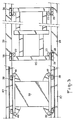
- Figures 3 and 4 respectively show sections along lines III-III and IV-IV of the object of FIG. 2. For the clarity of the representation, the working elements have been omitted in fig. 3.
- the machine shown in fig. 1 comprises a main chassis 1 comprising a platform 51 and two strong longitudinal members 37, and resting on the track 2, constituted by rails 3 and crosspieces 4 on a ballast bed 5, by means of bogies 6, 7
- the wheels 8 of the bogie 7 are coupled to a drive motor 9 making it possible to advance the machine during the working periods in the direction indicated by the arrow 10.
- the machine further comprises, at the front, a driving cabin 11 and an energy group 12 supplying in particular the engine 9 and the working members.
- These include a pair of lifting-shifting groups 13 (one per row of rails 3) and a pair of tamping groups 14 (also one per row of rails; alternatively, as shown, only one group can be provided. tamping, able to move transversely from one file of rails to another).
- Each lifting-shifting group 13 comprises a chassis 15 which can slide vertically along a column 16 under the action of a jack 17 to raise a file of rails gripped by two pairs of horizontal discs 18 carried by the chassis 15, and pivot horizontally around this column under the action of another jack to cause the line of rails to transversely slide through vertical discs 19 also carried by the chassis 15.
- Each tamping group 14 comprises a frame 20 which can slide vertically along a column 21 under the action of a jack 22 and carrying a pair of vibrating tamping tools 23, actuated by jacks 24, which can penetrate into the ballast 5 on either side of a cross 4.
- the working members 13, 14 are fixed below a mobile chassis 25, which can be displaced by driving them along the main chassis 1, where it is supported by four vertical rollers 26 and guided by four horizontal rollers 27.
- four other vertical rollers 28 take up the forces directed upwards can undergo the movable chassis 25.
- the rollers 26, 27, 28 cooperate with two lateral beams 29 belonging to the main chassis 1 and extending below the beams 37.
- the movable frame 25 is coupled by a driver 30 to the lower strand 31a of an endless chain 31 which extends horizontally in the median plane of the main frame 1 between two idler gears 32, 33 with horizontal axes 34, 35 fixed relative to the main chassis.
- One of these pinions is provided with a hydraulic gear motor group 36 for rotational drive.
- the lifting-shifting operations of track 2 are controlled by a leveling assembly with which the machine is equipped, which comprises a wire 43 stretched between the tops of two widely spaced vertical rods 44, 45 resting on the track by rollers 46, 47. Between them is disposed a track feeler carriage 48 supporting a vertical rod 49 at the top of which is placed a displacement sensor 50 which, in as a function of the position it takes with respect to the wire 43, controls the leveling-shifting groups 13 in leveling.
- a leveling assembly with which the machine is equipped, which comprises a wire 43 stretched between the tops of two widely spaced vertical rods 44, 45 resting on the track by rollers 46, 47. Between them is disposed a track feeler carriage 48 supporting a vertical rod 49 at the top of which is placed a displacement sensor 50 which, in as a function of the position it takes with respect to the wire 43, controls the leveling-shifting groups 13 in leveling.
- Another similar assembly provides the lateral control relating to the corrections of track layout.
- a mass 38 forming a counterweight with respect to the movable frame 25 and its working members 13, 14.
- This counterweight can be move in translation, supported by four vertical rollers 39, and guided by four horizontal rollers 40, following a rectilinear path parallel to the path of movement of the movable frame 25. It is for this purpose provided with a driver 42 engaged with the upper strand 31 b of the chain 31.
- the counterweight 38 including its annexes, has a mass equal to the working assembly 25, 13, 14 and its annexes. The distances traveled by these mobile elements are constantly equal, with equal speeds but in opposite directions thanks to the synchronization of their movements operated by the chain 31.
- two independent translation drive systems can be provided, one for the movable frame 25 and the other for the counterweight 38, each of them comprising for example an endless chain actuated by a hydraulic motor as well as described above, or a hydraulic cylinder horizontal connected to the main chassis.
- the synchronization of the opposite movements is no longer carried out mechanically, but electro-hydraulically: two potentiometric sensors can be provided for this purpose measuring the distance traveled respectively by the movable chassis and by the counterweight, which according to a control law in common speed, vary the flow rate of the two hydraulic translation motors or cylinders by means of an electro-hydraulic valve with proportional action.
- the amount of compensating movement, equal to and opposite to that of the movable chassis is carried out using a counterweight of smaller mass than that of the movable chassis, but animated by 'a speed greater than that of the latter, the ratio between the masses being equal to the inverse ratio of the respective speeds.
- This embodiment has the advantage of reducing the weights involved. However, it requires different strokes for the mobile chassis and for the counterweight.
- the synchronization systems must ensure here a different speed ratio from the unit corresponding for example to a ratio of pinions, displacements of drive motors or different sections of hydraulic cylinders.
Landscapes
- Engineering & Computer Science (AREA)
- Architecture (AREA)
- Civil Engineering (AREA)
- Structural Engineering (AREA)
- Machines For Laying And Maintaining Railways (AREA)
- Train Traffic Observation, Control, And Security (AREA)
- Control Of Multiple Motors (AREA)
- Feeding Of Workpieces (AREA)
- Specific Conveyance Elements (AREA)
Description
- L'invention se rapporte à un engin de travaux sur voie ferrée à avancement continu, comprenant un châssis principal doté d'organes de roulement sur la voie et un châssis auxiliaire supportant des organes de travail tels que des groupes de bourrage de ballast et de relevage-ripage de voie, ce dernier châssis étant mobile et pouvant se déplacer en translation le long du châssis principal sous l'action de moyens d'entraînement de façon à avancer, au cours des travaux, pas à pas par rapport à la voie tandis que l'engin progresse de façon continue.
- Un engin de ce genre se caractérise, en fonctionnement, par un avancement continu du châssis principal auquel se superpose un avancement discontinu du châssis mobile supportant les organes de travail. Ce dernier doit en effet, dans le cas notamment d'une machine à bourrer la voie, démarrer, freiner et s'arrêter à chaque cycle de travail, sur un trajet de déplacement relativement court déterminé par exemple par un intervalle de 50 à 60 cm entre les traverses de la voie.
- On connaît déjà des bourreuses de voies ferrées conçues à cet effet, dans lesquelles le châssis mobile porteur des organes de bourrage et de relevage-ripage est réalisé à partir d'un châssis reposant à l'arrière sur un essieu circulant sur les rails entre les organes de roulement du châssis principal de la bourreuse. Ce châssis est muni à sa partie avant de deux timons coulissant par rapport au châssis principal dans des dispositifs de guidage appropriés. Le châssis mobile est accéléré et freiné à chaque cycle de travail par un vérin lingitudinal, solidaire à une extrémité du châssis mobile et à l'autre extrémité du châssis principal de la bourreuse.
- Une bourreuse conçue selon ce principe permet d'obtenir une augmentation sensible du rendement en travail par rapport aux bourreuses dans lesquelles les organes de travail sont fixes par rapport au châssis principal et exigent donc, leur déplacement de traverse en traverse, l'accélération et le freinage de l'ensemble de la machine.
- Les bourreuses à avancement continu permettent, dans la phase de déplacement de traverse en traverse des organes de travail, de s'affranchir des conditions d'adhérence roues-rails et, en conséquence, de diminuer notablement la durée de cette phase, puisque les efforts d'accélération ou de décélération des organes de travail ne sont plus à transmettre sous la forme de couples moteurs agissant sur les roues de la machine circulant sur les rails. Les systèmes de translation des groupes de travail, caractérisant ce type de bourreuse, permettent en effet d'imprimer aux groupes de travail des efforts de trac- tio et de freinage beaucoup plus élevés.
- Un problème particulier à ce type de bourreuse à avancement continu réside cependant dans le compromis qu'il est nécessaire de trouver entre l'augmentation de rendement rendue théoriquement possible par le principe énoncé ci-dessus d'un châssis support des organes de travail en mouvement relatif par rapport au châssis principal de l'engin, et le confort du personnel de conduite situé dans les cabines solidaires du châssis principal.
- Les accélérations et décélérations du châssis mobile supportant les organes de travail qui apparaissent à chaque cycle de travail se traduisent, compte tenu du poids non négligeable de ce châssis mobile, par des réactions d'inertie longitudinales, se répercutant sur le châssis principal de la bourreuse et imprimant aux conducteurs situés dans les cabines des secousses importantes au début et à la fin de la phase déplacement. L'inconfort qui en résulte est d'autant plus sensible que l'on cherche à augmenter davantage le rendement de la bourreuse en accroissant la vitesse de déplacement du châssis mobile. Un autre effet de ces réactions d'inertie se manifeste dans une perte d'adhérence du châssis principal roulant sur les rails au moment où elles apparaissent. Cela nécessite en pratique de donner au châssis principal une charge motrice adhérente la plus élevée possible et conduit donc à des dépenses plus élevées au niveau de l'entraînement de l'engin.
- La présente invention se propose de fournir un engin à avancement continu, du type décrit ci-dessus, pour lequel les réactions d'inertie engendrées par les déplacements discontinus des organes de travail soient éliminées, de façon que l'augmentation de rendement en travail ne soit plus limitée par un inconfort croissant du personnel de conduite.
- L'invention réside dans le fait qu'un engin du genre considéré comprend en outre un contrepoids mobile, qui est couplé aux moyens d'entraînement du châssis mobile de façon à exécuter des mouvements de translation parallèles à ceux du châssis mobile mais de sens contraire, les quantités de mouvement respectives du contrepoids et du châssis mobile y compris ses organes de travail étant égales et opposées. Autrement dit, les vecteurs quantités de mouvement de ces éléments mobiles sont antiparallèles.
- Les réactions d'inertie du châssis mobile et du contrepoids mobile, égales et opposées, s'annulent en permenence, faisant ainsi disparaître toute sensation d'inconfort pour le personnel de conduite situé dans les cabines. Le rendement de l'engin peut, en conséquence, être augmenté par réduction du temps d'avancement pas à pas du châssis mobile et de ses organes de travail.
- Il convient que les centres de gravité respectifs du contrepoids et du châssis mobile y compris les organes de travail se déplacent sur des droites parallèles aussi rapprochées que possible, afin de minimiser les couples de tangage s'exerçant sur le châssis principal.
- Dans le cas le plus simple, on donnera au contrepoids une masse égale à la masse totale du châssis mobile et des organes qu'il supporte, sa vitesse de translation étant égale en module à celle du châssis mobile. Dans le but de réduire la masse totale de l'engin, on peut aussi donner au contrepoids une masse inférieure à la masse totale du châssis mobile et des organes qu'il supporte; sa vitesse de translation doit alors être supérieure en module à celle du châssis mobile, les modules des vitesses étant dans le rapport inverse des masses.
- Le contrepoids et le châssis mobile peuvent être actionnés en translation par un moyen moteur commun et être couplés entre eux par un moyen d'accouplement mécanique. Dans une forme d'exécution relative au cas où le châssis mobile, y compris les organes qu'il supporte, et le contrepoids ont une masse égale, ce moyen d'accouplement peut être constitué par une chaîne entraînée par un moteur commun et formant une boucle fermée à deux brins parallèles à la direction de déplacement du châssis mobile et du contrepoids, chacun de ces derniers étant couplé mécaniquement à l'un respectif desdits brins.
- Le contrepoids et le châssis mobile peuvent aussi être actionnés en translation par des moyens moteurs distincts et être couplés par des moyens de synchronisation. Ces moyens moteurs sont avantageusement des organes d'actionnement hydrauliques, couplés par des moyens de synchronisation électro-hydrauliques.
- D'autres caractéristiques et avantages de l'invention ressortiront plus clairement de la description qui va suivre, en regard des dessins annexés, d'un exemple de réalisation non limitatif.
- La fig. 1 représente schématiquement en élévation latérale un engin selon l'invention.
- La fig. 2 représente, à échelle agrandie, la partie de l'objet de la fig. 1 où se situent les organes de travail.
- Les figures 3 et 4 représentent respectivement des coupes suivant les lignes III-III et IV-IV de l'objet de la fig. 2. Pour la clarté de la représeantation, les organes de travail ont été omis sur la fig. 3.
- L'engin représenté à la fig. 1 comporte un châssis principal 1 comprenant une plate-forme 51 et deux forts longerons 37, et reposant sur la voie 2, constituée par des rails 3 et des traverses 4 sur un lit de ballast 5, par l'intermédiaire de bogies 6, 7. Les roues 8 du bogie 7 sont couplées à un moteur d'entraînement 9 permettant de faire avancer la machine durant les périodes de travail dans le sens indiqué par la flèche 10.
- L'engin comporte en outre, à l'avant, une cabine de conduite 11 et un groupe d'énergie 12 alimentant notamment le moteur 9 et les organes de travail.
- Ces derniers comprennent une paire de groupes de relevage-ripage 13 (un par file de rails 3) et une paire de groupes de bourrage 14 (également un par file de rails; en variante, comme représenté, on peut ne prévoir qu'un groupe de bourrage, capable de se déplacer transversalement d'une file de rails à l'autre).
- Chaque groupe de relevage-riparage 13 comprend un châssis 15 pouvant coullisser verticalement le long d'une colonne 16 sous l'action d'un vérin 17 pour relever une file de rails saisie par deux paires de disques horizontaux 18 portés par le châssis 15, et pivoter horizontalement autour de cette colonne sous l'action d'un autre vérin pour faire riper transversalement la file de rails par l'intermédiaire de disques verticaux 19 portés également par le châssis 15.
- Chaque groupe de bourrage 14 comporte un châssis 20 pouvant coulisser verticalement le long d'une colonne 21 sous l'action d'un vérin 22 et portant une paire d'outils vibrants de bourrage 23, actionnés par des vérins 24, qui peuvent pénétrer dans le ballast 5 de part et d'autre d'une traverse 4.
- Les organes de travail 13, 14 sontfixés dessous un châssis mobile 25, pouvant se déplaser en les entraînant le long du châssis principal 1, où il est supporté par quatre galets de roulement verticaux 26 et guidé par quatre galets horizontaux 27. En outre, quatre autres galets verticaux 28 reprennent les efforts dirigés vers le haut peut subir le châssis mobile 25. Les galets 26, 27, 28 coopèrent avec deux longerons latéraux 29 appartenant au châssis principal 1 et s'étendant au-dessous des longerons 37.
- Le châssis mobile 25 est couplé par un entraîneur 30 au brin inférieur 31 a d'une chaîne sans fin 31 qui s'étend horizontalement dans le plan médian du châssis principal 1 entre deux pignons de renvoi 32, 33 d'axes horizontaux 34, 35 fixes par rapport au châssis principal. L'un de ces pignons est doté d'un groupe moto-réducteur hydraulique 36 d'entraînement en rotation.
- Les opérations de relevage-ripage de la voie 2, destinées à éliminer les défauts d'alignement qu'elle peut présenter, sont pilotées par un ensemble de nivellement dont est équipé l'engin, qui comprend un fil 43 tendu entre les sommets de deux tiges verticales 44, 45 largement espacées, reposant sur la voie par des roulettes 46, 47. Entre celles-ci est disposé un chariot palpeur de voie 48 supportant une tige verticale 49 au sommet de laquelle est placé un capteur de déplacement 50 qui, en fonction de la position qu'il prend par rapport au fil 43, asservit en nivellement les groupes de relevage-ripage 13. Un autre ensemble analogue assure l'asservissement latéral relatif aux corrections de tracé de la voie.
- Entre des longerons 37 du châssis principal 1 est guidé en outre, par des plates-bandes 41 solidaires desdits longerons, une masse 38 formant contrepoids à l'égard du châssis mobile 25 et de ses organes de travail 13, 14. Ce contrepoids peut se déplacer en translation, supporté par quatre galets verticaux 39, et guidé par quatre galets horizontaux 40, suivant un chemin rectiligne parallèle au chemin de déplacement du châssis mobile 25. Il est à cet effet doté d'un entraîneur 42 en prise avec le brin supérieur 31 b de la chaîne 31. Le contrepoids 38, y compris ses annexes, présente une masse égale à l'ensemble de travail 25, 13, 14 et à ses annexes. Les distances parcourues par ces élémens mobiles sont constamment égales, avec des vitesses égales mais de sens opposés grâce à la synchronisation de leurs mouvements opérée par la chaîne 31.
- En fonctionnement, tous les mouvements de translation longitudinale communiqués à l'ensemble de travail par le groupe moto-réducteur 36, via la chaîne 31 par son brin inférieur 31 a, déterminent des mouvements de translation longitudinale égaux et en opposition de phase pour le contrepoids 38, de sorte que les efforts d'inertie engendrés par le déplacement pas à pas des groupes de travail sont annulés par compensation. Ainsi, les mouvements des groupes de travail, même les plus brutaux, qui correspondent à leur passage rapide d'une traverse 4 à la traverse suivante entre deux opérations de bourrage, n'induisent aucune secousse néfaste dans le châssis principal 1 et l'ensemble de l'engin.
- En variante, on peut prévoir deux systèmes d'entraînement en translation indépendants, l'un pour le châssis mobile 25 et l'autre pour le contrepoids 38, chacun d'eux comprenant par exemple une chaîne sans fin actionnée par un moteur hydraulique ainsi que décrit ci-dessus, ou un vérin hydraulique horizontal relié au châssis principal. La synchronisation des mouvements contraires n'est alors plus réalisée mécaniquement, mais électro-hydraulique- ment: on peut prévoir à cet effet deux capteurs potentiométriques mesurant la distance parcourue respectivement par le châssis mobile et par le contrepoids, qui selon une loi de commande en vitesse commune, font varier le débit des deux moteurs ou vérins hydrauliques de translation au moyen d'une soupape électro-hydraulique à action proportionnele.
- Dans un autre mode de réalisation de l'invention, la quantité de mouvement de compensation, égale et opposée à celle du châssis mobile, est réalisée à l'aide d'un contrepoids de masse plus faible que celle du châssis mobile, mais animé d'une vitesse supérieure à celle de ce dernier, le rapport entre les masses étant égal au rapport inverse des vitesses respectives. Cette forme de réalisation présente l'avantage de diminuer les poids mis en jeu. Elle nécessite cependant des courses différentes pour le châssis mobile et pour le contrepoids. Les systèmes de synchronisation doivent assurer ici un rapport des vitesses différent de l'unité correspondant par exemple à un rapport de pignons, des cylindrées de moteurs d'entraînement ou des sections de vérins hydrauliques différents.
Claims (7)
Priority Applications (1)
| Application Number | Priority Date | Filing Date | Title |
|---|---|---|---|
| AT85400144T ATE30445T1 (de) | 1984-02-06 | 1985-01-29 | Kontinuierlich fortschreitende schienenfahrbare arbeitsmaschine. |
Applications Claiming Priority (2)
| Application Number | Priority Date | Filing Date | Title |
|---|---|---|---|
| FR8401771 | 1984-02-06 | ||
| FR8401771A FR2559174B1 (fr) | 1984-02-06 | 1984-02-06 | Engin de travaux sur voie ferree a avancement continu |
Publications (2)
| Publication Number | Publication Date |
|---|---|
| EP0153213A1 EP0153213A1 (fr) | 1985-08-28 |
| EP0153213B1 true EP0153213B1 (fr) | 1987-10-28 |
Family
ID=9300785
Family Applications (1)
| Application Number | Title | Priority Date | Filing Date |
|---|---|---|---|
| EP85400144A Expired EP0153213B1 (fr) | 1984-02-06 | 1985-01-29 | Engin de travaux sur voie ferrée à avancement continu |
Country Status (5)
| Country | Link |
|---|---|
| US (1) | US4733614A (fr) |
| EP (1) | EP0153213B1 (fr) |
| AT (1) | ATE30445T1 (fr) |
| DE (1) | DE3560840D1 (fr) |
| FR (1) | FR2559174B1 (fr) |
Families Citing this family (11)
| Publication number | Priority date | Publication date | Assignee | Title |
|---|---|---|---|---|
| CA1269948A (fr) * | 1986-07-30 | 1990-06-05 | Leon A. Pintsov | Insereuse a selection par priorite des pieces a inserer |
| US4794861A (en) * | 1986-10-13 | 1989-01-03 | Franz Plasser Bahnbaumaschinen-Industriegesellschaft M.B.H. | Tie exchange method |
| EP0584055B1 (fr) * | 1992-08-12 | 1996-06-12 | Franz Plasser Bahnbaumaschinen-Industriegesellschaft m.b.H. | Machine de bourrage des aiguilles et croisements d'une voie |
| US5431107A (en) * | 1994-01-27 | 1995-07-11 | Racine Railroad Products, Inc. | Rail clip setter and method for fixing spring clips without fully tensioning the clips on the rails |
| US5584247A (en) * | 1994-01-27 | 1996-12-17 | Racine Railroad Products, Inc. | Rail clip applicator |
| AT3876U3 (de) * | 2000-06-09 | 2001-02-26 | Plasser Bahnbaumasch Franz | Verfahren und maschine zur unterstopfung eines gleises |
| AT411276B (de) * | 2001-08-24 | 2003-11-25 | Plasser Bahnbaumasch Franz | Maschine zur bearbeitung eines gleises |
| US6595140B1 (en) | 2002-06-05 | 2003-07-22 | Harsco Technologies Corporation | Railway tie plate insertion apparatus and method |
| US8528484B2 (en) | 2009-03-04 | 2013-09-10 | H & H Railroad Contracting, Inc. | Railroad tie plate apparatus and method |
| US8132512B2 (en) | 2009-03-04 | 2012-03-13 | H & H Railroad Contracting, Inc. | Railroad tie plate apparatus and method |
| US11668054B2 (en) | 2020-03-02 | 2023-06-06 | Herzog Railroad Services, Inc. | Railroad tie plate apparatus and method |
Family Cites Families (10)
| Publication number | Priority date | Publication date | Assignee | Title |
|---|---|---|---|---|
| US3322379A (en) * | 1964-11-03 | 1967-05-30 | Kaman Aircraft Corp | Dynamic antiresonant vibration isolator |
| AT294168B (de) * | 1964-11-30 | 1971-11-10 | Plasser Bahnbaumasch Franz | Fahrbare Gleisstopfmaschine und Verfahren zum Unterstopfen der Querschwellen eines Gleises |
| AT314581B (de) * | 1969-07-24 | 1974-04-10 | Plasser Bahnbaumasch Franz | Bettungsverdichtmaschine |
| GB1317301A (en) * | 1970-04-30 | 1973-05-16 | Davy & United Eng Co Ltd | Forging manipulator |
| AT345325B (de) * | 1975-06-20 | 1978-09-11 | Plasser Bahnbaumasch Franz | Gleisstopfmaschine, insbesondere gleisstopf- und nivelliermaschine |
| DE2603689C3 (de) * | 1976-01-31 | 1979-02-22 | Ibm Deutschland Gmbh, 7000 Stuttgart | Anordnung zum Schwingungsausgleich |
| ZA796444B (en) * | 1978-11-30 | 1980-11-26 | Pandrol Ltd | Apparatus for performing operations on a railway track |
| US4360087A (en) * | 1980-05-27 | 1982-11-23 | Mechanical Technology Incorporated | Suspension and vibration isolation system for a linear reciprocating machine |
| DE3117898A1 (de) * | 1980-07-24 | 1982-03-04 | Franz Plasser Bahnbaumaschinen-Industriegesellschaft mbH, 1010 Wien | Fahrbare anlage und verfahren zur gleisunterbau-sanierung |
| AT376259B (de) * | 1982-09-09 | 1984-10-25 | Plasser Bahnbaumasch Franz | Werkzeuganordnung fuer eine vollstaendige gleislagekorrektur |
-
1984
- 1984-02-06 FR FR8401771A patent/FR2559174B1/fr not_active Expired
-
1985
- 1985-01-29 EP EP85400144A patent/EP0153213B1/fr not_active Expired
- 1985-01-29 AT AT85400144T patent/ATE30445T1/de not_active IP Right Cessation
- 1985-01-29 DE DE8585400144T patent/DE3560840D1/de not_active Expired
- 1985-02-04 US US06/698,116 patent/US4733614A/en not_active Expired - Fee Related
Also Published As
| Publication number | Publication date |
|---|---|
| FR2559174B1 (fr) | 1986-10-24 |
| DE3560840D1 (en) | 1987-12-03 |
| EP0153213A1 (fr) | 1985-08-28 |
| FR2559174A1 (fr) | 1985-08-09 |
| US4733614A (en) | 1988-03-29 |
| ATE30445T1 (de) | 1987-11-15 |
Similar Documents
| Publication | Publication Date | Title |
|---|---|---|
| EP0153213B1 (fr) | Engin de travaux sur voie ferrée à avancement continu | |
| CN102328829B (zh) | 托盘上下架装置 | |
| FR2586012A1 (fr) | Installation de transfert de pieces | |
| FR2532967A1 (fr) | Machine roulante de bourrage de voie ferree a deux chassis de vehicule roulant relies entre eux de facon articulee | |
| FR2532968A1 (fr) | Agencement d'outils pour bourrage par en dessous, nivellement et dressage lateral d'une voie ferree | |
| FR2556752A1 (fr) | Machine de bourrage de voie ferree deplacable par roulement de facon continue | |
| EP0057030B1 (fr) | Machine à bourrer les voies ferrées | |
| EP0161117B1 (fr) | Engin à avancement continu pour travaux sur voie ferrée | |
| FR2553124A1 (fr) | Machine roulante de bourrage, de nivellement, et de dressage de voie ferree | |
| EP0310481B1 (fr) | Dispositif pour déplacer un mobile, et en particulier un préhenseur de manutention dans un plan vertical | |
| FR2565269A1 (fr) | Machine de bourrage, de nivellement et de dressage de voie ferree deplacable par roulement de facon continue | |
| FR2482882A1 (fr) | Verins d'avance et de suspension elastique de machoire, sur des manipulateurs de forge, comprenant respectivement un verin median dispose entre deux verins exterieurs | |
| FR2550809A1 (fr) | Machine de bourrage, de nivellement et de dressage de voie ferree deplacable par roulement de facon continue (sans arret) a chassis separe de support d'outils | |
| FR2552460A1 (fr) | Machine de bourrage, de nivellement et de dressage de voie ferree deplacable par roulement de facon continue (sans arret) | |
| FR2551782A1 (fr) | Machine de bourrage, de nivellement et de dressage de voie ferree deplacable de facon continue (sans arret) | |
| FR2550808A1 (fr) | Machine de bourrage, de nivellement et de dressage de voie ferree deplacable de facon continue (sans arret) avec attenuation des chocs pour les operateurs | |
| US3638578A (en) | Apparatus for consolidating a track bed | |
| CN116901643B (zh) | 一种面向电力智慧工地的自动搬运机器人 | |
| CN209760762U (zh) | 可自由变轨式滑梯 | |
| CH628378A5 (en) | Movable machine for working on railway tracks | |
| CH651338A5 (fr) | Machine de chantier ferroviaire pour le remplacement d'un troncon ou d'un appareil de voie monte. | |
| RU2022240C1 (ru) | Стенд для исследования процессов взаимодействия рабочих органов машин с грунтом | |
| CN208668426U (zh) | 一种用于基坑的移动遮蔽装置 | |
| GB2027777A (en) | Continuosly advancing track-tamping machine | |
| SU1145143A1 (ru) | Штабелююща машина |
Legal Events
| Date | Code | Title | Description |
|---|---|---|---|
| PUAI | Public reference made under article 153(3) epc to a published international application that has entered the european phase |
Free format text: ORIGINAL CODE: 0009012 |
|
| AK | Designated contracting states |
Designated state(s): AT BE DE GB IT NL SE |
|
| 17P | Request for examination filed |
Effective date: 19860219 |
|
| 17Q | First examination report despatched |
Effective date: 19870119 |
|
| GRAA | (expected) grant |
Free format text: ORIGINAL CODE: 0009210 |
|
| ITF | It: translation for a ep patent filed |
Owner name: MARCHI & MITTLER S.R.L. |
|
| AK | Designated contracting states |
Kind code of ref document: B1 Designated state(s): AT BE DE GB IT NL SE |
|
| REF | Corresponds to: |
Ref document number: 30445 Country of ref document: AT Date of ref document: 19871115 Kind code of ref document: T |
|
| REF | Corresponds to: |
Ref document number: 3560840 Country of ref document: DE Date of ref document: 19871203 |
|
| GBT | Gb: translation of ep patent filed (gb section 77(6)(a)/1977) | ||
| PLBE | No opposition filed within time limit |
Free format text: ORIGINAL CODE: 0009261 |
|
| STAA | Information on the status of an ep patent application or granted ep patent |
Free format text: STATUS: NO OPPOSITION FILED WITHIN TIME LIMIT |
|
| 26N | No opposition filed | ||
| PGFP | Annual fee paid to national office [announced via postgrant information from national office to epo] |
Ref country code: AT Payment date: 19911219 Year of fee payment: 8 |
|
| PGFP | Annual fee paid to national office [announced via postgrant information from national office to epo] |
Ref country code: DE Payment date: 19920118 Year of fee payment: 8 |
|
| PGFP | Annual fee paid to national office [announced via postgrant information from national office to epo] |
Ref country code: SE Payment date: 19920121 Year of fee payment: 8 Ref country code: GB Payment date: 19920121 Year of fee payment: 8 |
|
| ITTA | It: last paid annual fee | ||
| PGFP | Annual fee paid to national office [announced via postgrant information from national office to epo] |
Ref country code: NL Payment date: 19920131 Year of fee payment: 8 |
|
| PGFP | Annual fee paid to national office [announced via postgrant information from national office to epo] |
Ref country code: BE Payment date: 19920514 Year of fee payment: 8 |
|
| PG25 | Lapsed in a contracting state [announced via postgrant information from national office to epo] |
Ref country code: GB Effective date: 19930129 Ref country code: AT Effective date: 19930129 |
|
| PG25 | Lapsed in a contracting state [announced via postgrant information from national office to epo] |
Ref country code: SE Effective date: 19930130 |
|
| PG25 | Lapsed in a contracting state [announced via postgrant information from national office to epo] |
Ref country code: BE Effective date: 19930131 |
|
| BERE | Be: lapsed |
Owner name: FRAMAFER Effective date: 19930131 |
|
| PG25 | Lapsed in a contracting state [announced via postgrant information from national office to epo] |
Ref country code: NL Effective date: 19930801 |
|
| NLV4 | Nl: lapsed or anulled due to non-payment of the annual fee | ||
| GBPC | Gb: european patent ceased through non-payment of renewal fee |
Effective date: 19930129 |
|
| PG25 | Lapsed in a contracting state [announced via postgrant information from national office to epo] |
Ref country code: DE Effective date: 19931001 |
|
| EUG | Se: european patent has lapsed |
Ref document number: 85400144.3 Effective date: 19930810 |