EP0152374A2 - Werkzeugträger - Google Patents
Werkzeugträger Download PDFInfo
- Publication number
- EP0152374A2 EP0152374A2 EP85810035A EP85810035A EP0152374A2 EP 0152374 A2 EP0152374 A2 EP 0152374A2 EP 85810035 A EP85810035 A EP 85810035A EP 85810035 A EP85810035 A EP 85810035A EP 0152374 A2 EP0152374 A2 EP 0152374A2
- Authority
- EP
- European Patent Office
- Prior art keywords
- tool
- guides
- insert
- carrier according
- tool carrier
- Prior art date
- Legal status (The legal status is an assumption and is not a legal conclusion. Google has not performed a legal analysis and makes no representation as to the accuracy of the status listed.)
- Granted
Links
Images

Classifications
-
- B—PERFORMING OPERATIONS; TRANSPORTING
- B25—HAND TOOLS; PORTABLE POWER-DRIVEN TOOLS; MANIPULATORS
- B25H—WORKSHOP EQUIPMENT, e.g. FOR MARKING-OUT WORK; STORAGE MEANS FOR WORKSHOPS
- B25H3/00—Storage means or arrangements for workshops facilitating access to, or handling of, work tools or instruments
- B25H3/06—Trays
Definitions
- the present invention relates to a tool carrier for receiving tools with a cylindrical or tapered shank according to the preamble of claim 1.
- a known tool carrier consists of a frame with a base and two parallel rails, into which tool holding profiles can be inserted.
- the tools can be inserted between two profiles that are screwed at a distance corresponding to the diameter of the tool to be carried. If the dimension of one of the tools changes, all profiles must be moved and readjusted.
- Another known tool holder consists of a frame in which inserts can be hung, each of which is precisely matched to the diameter and taper of the tool to be received and can only be used for this.
- Such inserts are probably an optimal shot for the tool, however, they require that the exact number of tools, their diameter and their taper must be known in advance before buying the cabinet or trolley that receives the tool holder.
- a subsequent change in the division of the currently approx. 12 different shaft designs requires an inefficiently large stock of inserts to be maintained.
- the aim of the present invention is to create a tool holder which can universally accommodate all known shaft shapes and dimensions. Another goal is to make the tool holder or each individual mounting point in the tool holder switchable to a different tool diameter at any time, without the need to purchase new parts or use tools.
- All tool carriers are recessed with uniform recesses and inserts and in a uniform division either directly in the bottom of a drawer or in a shelf of a frame.
- the same tab can be used for all diameters of each shaft standard (ISO, Morse or cylinder).
- the drawers for tools do not require substructures for the tool carriers; the tool carrier itself forms the supporting frame for the guide rails and the front plate.
- guides 2 are visible, in this example there are three, with lateral grooves 3, a central opening 4 and its center Z. All guides 2 are arranged radially to the center Z and are of the same shape and size.
- a flange 5 is attached in the upper part of the insert 1, which is in contact with the one set 1 carrying plate 6 (shown in broken lines).
- the plate 6 can be part of a drawer 7 or a frame 8, which are described in more detail in FIGS. 4 and 5; the plate 6 can also be part of an insert frame which can be inserted into a conventional drawer or cupboard.
- the lateral grooves 3 in the guides 2 run parallel and are at a constant distance of 5 mm from one another and are provided with the standardized designation of the tools. Riders 9 are inserted into the guides 2, their curved surfaces 10 directed towards the center Z form part of a - in this example - conical opening 4 '.
- the diameter d and the angle of inclination oC of the surface 10 of the slide 9 relative to the axis A through the center Z correspond to the design of the shank of a tool to be carried.
- the drawer 7 does not consist of a trough forming the drawer into which tool carriers are placed, but the tool carrier - the plate 6 - itself forms the drawer 7.
- the plate 6 has laterally folded surfaces 14 , on which guide rails 15 are attached for a pull-out device.
- a drawer front panel 16 is attached to the front of the panel 6 with a handle 17.
- recesses 19 for the inserts 1 are punched out.
- the inserts 1 are inserted into these exceptions 19 and are there known means, e.g. held on the inserts 1 barbs 20 ( Figure 2).
- a floor below part 18 is not necessary.
- the contour 19 'of the recesses 19 is preferably designed according to the line shown in Figure 1.
- the plates 6 carrying the inserts 1 are attached to the side walls 21 at an angle to the horizontal. All plates 6 have identical recesses 19 for all commercially available tools.
- the plates 6 with the recesses 19 can also be used as portable and in existing conventional ones Drawers or units that can be inserted into cupboards. Even then, they have all the advantages of the unlimited possibilities for subsequent tool and format changes.
- the invention is of course not limited to the embodiment shown with three guides 2 for receiving three riders 9; two diagonally arranged riders 9 can also perform the same task.
- Grooves 3 and ribs 13 other than rectangular are also possible without disadvantages.
Landscapes
- Engineering & Computer Science (AREA)
- Mechanical Engineering (AREA)
- Workshop Equipment, Work Benches, Supports, Or Storage Means (AREA)
- Liquid Deposition Of Substances Of Which Semiconductor Devices Are Composed (AREA)
- Gripping On Spindles (AREA)
- Crystals, And After-Treatments Of Crystals (AREA)
- Constituent Portions Of Griding Lathes, Driving, Sensing And Control (AREA)
- Drawers Of Furniture (AREA)
Abstract
Description
- Die vorliegende Erfindung betrifft einen Werkzeugträger zur Aufnahme von Werkzeugen mit Zylinder- oder Kegelschaft gemäss Oberbegriff des Patentanspruches 1.
- Bei Werkzeugträgern zum Lagern und/oder Transportieren von Werkzeugen insbesondere für NC-Werkzeugmaschinen besteht das Problem, diese jeweils an die unterschiedlichen Durchmesser und Konizitäten der Schäfte der Werkzeuge anzupassen.
- Ein bekannter Werkzeugträger,besteht aus einem Rahmen mit Boden und zwei parallel zueinander verlaufenden Schienen, in die Werkzeughalteprofile eingeschoben werden können. Zwischen je zwei Profilen, die in einem Abstand entsprechend dem Durchmesser des zu tragenden Werkzeuges festgeschraubt sind, können die Werkzeuge eingesteckt werden. Aendert die Dimension eines der Werkzeuge, so müssen alle Profile verschoben und neu eingestellt werden.
- Ein weiterer bekannter Werkzeugträger besteht aus einem Rahmen, in welchen Einsätze eingehängt werden können, die jeweils genau auf den Durchmesser und die Konizität des aufzunehmenden Werkzeuges abgestimmt und nur für diese benutzbar sind. Derartige Einsätze stellen wohl eine optimale Aufnahme für das Werkzeug dar, sie bedingen jedoch, dass vor dem Kauf des die Werkzeugträger aufnehmenden Schrankes oder Wagens die genaue Anzahl der Werkzeuge, deren Durchmesser sowie deren Konizität zum voraus bekannt sein müssen. Eine nachträgliche Aenderung in der Aufteilung der zur Zeit ca. 12 verschiedenen Schaftausführungen bedingt Haltung eines unrationell grossen Lagers an Einsätzen.
- Ziel der vorliegenden Erfindung ist die Schaffung eines Werkzeugträgers, der universell alle bekannten Schaftformen und -dimensionen aufnehmen kann. Ein weiteres Ziel besteht darin, den Werkzeugträger bzw. jede einzelne Aufnahmestelle im Werkzeugträger jederzeit auf einen anderen Werkzeucdurchmesser umstellbar zu machen, ohne dass dazu weder neue Teile zugekauft, noch Werkzeuge verwendet werden müssen.
- Nach der Erfindung werden diese Aufgaben gemäss den kennzeichnenden Merkmalen des Patentanspruches 1 gelöst. Weitere vorteilhafte Ausführungsformen sind in den abhängigen Ansprüchen beschrieben.
- Alle Werkzeugträger sind mit einheitlichen Aussparungen und Einsätzen und in einheitlicher Teilung entweder direkt im Boden einer Schublade oder in ein Tablar eines Gestells eingelassen. Für alle Durchmesser jeder Schaftnorm (ISO, Morse oder Zylinder) können jeweils dieselben Reiter verwendet werden.
- Die drei Reiterformen unterscheiden sich einzig an der dem Werkzeug zugewendeten Auflagefläche und sind als preisgünstige Kunststoffteile ausgelegt.
- Die Schubladen für Werkzeuge benötigen keine Unterbauten für die Werkzeugträger; der Werkzeugträger selbst bildet das tragende Gerüst für die Führungsschienen und die Frontplatte.
- Anhand illustrierter Ausführungsbeispiele wird die Erfindung näher beschrieben. Es zeigen:
- Figur 1 einen Grundriss eines Einsatzes,
- Figur 2 einen Querschnitt durch den Einsatz nach Fig. 1 längs Linie II-II, jedoch ohne Reiter,
- Figur 3 eine Ansicht eines Reiters,
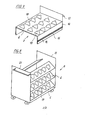
- Figur 4 eine Schublade mit Aussparungen für Einsätze,
- Figur 5 einen Wagen mit Gestellen und darin angebrachten Aussparungen.
- Im Grundriss des in Figur 1 dargestellten Einsatzes 1 sind Führungen 2, in diesem Beispiel sind es drei, mit seitlichen Nuten 3, eine zentrale Oeffnung 4 und deren Zentrum Z sichtbar. Alle Führungen 2 sind radial zum Zentrum Z angeordnet und von gleicherGestalt und Grösse. Im Querschnitt nach Figur 2 ist im oberen Teil des Einsatzes 1 ein Flansch 5 angebracht, der in Anlage mit einer den Einsatz 1 tragenden Platte 6 (in gebrochenen Linien dargestellt) gelangt. Die Platte 6 kann Teil einer Schublade 7 oder eines Gestells 8 sein, welche in den Figuren 4 bzw. 5 näher beschrieben werden; die Platte 6 kann auch Teil eines in eine herkömmliche Schublade oder einen Schrank einfügbaren Einsatzrahmens sein.
- Die seitlichen Nuten 3 in den Führungen 2 verlaufen parallel und liegen in einem konstanten Abstand von 5 mm zueinander und sind mit der normierten Bezeichnung der Werkzeuge versehen. In den Führungen 2 sind Reiter 9 eingesteckt, deren bogenförmig verlaufende, gegen das Zentrum Z gerichtete Flächen 10 Teil einer - in diesem Beispiel - kegelförmigen Oeffnung 4' bilden. Der Durchmesser d sowie der NeigungswinkeloC der Fläche 10 des Reiters 9 zur Achse A durch das Zentrum Z (Figur 3) entsprechen der Ausbildung des zu tragenden Schaftes eines Werkzeuges. In Figur 2 ist ein Beispiel eines ISO-Schaftes mit Durchmesser d = 40 dargestellt. Damit der jeweilige Durchmesser leicht eingestellt werden kann, sind seitlich der Nuten 3 die entsprechenden Angaben vorgesehen.
- Für die drei handelsüblichen Schaftausbildungen von Werkzeugen, den ISO-Steilkegel nach DIN 2080/ISO 297, den Morsekegel nach DIN 228 und die Zylinderschäfte nach VDI 3425 sind folglich drei verschiedene Reiter 9 notwendig, deren Flächen 10 entsprechende Winkel α aufweisen. Die beiden Rippenpaare 13, welche in die Nuten 3 eingreifen sind - wie auch der Einsatz 1 - bei allen Reitern 9 identisch.
- Im Gegensatz zu den herkömmlichen Schubladen besteht die Schublade 7 nach der Erfindung nicht aus einer die Schublade bildenden Wanne, in welche Werkzeugträger hineingestellt werden, sondern der Werkzeugträger - die Platte 6 - bildet selbst die Schublade 7. Die Platte 6 weist seitlich abgekantete Flächen 14 auf, an denen Führungsschienen 15 für eine Auszugsvorrichtung angebracht sind. Stirnseitig ist eine Schubladenfrontplatte 16 mit einer Griffleiste 17 an der Platte 6 befestigt. Im horizontal liegenden Teil 18 der Platte 6 sind Ausnehmungen 19 für die Einsätze 1 ausgestanzt. Die Einsätze 1 sind in diese Ausnahmungen 19 eingesteckt und werden dort mit bekannten Mitteln, z.B. an den Einsätzen 1 angebrachten Widerhaken 20 (Figur 2) gehalten. Ein Boden unterhalb dem Teil 18 ist nicht notwendig. Die Kontur 19' der Ausnehmungen 19 ist vorzugsweise entsprechend der in Figur 1 dargestellten Linie ausgeführt. Im Transportgestell 8 nach Figur 5 sind, analog zur Schublade 7, die die Einsätze 1 tragenden Platten 6 geneigt zur Horizontalen an den Seitenwänden 21 befestigt. Alle Platten 6 weisen identische Ausnehmungen 19 für alle handelsüblichen Werkzeuge auf.
- Selbstverständlich können die Platten 6 mit den Ausnehmungen 19 auch als tragbare und in bestehende herkömmliche Schubladen oder in Schränke einfügbare Einheiten ausgebildet sein. Sie weisen auch dann alle Vorteile der unbeschränkten Möglichkeiten beim nachträglichen Werkzeug- und Formatwechsel auf.
- Die Erfindung ist natürlich nicht auf die gezeigte Ausführungsform mit drei Führungen 2 zur Aufnahme von drei Reitern 9 eingeschränkt; es können auch zwei diagonal angeordneten Reiter 9 dieselbe Aufgabe erfüllen. Dasselbe trifft auch auf die Ausbildung der Nuten 3 zu. Ohne Nachteile sind auch andere als rechteckig geformte Nuten 3 und Rippen 13 möglich.
Claims (9)
Priority Applications (1)
| Application Number | Priority Date | Filing Date | Title |
|---|---|---|---|
| AT85810035T ATE31500T1 (de) | 1984-02-10 | 1985-02-04 | Werkzeugtraeger. |
Applications Claiming Priority (2)
| Application Number | Priority Date | Filing Date | Title |
|---|---|---|---|
| CH640/84A CH665991A5 (de) | 1984-02-10 | 1984-02-10 | Werkzeugtraeger. |
| CH640/84 | 1984-02-10 |
Publications (3)
| Publication Number | Publication Date |
|---|---|
| EP0152374A2 true EP0152374A2 (de) | 1985-08-21 |
| EP0152374A3 EP0152374A3 (en) | 1986-05-07 |
| EP0152374B1 EP0152374B1 (de) | 1987-12-23 |
Family
ID=4191719
Family Applications (1)
| Application Number | Title | Priority Date | Filing Date |
|---|---|---|---|
| EP85810035A Expired EP0152374B1 (de) | 1984-02-10 | 1985-02-04 | Werkzeugträger |
Country Status (4)
| Country | Link |
|---|---|
| EP (1) | EP0152374B1 (de) |
| AT (1) | ATE31500T1 (de) |
| CH (1) | CH665991A5 (de) |
| DE (1) | DE3561234D1 (de) |
Cited By (2)
| Publication number | Priority date | Publication date | Assignee | Title |
|---|---|---|---|---|
| EP0192977A1 (de) * | 1985-02-16 | 1986-09-03 | GEWEFA Josef C. Pfister GmbH & Co. | Aufnahmeträger für Werkzeuge |
| EP3552771A3 (de) * | 2018-01-25 | 2019-12-25 | E. Zoller GmbH & Co. KG Einstell- und Messgeräte | Werkzeugeinsatz und/oder werkzeugaufnahmeeinsatz, werkzeugeinsatz- und/oder werkzeugaufnahmeeinsatzsystem und werkzeug- und/oder werkzeugaufnahmelagersystem |
Family Cites Families (5)
| Publication number | Priority date | Publication date | Assignee | Title |
|---|---|---|---|---|
| US1641179A (en) * | 1924-09-03 | 1927-09-06 | Gen Chemical Corp | Carboy package |
| US2256995A (en) * | 1939-08-21 | 1941-09-23 | Hinde & Dauch Paper Co | Box |
| GB1021787A (en) * | 1964-01-25 | 1966-03-09 | James Chapman | Improvements in or relating to storage racks |
| FR1527130A (fr) * | 1967-04-13 | 1968-05-31 | Allibert Ets | Boîte pour bobines de fils |
| DE3234773C2 (de) * | 1982-09-20 | 1985-04-04 | Autz & Herrmann, 6900 Heidelberg | Werkzeugablageeinrichtung |
-
1984
- 1984-02-10 CH CH640/84A patent/CH665991A5/de not_active IP Right Cessation
-
1985
- 1985-02-04 EP EP85810035A patent/EP0152374B1/de not_active Expired
- 1985-02-04 DE DE8585810035T patent/DE3561234D1/de not_active Expired
- 1985-02-04 AT AT85810035T patent/ATE31500T1/de not_active IP Right Cessation
Cited By (3)
| Publication number | Priority date | Publication date | Assignee | Title |
|---|---|---|---|---|
| EP0192977A1 (de) * | 1985-02-16 | 1986-09-03 | GEWEFA Josef C. Pfister GmbH & Co. | Aufnahmeträger für Werkzeuge |
| EP3552771A3 (de) * | 2018-01-25 | 2019-12-25 | E. Zoller GmbH & Co. KG Einstell- und Messgeräte | Werkzeugeinsatz und/oder werkzeugaufnahmeeinsatz, werkzeugeinsatz- und/oder werkzeugaufnahmeeinsatzsystem und werkzeug- und/oder werkzeugaufnahmelagersystem |
| US10710233B2 (en) | 2018-01-25 | 2020-07-14 | E. Zoller Gmbh & Co. Kg Einstell—Und Messgeräte | Tool insert and/or tool holder insert, tool insert system and/or tool holder insert system and tool storage system and/or tool holder storage system |
Also Published As
| Publication number | Publication date |
|---|---|
| DE3561234D1 (en) | 1988-02-04 |
| EP0152374A3 (en) | 1986-05-07 |
| CH665991A5 (de) | 1988-06-30 |
| ATE31500T1 (de) | 1988-01-15 |
| EP0152374B1 (de) | 1987-12-23 |
Similar Documents
| Publication | Publication Date | Title |
|---|---|---|
| DE2619151C3 (de) | Lagereinrichtung für Werkzeuge | |
| EP0152374B1 (de) | Werkzeugträger | |
| DE3401493A1 (de) | Positionsanzeigevorrichtung, insbesondere fuer umlaufregale | |
| EP0440909A1 (de) | Halter für Handwerkzeuge | |
| DE19822972A1 (de) | Vorrichtung zum lösbaren Festlegen von Gegenständen | |
| EP0123077A1 (de) | Werkzeug-Lagereinrichtung | |
| DE10253338B3 (de) | Aufbewahrungssystem für Werkzeugträger | |
| DE2215250C3 (de) | Vorrichtung zur Anordnung und Halterung schaftförmiger Werkzeuge und Teile | |
| DE3901331A1 (de) | Organisationsschublade mit inneneinteilungssystemen | |
| EP0362124B1 (de) | Werkzeugaufnahmesystem | |
| EP0771748A3 (de) | Vorrichtung zum ausgerichteten Zuführen und Auflockern von Stapeln flacher Gegenstände | |
| DE202016000783U1 (de) | Möbelgestell | |
| DE3234773A1 (de) | Werkzeugablageeinrichtung | |
| EP0902938A1 (de) | Halter für wendetafeln od. dgl. | |
| AT346151B (de) | Klemmhalter | |
| DD212989A1 (de) | Substrathalterung fuer die beschichtung von koerpern | |
| DE69710261T2 (de) | Klassifizierungssystem zum Sortieren | |
| DE8712177U1 (de) | Stapelbares Tray | |
| DE8803367U1 (de) | Vorrichtung zur Unterteilung eines Kofferraumes | |
| EP0248998A2 (de) | Element zum Halten von Gegenständen auf Transportmitteln | |
| DE29509781U1 (de) | Vorrichtung zum Lagern von flächenförmigen Gegenständen | |
| DE202020000986U1 (de) | CNC-Werkzeugträger | |
| EP0534330A1 (de) | Ablage für Gepäck, Hüte und dggl., insbesondere zum Einbau in Eisenbahnwaggons | |
| DE29608003U1 (de) | Vorrichtung zum Vereinzeln und Fördern länglicher Gegenstände , insbesondere Vereinzelungsanlage für Schreib-, Zeichen- oder Malgeräte | |
| DE29714995U1 (de) | Vorrichtung zum Halten von Audio- und/oder Video-Signalträgern |
Legal Events
| Date | Code | Title | Description |
|---|---|---|---|
| PUAI | Public reference made under article 153(3) epc to a published international application that has entered the european phase |
Free format text: ORIGINAL CODE: 0009012 |
|
| AK | Designated contracting states |
Designated state(s): AT BE CH DE FR GB LI NL SE |
|
| 17P | Request for examination filed |
Effective date: 19860118 |
|
| PUAL | Search report despatched |
Free format text: ORIGINAL CODE: 0009013 |
|
| AK | Designated contracting states |
Kind code of ref document: A3 Designated state(s): AT BE CH DE FR GB LI NL SE |
|
| RBV | Designated contracting states (corrected) |
Designated state(s): AT BE DE FR GB NL SE |
|
| 17Q | First examination report despatched |
Effective date: 19870616 |
|
| GRAA | (expected) grant |
Free format text: ORIGINAL CODE: 0009210 |
|
| AK | Designated contracting states |
Kind code of ref document: B1 Designated state(s): AT BE DE FR GB NL SE |
|
| REF | Corresponds to: |
Ref document number: 31500 Country of ref document: AT Date of ref document: 19880115 Kind code of ref document: T |
|
| ET | Fr: translation filed | ||
| REF | Corresponds to: |
Ref document number: 3561234 Country of ref document: DE Date of ref document: 19880204 |
|
| GBT | Gb: translation of ep patent filed (gb section 77(6)(a)/1977) | ||
| PLBE | No opposition filed within time limit |
Free format text: ORIGINAL CODE: 0009261 |
|
| STAA | Information on the status of an ep patent application or granted ep patent |
Free format text: STATUS: NO OPPOSITION FILED WITHIN TIME LIMIT |
|
| 26N | No opposition filed | ||
| PGFP | Annual fee paid to national office [announced via postgrant information from national office to epo] |
Ref country code: GB Payment date: 19920113 Year of fee payment: 8 |
|
| PGFP | Annual fee paid to national office [announced via postgrant information from national office to epo] |
Ref country code: AT Payment date: 19920120 Year of fee payment: 8 |
|
| PGFP | Annual fee paid to national office [announced via postgrant information from national office to epo] |
Ref country code: FR Payment date: 19920123 Year of fee payment: 8 |
|
| PGFP | Annual fee paid to national office [announced via postgrant information from national office to epo] |
Ref country code: SE Payment date: 19920128 Year of fee payment: 8 |
|
| PGFP | Annual fee paid to national office [announced via postgrant information from national office to epo] |
Ref country code: BE Payment date: 19920212 Year of fee payment: 8 |
|
| PGFP | Annual fee paid to national office [announced via postgrant information from national office to epo] |
Ref country code: NL Payment date: 19920229 Year of fee payment: 8 |
|
| PGFP | Annual fee paid to national office [announced via postgrant information from national office to epo] |
Ref country code: DE Payment date: 19920331 Year of fee payment: 8 |
|
| PG25 | Lapsed in a contracting state [announced via postgrant information from national office to epo] |
Ref country code: GB Effective date: 19930204 Ref country code: AT Effective date: 19930204 |
|
| PG25 | Lapsed in a contracting state [announced via postgrant information from national office to epo] |
Ref country code: SE Effective date: 19930205 |
|
| PG25 | Lapsed in a contracting state [announced via postgrant information from national office to epo] |
Ref country code: BE Effective date: 19930228 |
|
| BERE | Be: lapsed |
Owner name: MEIER GERD Effective date: 19930228 |
|
| PG25 | Lapsed in a contracting state [announced via postgrant information from national office to epo] |
Ref country code: NL Effective date: 19930901 |
|
| GBPC | Gb: european patent ceased through non-payment of renewal fee |
Effective date: 19930204 |
|
| NLV4 | Nl: lapsed or anulled due to non-payment of the annual fee | ||
| PG25 | Lapsed in a contracting state [announced via postgrant information from national office to epo] |
Ref country code: FR Effective date: 19931029 |
|
| PG25 | Lapsed in a contracting state [announced via postgrant information from national office to epo] |
Ref country code: DE Effective date: 19931103 |
|
| REG | Reference to a national code |
Ref country code: FR Ref legal event code: ST |
|
| EUG | Se: european patent has lapsed |
Ref document number: 85810035.7 Effective date: 19930912 |