EP0150744B1 - Lautsprechereinheit - Google Patents
Lautsprechereinheit Download PDFInfo
- Publication number
- EP0150744B1 EP0150744B1 EP85100273A EP85100273A EP0150744B1 EP 0150744 B1 EP0150744 B1 EP 0150744B1 EP 85100273 A EP85100273 A EP 85100273A EP 85100273 A EP85100273 A EP 85100273A EP 0150744 B1 EP0150744 B1 EP 0150744B1
- Authority
- EP
- European Patent Office
- Prior art keywords
- loudspeaker
- chassis frame
- outer support
- projections
- resilient
- Prior art date
- Legal status (The legal status is an assumption and is not a legal conclusion. Google has not performed a legal analysis and makes no representation as to the accuracy of the status listed.)
- Expired
Links
Images

Classifications
-
- H—ELECTRICITY
- H04—ELECTRIC COMMUNICATION TECHNIQUE
- H04R—LOUDSPEAKERS, MICROPHONES, GRAMOPHONE PICK-UPS OR LIKE ACOUSTIC ELECTROMECHANICAL TRANSDUCERS; ELECTRIC HEARING AIDS; PUBLIC ADDRESS SYSTEMS
- H04R1/00—Details of transducers, loudspeakers or microphones
- H04R1/02—Casings; Cabinets ; Supports therefor; Mountings therein
- H04R1/025—Arrangements for fixing loudspeaker transducers, e.g. in a box, furniture
Definitions
- the invention is based on a loudspeaker unit according to the preamble of claim 1.
- a loudspeaker unit is known from US-A-3,575,370.
- the invention has for its object to design such a speaker unit so that a technically simplified connection between the frame and the speaker basket is achieved, which is particularly advantageous in the mass production of television sets.
- a loudspeaker unit is also known (EP-A-0 024 461), in which the loudspeaker basket is enclosed between two parts which are assembled via a snap-in connection.
- the loudspeaker basket is not directly attached to the frame via a snap connection and also has no elements for a positive snap connection.
- a loudspeaker unit is also known (US-A-4 424 881), in which a cover is attached to a base part by means of a positive locking connection, in order to enable the cover to be easily exchangeable.
- US-A-4 424 881 a cover is attached to a base part by means of a positive locking connection, in order to enable the cover to be easily exchangeable.
- this is not about attaching a speaker to the frame of a speaker unit.
- Fig. 1 shows a speaker basket 7 for side and front mounting on a frame. Areas of cone-shaped elevations 5 open to the edge of the speaker cage 7 and areas of the speaker cage 7 of elongated concave material cutouts 6 are provided for lateral mounting.
- projections 9 and a movable projection 8 are provided for the front mounting of the loudspeaker frame 7 on a frame.
- the projection 9 is attached to a first end face of the speaker basket 7 as a material continuation. It has the shape of a rectangular tongue.
- the movable projection 8 Opposite this projection 9, on the other end face of the speaker basket 7, is the movable projection 8, which has a U-shaped shape and whose first leg facing the projection 9 is connected to the speaker basket 7.
- This first leg also has a support 13.
- the frame 3 has movable projections 2, so-called snap-in, and fixed projections 1.
- the fixed projections 1 of the frame 3 protrude into the elevations 5, which open conically towards the frame.
- FIG. 3 shows a further loudspeaker unit, the front-side connecting elements connecting loudspeaker 7 and frame 11 to one another.
- the tongue-like projection 9 of the loudspeaker basket 7 engages behind the recess 10 on the front side of the loudspeaker frame 11 during assembly.
- a recess 10 of the same design is also present on the opposite end side.
- the movable projection 8 engages behind this recess 10 with the widened surface of the wedge-shaped extension 14.
- the frame 11 is constructed in such a way that the assembly of the speaker basket 7 with the frame 11 is facilitated by lateral guide webs 15. The same applies to the frame 3 with guide webs 12.
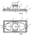
- Fig. 4 shows a side view of a loudspeaker.
- the loudspeaker consists of a magnet system 19, a basket 16, an upwardly flanged edge 17 and a snap-in device 8, 9. There is a seal 18 on the radiating surface of the loudspeaker.
- Fig. 5 shows a top view of the loudspeaker. As can be seen in FIG. 4, the seal 18 projects beyond the edge 17 of the loudspeaker. As a result, the speaker is clamped to the cover frame.
Landscapes
- Physics & Mathematics (AREA)
- Engineering & Computer Science (AREA)
- Acoustics & Sound (AREA)
- Signal Processing (AREA)
- Audible-Bandwidth Dynamoelectric Transducers Other Than Pickups (AREA)
Description
- Die Erfindung geht aus von einer Lautsprechereinheit gemäß dem Oberbegriff des Anspruchs 1. Eine derartige Lautsprechereinheit ist bekannt durch die US-A-3 575 370.
- Der Erfindung liegt die Aufgabe zugrunde, eine derartige Lautsprechereinheit so auszubilden, daß eine fertigungstechnisch vereinfachte Verbindung zwischen dem Rahmen und dem Lautsprecherkorb erreicht wird, die insbesondere bei der Massenproduktion von Fernsehgeräten vorteilhaft ist.
- Diese Aufgabe wird durch die im Anspruch 1 angegebene Erfindung gelöst. Vorteilhafte Weiterbildungen der Erfindung sind in den Unteransprüchen beschrieben.
- Es ist auch eine Lautsprechereinheit bekannt (EP-A-0 024 461), bei der Lautsprecherkorb zwischen zwei Teilen eingefaßt ist, die über eine Rastverbindung zusammengesetzt sind. Dabei ist jedoch der Lautsprecherkorb nicht über eine Rastverbindung unmittelbar an dem Rahmen befestigt und hat auch keine Elemente für eine formschlüssige Rastverbindung.
- Es ist auch eine Lautsprechereinheit bekannt (US-A-4 424 881), bei der eine Abdeckhaube über eine formschlüssige Rastverbindung an einen Basisteil befestigt ist, um eine leichte Austauschbarkeit der Abdeckhaube zu ermöglichen. Dabei handelt es sich jedoch nicht um die Befestigung eines Lautsprechers an dem Rahmen einer Lautsprechereinheit.
- Die Erfindung wird im folgenden anhand der Zeichnung an mehreren Ausführungsbeispielen erläutert. Darin zeigen
- Fig. 1 einen Lautsprecherkorb,
- Fig. 2 ein Ausführungsbeispiel für einen Rahmen mit federnden Elementen,
- Fig. 3 ein anderes Ausführungsbeispiel für einen Rahmen ohne federnde Elemente,
- Fig. 4 eine Seitenansicht und
- Fig. 5 eine Draufsicht auf den Lautsprecher.
- Fig. 1 zeigt einen Lautsprecherkorb 7 für seitliche und stirnseitige Montage an einem Rahmen. Für die seitliche Montage sind Bereiche aus konisch zum Rand des Lautsprecherkorbes 7 geöffneten Erhebungen 5 und Bereiche des Lautsprecherkorbes 7 aus länglichen konkaven Materialaussparungen 6 vorgesehen. Für die stirnseitige Montage des Lautsprecherkorbes 7 an einem Rahmen sind Vorsprünge 9 und ein beweglicher Vorsprung 8 vorgesehen. Der Vorsprung 9 ist an einer ersten Stirnseite des Lautsprecherkorbes 7 als Materialfortsetzung angebracht. Er hat die Form einer rechteckigen Zunge. Diesem Vorsprung 9 gegenüber, auf der anderen Stirnseite des Lautsprecherkorbes 7, befindet sich der bewegbare Vorsprung 8, der eine U-förmige Form aufweist und dessen dem Vorsprung 9 zugewandter erste Schenkel mit dem Lautsprecherkorb 7 verbunden ist. Dieser erste Schenkel weist zudem eine Stütze 13 auf. An dem anderen Schenkel des U-formigen Vorsprungs 8, der länger ausgebildet ist, befindet sich ein keilförmiger Ansatz 14, dessen Spitze sich am Ende des Schenkels und dessen verbreiterte Fläche sich in Höhe des Lautsprecherkorbes 7 befindet.
- Fig. 2 zeigt eine Lautsprechereinheit, bei der die Verbindungspunkte eines Rahmens 3 an den seitlichen Kanten des Lautsprecherkorbes 7 eingerastet sind. Dabei weist der Rahmen 3 bewegliche Vorsprünge 2, sogenannte Snap-In, und feste Vorsprünge 1 auf. In die konisch zum Rahmen hin geöffneten Erhebungen 5 ragen die festen Vorsprünge 1 des Rahmens 3. Beim Andrücken des Lautsprecherkorbes 7 an den Rahmen 3 hintergreifen die Vorsprünge 2 den Lautsprecherkorb 7 an den Aussparungen 6. Dadurch ergibt sich eine feste Verbindung zwischen Lautsprecherkorb 7 und Rahmen 3.
- Fig. 3 zeigt eine weitere Lautsprechereinheit, wobei die stirnseitigen Verbindungselemente Lautsprecher 7 und Rahmen 11 miteinander verbinden. Der zungenartige Vorsprung 9 des Lautsprecherkorbes 7 hintergreift beim Montieren die Aussparung 10 an der Stirnseite des Lautsprecherrahmens 11. Eine gleichartig aufgebaute Aussparung 10 ist ebenfalls an der gegenüberliegenden Stirnseite vorhanden. Beim Andrücken des Lautsprecherkorbes 7 an den Rahmen 11 hintergreift der bewegliche Vorsprung 8 mit der verbreiterten Fläche des keilförmigen Ansatzes 14 diese Aussparung 10. Der Rahmen 11 ist so aufgebaut, daß die montage des Lautsprecherkorbes 7 mit dem Rahmen 11 durch seitliche Führungsstege 15 erleichtert wird. Gleiches gilt auch für den Rahmen 3 mit Führungsstegen 12.
- Fig. 4 zeigt eine seitliche Ansicht eines Lautsprechers. Der Lautsprecher besteht aus einem Magnetsystem 19, einem Korb 16, einem nach oben umgebördelten Rand 17 und einer Snap-In-Vorrichtung 8, 9. An der Abstrahlfläche des Lautsprechers befindet sich eine Dichtung 18.
- Fig. 5 zeigt eine Draufsicht des Lautsprechers. Wie der Fig. 4 zu entnehmen ist, steht die Dichtung 18 über den Rand 17 des Lautsprechers hinaus. Dadurch wird ein Klemmen des Lautsprechers an dem Deckrahmen erreicht.
Claims (5)
Priority Applications (1)
| Application Number | Priority Date | Filing Date | Title |
|---|---|---|---|
| AT85100273T ATE45262T1 (de) | 1984-01-26 | 1985-01-12 | Lautsprechereinheit. |
Applications Claiming Priority (4)
| Application Number | Priority Date | Filing Date | Title |
|---|---|---|---|
| DE8402128U | 1984-01-26 | ||
| DE19848402128 DE8402128U1 (de) | 1984-01-26 | 1984-01-26 | Lautsprechereinheit |
| DE19848418098 DE8418098U1 (de) | 1984-06-15 | 1984-06-15 | Lautsprechereinheit |
| DE8418098U | 1984-06-15 |
Publications (3)
| Publication Number | Publication Date |
|---|---|
| EP0150744A2 EP0150744A2 (de) | 1985-08-07 |
| EP0150744A3 EP0150744A3 (en) | 1986-02-12 |
| EP0150744B1 true EP0150744B1 (de) | 1989-08-02 |
Family
ID=25949821
Family Applications (1)
| Application Number | Title | Priority Date | Filing Date |
|---|---|---|---|
| EP85100273A Expired EP0150744B1 (de) | 1984-01-26 | 1985-01-12 | Lautsprechereinheit |
Country Status (5)
| Country | Link |
|---|---|
| EP (1) | EP0150744B1 (de) |
| DE (1) | DE3572110D1 (de) |
| FI (1) | FI82582C (de) |
| HK (1) | HK991A (de) |
| SG (1) | SG99890G (de) |
Families Citing this family (4)
| Publication number | Priority date | Publication date | Assignee | Title |
|---|---|---|---|---|
| DE3534521A1 (de) * | 1985-09-27 | 1987-04-09 | Newek Neue Elektronik Werke Gm | Lautsprechereinheit |
| DE3682313D1 (de) * | 1985-04-11 | 1991-12-12 | Telefunken Fernseh & Rundfunk | Lautsprechereinheit. |
| DE3634269A1 (de) * | 1986-10-08 | 1988-04-21 | Electronic Werke Deutschland | Lautsprechereinheit |
| DE9210534U1 (de) * | 1992-08-06 | 1992-10-22 | Nokia (Deutschland) GmbH, 7530 Pforzheim | Lötösenplatte für Lautsprecher |
Family Cites Families (5)
| Publication number | Priority date | Publication date | Assignee | Title |
|---|---|---|---|---|
| US3575370A (en) * | 1969-08-29 | 1971-04-20 | Philco Ford Corp | Snap-in mounting for loudspeakers and the like |
| GB1336522A (en) * | 1971-05-17 | 1973-11-07 | Motorola Inc | Speaker mounting apparatus |
| JPS5233324U (de) * | 1975-09-01 | 1977-03-09 | ||
| EP0024461A1 (de) * | 1979-03-26 | 1981-03-11 | Schweizer, René - verstorben - gesetzlich vertreten durch Scheidegger, Franz | Lautsprecher-Anlage für Decken- und Wandmontage und Systemgehäuse für elektrische Apparate für Decken- und Wandmontage |
| US4424881A (en) * | 1982-02-17 | 1984-01-10 | Emhart Industries, Inc. | Speaker assembly |
-
1985
- 1985-01-12 EP EP85100273A patent/EP0150744B1/de not_active Expired
- 1985-01-12 DE DE8585100273T patent/DE3572110D1/de not_active Expired
- 1985-01-23 FI FI850290A patent/FI82582C/fi not_active IP Right Cessation
-
1990
- 1990-12-13 SG SG998/90A patent/SG99890G/en unknown
-
1991
- 1991-01-03 HK HK9/91A patent/HK991A/xx unknown
Also Published As
| Publication number | Publication date |
|---|---|
| DE3572110D1 (en) | 1989-09-07 |
| FI82582B (fi) | 1990-11-30 |
| HK991A (en) | 1991-01-11 |
| FI850290A0 (fi) | 1985-01-23 |
| EP0150744A2 (de) | 1985-08-07 |
| FI850290L (fi) | 1985-07-27 |
| SG99890G (en) | 1991-02-14 |
| FI82582C (fi) | 1991-03-11 |
| EP0150744A3 (en) | 1986-02-12 |
Similar Documents
| Publication | Publication Date | Title |
|---|---|---|
| DE4004385C2 (de) | Elektrischer Steckverbinder | |
| DE3311488C2 (de) | Überspannungsschutzvorrichtung zum Anbau an einen Anschlußverteiler | |
| DE69119684T2 (de) | Vorrichtung zur Montage und Befestigung von einzelnen Modulen auf einem Halterahmen | |
| DE60036250T2 (de) | Modularer Jack-Verbinder mit Filtereinsatz und Kontakt dafür | |
| DE4131504C2 (de) | Federelement für eine Baugruppe eines elektronischen Steuergeräts | |
| EP0412331B1 (de) | Vorrichtung zur elektrischen Verbindung von Abschirmungen mehrpoliger Stecker mit der Erdpotentialschicht einer Verdrahtungsplatte | |
| EP0766483A2 (de) | Erdungsbügel, insbesondere zur Verwendung in einer Anschlusseinrichtung für die Fernmelde- und Datentechnik | |
| DE4010906C2 (de) | Buchse mit Schalter | |
| DE3823951C2 (de) | Elektrische Leitungsklemme | |
| DE2845809A1 (de) | Daempfungsanordnung und gehaeuse fuer eine daempfungsanordnung | |
| EP0477663B1 (de) | Kontaktbauelement | |
| DE69304133T2 (de) | Anschluss eines Erdungsdrahtes an die Abschirmung eines elektrischen Verbinders | |
| DE29617895U1 (de) | Versorgungsbalken für die Intensivpflege | |
| DE8235283U1 (de) | Elektromagnetisches Relais | |
| DE29802727U1 (de) | Anschlußleiste und auf eine Anschlußleiste aufsteckbares Überspannungsschutzmagazin | |
| DE2618317C2 (de) | Adapter zur Verbindung elektromagnetischer Schaltgeräte mit gedruckten Leiterplatten | |
| DE2929382C2 (de) | Kippriegel-Verschlußbeschlag für Kipp-Schwenk-Fenster, -Türen o. dgl. | |
| EP0150744A2 (de) | Lautsprechereinheit | |
| DE8402128U1 (de) | Lautsprechereinheit | |
| EP0208129A2 (de) | Schutzgehäuse | |
| DE9402714U1 (de) | Baugruppenträger mit Profilleisten und mit Deckplatten | |
| DE9310630U1 (de) | An einer Montagefläche befestigtes elektrisches Gerät | |
| DE69403026T2 (de) | Teilnehmeranschlussvorrichtung | |
| DE19640847A1 (de) | Rechtwinkliger abgeschirmter elektrischer Verbinder | |
| DE69301519T2 (de) | Dreipoliges Schutzmodul mit Kurzschluss-Schmelzsicherung |
Legal Events
| Date | Code | Title | Description |
|---|---|---|---|
| PUAI | Public reference made under article 153(3) epc to a published international application that has entered the european phase |
Free format text: ORIGINAL CODE: 0009012 |
|
| AK | Designated contracting states |
Designated state(s): AT BE CH DE FR GB IT LI LU NL SE |
|
| PUAL | Search report despatched |
Free format text: ORIGINAL CODE: 0009013 |
|
| AK | Designated contracting states |
Designated state(s): AT BE CH DE FR GB IT LI LU NL SE |
|
| 17P | Request for examination filed |
Effective date: 19860716 |
|
| 17Q | First examination report despatched |
Effective date: 19871116 |
|
| GRAA | (expected) grant |
Free format text: ORIGINAL CODE: 0009210 |
|
| AK | Designated contracting states |
Kind code of ref document: B1 Designated state(s): AT BE CH DE FR GB IT LI LU NL SE |
|
| REF | Corresponds to: |
Ref document number: 45262 Country of ref document: AT Date of ref document: 19890815 Kind code of ref document: T |
|
| ITF | It: translation for a ep patent filed | ||
| GBT | Gb: translation of ep patent filed (gb section 77(6)(a)/1977) | ||
| REF | Corresponds to: |
Ref document number: 3572110 Country of ref document: DE Date of ref document: 19890907 |
|
| ET | Fr: translation filed | ||
| ITTA | It: last paid annual fee | ||
| PLBE | No opposition filed within time limit |
Free format text: ORIGINAL CODE: 0009261 |
|
| STAA | Information on the status of an ep patent application or granted ep patent |
Free format text: STATUS: NO OPPOSITION FILED WITHIN TIME LIMIT |
|
| 26N | No opposition filed | ||
| PGFP | Annual fee paid to national office [announced via postgrant information from national office to epo] |
Ref country code: LU Payment date: 19921217 Year of fee payment: 9 |
|
| PGFP | Annual fee paid to national office [announced via postgrant information from national office to epo] |
Ref country code: AT Payment date: 19930104 Year of fee payment: 9 |
|
| PGFP | Annual fee paid to national office [announced via postgrant information from national office to epo] |
Ref country code: SE Payment date: 19930127 Year of fee payment: 9 Ref country code: BE Payment date: 19930127 Year of fee payment: 9 |
|
| PGFP | Annual fee paid to national office [announced via postgrant information from national office to epo] |
Ref country code: NL Payment date: 19930131 Year of fee payment: 9 |
|
| PGFP | Annual fee paid to national office [announced via postgrant information from national office to epo] |
Ref country code: CH Payment date: 19930202 Year of fee payment: 9 |
|
| EPTA | Lu: last paid annual fee | ||
| PG25 | Lapsed in a contracting state [announced via postgrant information from national office to epo] |
Ref country code: LU Free format text: LAPSE BECAUSE OF NON-PAYMENT OF DUE FEES Effective date: 19940112 Ref country code: AT Effective date: 19940112 |
|
| PG25 | Lapsed in a contracting state [announced via postgrant information from national office to epo] |
Ref country code: SE Effective date: 19940113 |
|
| PG25 | Lapsed in a contracting state [announced via postgrant information from national office to epo] |
Ref country code: LI Effective date: 19940131 Ref country code: CH Effective date: 19940131 Ref country code: BE Effective date: 19940131 |
|
| BERE | Be: lapsed |
Owner name: TELEFUNKEN FERNSEH UND RUNDFUNK G.M.B.H. Effective date: 19940131 |
|
| PG25 | Lapsed in a contracting state [announced via postgrant information from national office to epo] |
Ref country code: NL Effective date: 19940801 |
|
| NLV4 | Nl: lapsed or anulled due to non-payment of the annual fee | ||
| REG | Reference to a national code |
Ref country code: CH Ref legal event code: PL |
|
| PGFP | Annual fee paid to national office [announced via postgrant information from national office to epo] |
Ref country code: GB Payment date: 19941207 Year of fee payment: 11 |
|
| PGFP | Annual fee paid to national office [announced via postgrant information from national office to epo] |
Ref country code: FR Payment date: 19950116 Year of fee payment: 11 |
|
| EUG | Se: european patent has lapsed |
Ref document number: 85100273.3 Effective date: 19940810 |
|
| PGFP | Annual fee paid to national office [announced via postgrant information from national office to epo] |
Ref country code: DE Payment date: 19950320 Year of fee payment: 11 |
|
| PG25 | Lapsed in a contracting state [announced via postgrant information from national office to epo] |
Ref country code: GB Effective date: 19960112 |
|
| GBPC | Gb: european patent ceased through non-payment of renewal fee |
Effective date: 19960112 |
|
| PG25 | Lapsed in a contracting state [announced via postgrant information from national office to epo] |
Ref country code: FR Effective date: 19960930 |
|
| PG25 | Lapsed in a contracting state [announced via postgrant information from national office to epo] |
Ref country code: DE Effective date: 19961001 |
|
| REG | Reference to a national code |
Ref country code: FR Ref legal event code: ST |