EP0149826B1 - Tabacco filter tip attaching apparatus - Google Patents
Tabacco filter tip attaching apparatus Download PDFInfo
- Publication number
- EP0149826B1 EP0149826B1 EP84115859A EP84115859A EP0149826B1 EP 0149826 B1 EP0149826 B1 EP 0149826B1 EP 84115859 A EP84115859 A EP 84115859A EP 84115859 A EP84115859 A EP 84115859A EP 0149826 B1 EP0149826 B1 EP 0149826B1
- Authority
- EP
- European Patent Office
- Prior art keywords
- tip
- filter tip
- filter
- paper
- feed
- Prior art date
- Legal status (The legal status is an assumption and is not a legal conclusion. Google has not performed a legal analysis and makes no representation as to the accuracy of the status listed.)
- Expired
Links
- 235000019504 cigarettes Nutrition 0.000 claims description 23
- 241000208125 Nicotiana Species 0.000 claims description 17
- 235000002637 Nicotiana tabacum Nutrition 0.000 claims description 17
- 238000005096 rolling process Methods 0.000 claims description 13
- 238000005520 cutting process Methods 0.000 claims description 11
- 238000010276 construction Methods 0.000 description 3
- 230000002950 deficient Effects 0.000 description 2
- 238000010586 diagram Methods 0.000 description 2
- 239000004925 Acrylic resin Substances 0.000 description 1
- 229920000178 Acrylic resin Polymers 0.000 description 1
- 244000061176 Nicotiana tabacum Species 0.000 description 1
- 230000010485 coping Effects 0.000 description 1
- 230000007547 defect Effects 0.000 description 1
- 238000001514 detection method Methods 0.000 description 1
- 238000007689 inspection Methods 0.000 description 1
- 238000004519 manufacturing process Methods 0.000 description 1
- 238000000034 method Methods 0.000 description 1
- 238000012544 monitoring process Methods 0.000 description 1
- 238000012856 packing Methods 0.000 description 1
- 230000004044 response Effects 0.000 description 1
Images


Classifications
-
- A—HUMAN NECESSITIES
- A24—TOBACCO; CIGARS; CIGARETTES; SIMULATED SMOKING DEVICES; SMOKERS' REQUISITES
- A24C—MACHINES FOR MAKING CIGARS OR CIGARETTES
- A24C5/00—Making cigarettes; Making tipping materials for, or attaching filters or mouthpieces to, cigars or cigarettes
- A24C5/14—Machines of the continuous-rod type
- A24C5/31—Machines of the continuous-rod type with special arrangements coming into operation during starting, slowing-down or breakdown of the machine, e.g. for diverting or breaking the continuous rod
-
- Y—GENERAL TAGGING OF NEW TECHNOLOGICAL DEVELOPMENTS; GENERAL TAGGING OF CROSS-SECTIONAL TECHNOLOGIES SPANNING OVER SEVERAL SECTIONS OF THE IPC; TECHNICAL SUBJECTS COVERED BY FORMER USPC CROSS-REFERENCE ART COLLECTIONS [XRACs] AND DIGESTS
- Y10—TECHNICAL SUBJECTS COVERED BY FORMER USPC
- Y10S—TECHNICAL SUBJECTS COVERED BY FORMER USPC CROSS-REFERENCE ART COLLECTIONS [XRACs] AND DIGESTS
- Y10S131/00—Tobacco
- Y10S131/91—Sensing or detecting malfunction in cigar or cigarette maker
Definitions
- the present invention relates to an apparatus for attaching a filter tip to cigarette of a predetermined length manufactured by a tobacco paper rolling machine.
- a filter tip sensor is adapted for detecting that the feed of the filter tip from said filter tip feed portion to said filter tip attaching portion is discontinued and a tip paper cutting sensor is provided for detecting a cutting accident of the tip paper during the feed from said tip paper feed portion to said filter tip attaching portion. Finally, a roll diameter sensor is provided for detecting that the diameter of the tip paper roll in said tip paper feed portion has become smaller than a predetermined value.
- GB-A-1 442 751 discloses a similar cigarette making machine which is covered by a cover being provided with openable doors in positions corresponding respectively to said filter tip feed portion, filter tip attaching portion and the tip paper feed portion.
- the present invention has been accomplished in order to eliminate the above-mentioned drawbacks of the prior art, and it is the object thereof to provide a tobacco filter tip attaching apparatus in which doors each adapted to be opened and closed by operation of a power source are provided in positions corresponding to various portions of the apparatus, and the doors of which should be opened is judged on the basis of outputs of sensors disposed in various portions of the apparatus, and the power source corresponding to that door is operated in accordance with the result of the judgement to open automatically the door corresponding to the portion of the apparatus where the required work must be done, whereby the manual door opening by the operator is eliminated to improve the working efficiency.
- Fig. 1 is a schematic front view of a tobacco filter tip attaching apparatus to which the invention is applied.
- This tobacco filter tip attaching apparatus indicated at A is connected to a tobacco paper rolling machine B which rolls shredded tobacco leaves with a rolling paper, and cigarettes of a predetermined length manufactured by the tobacco paper rolling machine B are fed successively to the apparatus A.
- the numeral 10 denotes a tobacco filter tip feed portion.
- the filter tip feed portion 10 comprises a hopper 10a which contains a large number of filter plugs each having a length three times as large as the filter tip, a cutter drum 10b for cutting a filter plug 11 having such a length as shown in Fig. 3a received one by one from the hopper 10a into filter tips 11 a each having a length one-third of the filter plug 11 as shown in Fig. 3b, a grading drum 10c for shifting in relative position the filter tips 11a trisected in the cutter drum 10b, as shown in Fig. 3c, an aligning drum 10d aligning as shown in Fig. 3d the three filter tips which have been shifted in relative position by the grading drum 10c, and a delivery drum 10e for delivering one by one the thus-aligned filter tips 11a.
- the numeral 12 denotes a cigarette feed portion.
- the cigarette feed portion 12 comprises a receiving drum 12a which receives in such a zigzag form as shown in Fig. 4a cigarettes 13 fed from the tobacco paper rolling machine B, and a grading drum 12b for rearranging the cigarettes received by the receiving drum 12a into a spaced form to an extent permitting interposition of a single filter tip as shown in Fig. 4b and delivering the same.
- the numeral 14 denotes a filter tip attaching portion.
- the filter tip attaching portion 14 comprises a hopper drum 14a which receives two cigarettes 13 spaced from each other as shown in Fig. 4b from the grading drum 12b in the cigarette feed portion 12 and which receives between the two cigarettes 13 the filter tip 11a a delivered from the delivery drum 10e in the filter tip feed portion 10, as shown in Fig. 5a, a transfer drum 14b which receives a predetermined length of a tip paper 15 with paste fed from a later-described tip paper feed portion and also receives the cigarettes 13 and filter tip 11a from the hopper drum 14a in such a state as shown in Fig. 5b and transfers them to the next rolling step, and a rolling drum 4c for rolling and pasting the tip paper 15 onto the filter tip 11a a and the portions of the cigarettes 13 adjacent thereto as shown in Fig. 5c.
- the numeral 16 denotes an inspection drum for checking the pasted state of the tip paper 15 rolled onto the two cigarettes 13 and filter tip 11a a in the filter tip attaching portion 14 and detecting a defect.
- the numeral 18 denotes a cutter drum for cutting the cigarette with filter tip obtained in the filter tip attaching portion 14 and comprising two cigarettes 13 and one filter tip 11a attached in common thereto, at the center of the tip paper 15 to obtain two regular cigarettes 19 with filter tip as shown in Fig. 6a.
- the numerals 20 and 22 denote an aligning drum and an inverting drum, respectively.
- the two cigarettes 10 with filter tip which are in such a state as shown in Fig. 6a are inverted and aligned into such a state as shown in Fig. 6b and then delivered successively onto a belt conveyor 23, which in turn transfers the cigarettes 19 with filter tip to the next packing step.
- the numeral 24 denotes a tip paper feed portion for feeding the tip paper of a predetermined length with paste to the filter tip attaching portion 14.
- the tip paper feed portion has a pair of tip paper roll loading bobbins 24a which are rotatably supported by a rotation support frame 24b.
- tip paper is delivered from a tip paper roll 25 loaded on the left-hand bobbin 24a.
- the support frame 24b is rotated 180 degrees in the direction of arrow as illustrated to move the roll 25 to the right-hand bobbin position.
- the numeral 28 denotes a pasting portion for pasting one side of tip paper fed to the filter tip attaching portion 14; the numeral 30 denotes a cutter portion for cutting the pasted tip paper into a predetermined length; and the numeral 32 denotes a suction roller for sucking the pasted tip paper 15 of a predetermined length and feeding it onto transfer drum 14b.
- One of such states is a state in which the feed of filter plug from the filter plug feed portion 10 stops due to clogging of the outlet portion of the hopper 10a with filter plugs and therefore the feed of filter tip 11a a to the filter tip attaching portion 14 is no longer continued.
- the apparatus will continue to make defective products during stoppage of the feed of filter tip, so it is necessary to immediately stop the operation of the apparatus temporarily and remove the filter plugs which cause clogging.
- a plug clogging sensor 40 which detects stoppage of feed of, for example, two consecutive filter plugs from the hopper 10a and thereby detects a plug clogging.
- a limit switch having a movable piece 40a of a shape which permits a simultaneous contact of the movable piece with filter plugs in two adjacent plug receiving recesses 10b' formed in the surface of the cutter drum 10b as shown in Fig. 7.
- the diameter of the tip paper roll 25 located on the left-hand bobbin 24a of the tip paper feed portion 24 becomes smaller than the predetermined value, it is necessary to move the roll reduced in diameter to the right-hand side, load a new tip paper roll onto the left-hand side bobbin and perform a predetermined setting work for allowing the leading end of a new roll to be automatically connected to the terminal end of the tip paper of the reduced-diameter roll when the latter has run out.
- a roll diameter sensor 44 for detecting that the diameter of the left-hand tip paper roll has become smaller than the predetermined value.
- a limit switch having a movable contact lever 44a adapted to move along the outer periphery of the tip paper roll 25 loaded on the left-hand bobbin 24a, as shown in Fig. 1, or a rotary encoder adapted to rotate together with the bobbin 24a to detect a number of revolutions of the bobbins exceeding a predetermined value.
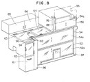
- the illustrated cover is provided with first and second upwardly hinged doors 52 and 54 in positions corresponding to the right and left sides of the filter tip attaching portion 14 and the tip paper feed portion 24 located below them. Further, a third upwardly hinged door 56 is provided in a position corresponding to the filter tip feed portion 10 which is located above the filter tip attaching portion 14.
- the doors 52 to 56 are fitted, for example, acrylic resin plates to constitute see-through windows 52a to 56a so that the corresponding inside portions can be seen from the outside in a closed state of the doors.
- the numerals 61 to 65 denote manually opened and closed doors. Since these doors have no direct bearing on the present invention, explanation thereon is here omitted.
- Fig. 9 is a top view illustrating drive cylinders 72 and 74 as drive sources provided correspondingly to the doors 52 and 54.
- To movable pieces 72a and 74a of the cylinders 72 and 74 are connected connecting arms 52b and 54b respectively which extend from one side edges of the doors 52 and 54.
- the connecting arms 52b and 54b are vertically guided through linear bearings 82a and 84a by guide bars 82 and 84 which are erected along the drive cylinders 72 and 74.
- the other side edges of the doors 52 and 54 are also partially extended as extensions 52c and 54c and vertically guided by guide bars 83 and 85 through linear bearings 83a and 85a.
- the cylinders 72, 74 and the guide bars 82, 84 are masked with a pillar-like decorative cover 86, while the guide bars 83 and 85 are masked with a plate-like decorative cover 87.
- an extension from its left side edge is connected to a movable piece of the drive cylinder 76 housed in a decorative cover 88 and is guided by a guide bar (not shown), and an extension from its right side edge is also guided by another guide bar (not shown).
- the doors 52, 54 and 56 are moved vertically in the directions of arrows as illustrated by the operation of the drive cylinders 72, 74 and 76 corresponding respectively to those doors.
- pillar-like decorative cover 86 On the upper surface of the pillar-like decorative cover 86 are provided three manually operating button switches 92, 94 and 96 for operating the drive cylinders corresponding to the doors to open and close the doors manually each independently, as well as a closing button switch 97 for simultaneously closing all of the doors opened automatically.
- Fig. 11 illustrates a control circuit which produces signals for actuating the cylinders 72-76 corresponding respectively to the doors 52-56 in accordance with signals provided from the sensors 40-44 and operating button switches 92-97. Operation of this circuit will be described below.
- an R-S flip flop (FF) 101 is set in response to the leading edge of the signal and its output Q goes from L to H level.
- the outputs of OR gates 105 and 106 become H level, and the cylinders 76 and 74 are actuated in the direction of opening the doors 52 and 54, so the doors 52 and 54 are simultaneously opened automatically. Therefore, the operator can immediately judge the cause of discontinued feed of filter tips and replenish filter tips into the hopper 10a if there are not tips therein, or remove filter tips if the tips are the cause of clogging of the passage.
- the apparatus When the apparatus is restarted after removal of such obstacle, it is operated at a low speed, so whether filter chips are fed smoothly or not is checked at this stage, and if there is no problem, the high-speed operating button switch 97 is pushed, whereby the FF 101 is reset to produce an L-level signal at its output terminal Q.
- the outputs of the OR gates 105 and 106 which have been H level become L level and the cylinders 76 and 74 revert to the original closed state, so the doors 56 and 54 are closed simultaneously.
- the R-S FF is set to produce an H-level signal.
- the outputs of the OR gates 104 and 107 become H level and the cylinder 72 is actuated in the opening direction by the output of the OR gate 107, so the door 52 is opened automatically.
- the work of resetting the fore end oftip paperto the predetermined position can be done at once. If the operation is restarted after this setting work and then after a while the high-speed operating button switch 97 is pushed, the FF 102 is reset and its output Q becomes L level, whereby the cylinder 72 is operated in the direction of closing the door 52.
- the R-S FF is set to produce an H-level signal at its output terminal Q.
- the outputs of the OR gates 104 and 107 become H level and the cylinder 72 adapted to be controlled by the output of the OR gate 107 is operated in the opening direction, so the door 52 is opened automatically.
- the operator can immediately perform the work of rotating the support frame 24b so that the tip paper roll reduced in diameter shifts to the right-hand side, then loading a new tip paper roll in the left-hand position and subsequently performing the setting for automatic connection between tip papers.
- the present invention since the whole of the machine is covered, it is possible to greatly reduce noise induced by the filter tip attaching apparatus during high-speed operation. Besides, since the doors corresponding to various portions of the apparatus which require operations by the operator for coping with clogging caused by filter tips, cutting of tip paper and automatic connection between tip papers, can be opened automatically, the troublesome work of judging the door to be opened and opening it manually during operation is no longer necessary, thus greatly improving the working efficiency.
Landscapes
- Manufacturing Of Cigar And Cigarette Tobacco (AREA)
Applications Claiming Priority (2)
| Application Number | Priority Date | Filing Date | Title |
|---|---|---|---|
| JP244868/83 | 1983-12-27 | ||
| JP58244868A JPS60141273A (ja) | 1983-12-27 | 1983-12-27 | たばこフイルタチツプ取付装置 |
Publications (3)
| Publication Number | Publication Date |
|---|---|
| EP0149826A2 EP0149826A2 (en) | 1985-07-31 |
| EP0149826A3 EP0149826A3 (en) | 1985-08-14 |
| EP0149826B1 true EP0149826B1 (en) | 1988-03-16 |
Family
ID=17125188
Family Applications (1)
| Application Number | Title | Priority Date | Filing Date |
|---|---|---|---|
| EP84115859A Expired EP0149826B1 (en) | 1983-12-27 | 1984-12-19 | Tabacco filter tip attaching apparatus |
Country Status (4)
| Country | Link |
|---|---|
| US (1) | US4619277A (https=) |
| EP (1) | EP0149826B1 (https=) |
| JP (1) | JPS60141273A (https=) |
| DE (1) | DE3469845D1 (https=) |
Families Citing this family (3)
| Publication number | Priority date | Publication date | Assignee | Title |
|---|---|---|---|---|
| US4724429A (en) * | 1986-03-07 | 1988-02-09 | Celanese Corporation | Diagnostic and control system for cigarette filter rod making machine |
| JP3702071B2 (ja) * | 1997-06-16 | 2005-10-05 | 三洋電機株式会社 | 飲料抽出装置におけるペーパーフィルタ送出装置 |
| EP1415553A1 (de) * | 2002-10-31 | 2004-05-06 | Hauni Maschinenbau AG | Verriegelung von Verschutzungen |
Family Cites Families (9)
| Publication number | Priority date | Publication date | Assignee | Title |
|---|---|---|---|---|
| FR1313677A (fr) * | 1962-02-06 | 1962-12-28 | Ministere De L Ind Alimentaire | Machine pour la fabrication de filtres à cigarettes |
| DE1915339A1 (de) * | 1969-03-26 | 1970-10-08 | Hauni Werke Koerber & Co Kg | Verfahren zum Seuern der Materialzufuhr zu einer stabfoermige Tabakartikel od.dgl. erzeugenden oder verarbeitenden Maschine |
| DE2013078A1 (de) * | 1970-03-19 | 1971-09-30 | Hauni Werke Korber & Co KG, 2050 Hamburg | Verfahren und Vorrichtung zum Über wachen der Funktion von tabakverarbeitenden Maschinen |
| GB1442751A (en) * | 1972-05-05 | 1976-07-14 | Molins Ltd | Cigarette making machines |
| GB1526394A (en) * | 1974-09-17 | 1978-09-27 | Molins Ltd | Manufacture of filter-tipped cigarettes |
| GB1526395A (en) * | 1974-11-15 | 1978-09-27 | Molins Ltd | Manufacture of filter-tipped cigarettes |
| DE2505998A1 (de) * | 1975-02-13 | 1976-08-26 | Hauni Werke Koerber & Co Kg | Vorrichtung zum entnehmen von stabfoermigen artikeln der tabakverarbeitenden industrie aus einem vorrat |
| IT1195041B (it) * | 1980-07-11 | 1988-09-28 | Hauni Werke Koerber & Co Kg | Procedimento e dispositivo per il controllo del funzionamento di dispositivi di controllo di una macchina per fabbricare articoli da fumo a forma di bastoncini |
| IT1166509B (it) * | 1982-06-01 | 1987-05-06 | British American Tobacco Co | Perfezionamenti relativi a macchine per la fabbricazione di sigarette |
-
1983
- 1983-12-27 JP JP58244868A patent/JPS60141273A/ja active Granted
-
1984
- 1984-12-19 DE DE8484115859T patent/DE3469845D1/de not_active Expired
- 1984-12-19 EP EP84115859A patent/EP0149826B1/en not_active Expired
- 1984-12-27 US US06/686,867 patent/US4619277A/en not_active Expired - Lifetime
Also Published As
| Publication number | Publication date |
|---|---|
| JPS625588B2 (https=) | 1987-02-05 |
| US4619277A (en) | 1986-10-28 |
| EP0149826A2 (en) | 1985-07-31 |
| EP0149826A3 (en) | 1985-08-14 |
| DE3469845D1 (en) | 1988-04-21 |
| JPS60141273A (ja) | 1985-07-26 |
Similar Documents
| Publication | Publication Date | Title |
|---|---|---|
| US5279195A (en) | Apparatus for continuously transporting, separating, and changing the path of webs | |
| JPH07165212A (ja) | 包装方法および装置 | |
| US5133173A (en) | Method and equipment for wrapping groups of packets | |
| US5101701A (en) | Method of changing strip material on a manufacturing machine | |
| EP0149826B1 (en) | Tabacco filter tip attaching apparatus | |
| EP0633210A1 (en) | Method and device for changing strip material on a production machine | |
| JPS629498B2 (https=) | ||
| JPH08103976A (ja) | 自動製函機における不良品排出装置 | |
| EP0569034B1 (en) | Device for guiding the travel of a tobacco rod in a cigarette manufacturing apparatus | |
| US6971979B1 (en) | Folded box gluing machine for producing folded boxes from blanks | |
| EP1300088B1 (en) | A cigarette maker outfeed unit | |
| US4437370A (en) | Method for the operation of a cross-cutting apparatus | |
| EP0150467B1 (en) | Tobacco manufacturing machine | |
| GB2082439A (en) | A cigarette rod-breaking device | |
| JPS6283880A (ja) | シガレツト製造機の巻たばこ印刷位置調整装置 | |
| US4120741A (en) | Carton sealing strip applicator | |
| JPH01145968A (ja) | 帯状材の搬送位置決め装置 | |
| JP2753600B1 (ja) | 製箱機の不良品識別装置 | |
| US5738486A (en) | Apparatus for unloading blocks of blanks that are stacked on pallets, with separators being interposed between the blocks | |
| JP3857185B2 (ja) | 折曲加工装置 | |
| JP3886602B2 (ja) | 結束体切断回収装置および方法 | |
| JP3293864B2 (ja) | 硬貨処理機 | |
| KR200392544Y1 (ko) | 골판지 제조기의 불량품 제거장치 | |
| JPH0118320Y2 (https=) | ||
| JPH08150510A (ja) | ストリップのセンタリング方法および装置 |
Legal Events
| Date | Code | Title | Description |
|---|---|---|---|
| PUAI | Public reference made under article 153(3) epc to a published international application that has entered the european phase |
Free format text: ORIGINAL CODE: 0009012 |
|
| PUAL | Search report despatched |
Free format text: ORIGINAL CODE: 0009013 |
|
| AK | Designated contracting states |
Designated state(s): DE GB IT |
|
| AK | Designated contracting states |
Designated state(s): DE GB IT |
|
| 17P | Request for examination filed |
Effective date: 19850822 |
|
| RAP1 | Party data changed (applicant data changed or rights of an application transferred) |
Owner name: JAPAN TOBACCO INC. |
|
| 17Q | First examination report despatched |
Effective date: 19860904 |
|
| GRAA | (expected) grant |
Free format text: ORIGINAL CODE: 0009210 |
|
| ITF | It: translation for a ep patent filed | ||
| AK | Designated contracting states |
Kind code of ref document: B1 Designated state(s): DE GB IT |
|
| REF | Corresponds to: |
Ref document number: 3469845 Country of ref document: DE Date of ref document: 19880421 |
|
| PLBE | No opposition filed within time limit |
Free format text: ORIGINAL CODE: 0009261 |
|
| STAA | Information on the status of an ep patent application or granted ep patent |
Free format text: STATUS: NO OPPOSITION FILED WITHIN TIME LIMIT |
|
| 26N | No opposition filed | ||
| ITTA | It: last paid annual fee | ||
| PGFP | Annual fee paid to national office [announced via postgrant information from national office to epo] |
Ref country code: GB Payment date: 19991122 Year of fee payment: 16 |
|
| PGFP | Annual fee paid to national office [announced via postgrant information from national office to epo] |
Ref country code: DE Payment date: 19991230 Year of fee payment: 16 |
|
| PG25 | Lapsed in a contracting state [announced via postgrant information from national office to epo] |
Ref country code: GB Free format text: LAPSE BECAUSE OF NON-PAYMENT OF DUE FEES Effective date: 20001219 |
|
| GBPC | Gb: european patent ceased through non-payment of renewal fee |
Effective date: 20001219 |
|
| PG25 | Lapsed in a contracting state [announced via postgrant information from national office to epo] |
Ref country code: DE Free format text: LAPSE BECAUSE OF NON-PAYMENT OF DUE FEES Effective date: 20011002 |