EP0148151A2 - Bandage pneumatique, en particulier pneumatique radial pour poids-lourds - Google Patents
Bandage pneumatique, en particulier pneumatique radial pour poids-lourds Download PDFInfo
- Publication number
- EP0148151A2 EP0148151A2 EP84890223A EP84890223A EP0148151A2 EP 0148151 A2 EP0148151 A2 EP 0148151A2 EP 84890223 A EP84890223 A EP 84890223A EP 84890223 A EP84890223 A EP 84890223A EP 0148151 A2 EP0148151 A2 EP 0148151A2
- Authority
- EP
- European Patent Office
- Prior art keywords
- tread
- grooves
- section
- groove
- pneumatic vehicle
- Prior art date
- Legal status (The legal status is an assumption and is not a legal conclusion. Google has not performed a legal analysis and makes no representation as to the accuracy of the status listed.)
- Granted
Links
- 238000005299 abrasion Methods 0.000 description 6
- 230000002349 favourable effect Effects 0.000 description 6
- 239000004575 stone Substances 0.000 description 3
- 230000015572 biosynthetic process Effects 0.000 description 1
Images
Classifications
-
- B—PERFORMING OPERATIONS; TRANSPORTING
- B60—VEHICLES IN GENERAL
- B60C—VEHICLE TYRES; TYRE INFLATION; TYRE CHANGING; CONNECTING VALVES TO INFLATABLE ELASTIC BODIES IN GENERAL; DEVICES OR ARRANGEMENTS RELATED TO TYRES
- B60C11/00—Tyre tread bands; Tread patterns; Anti-skid inserts
- B60C11/03—Tread patterns
- B60C11/0306—Patterns comprising block rows or discontinuous ribs
- B60C11/0309—Patterns comprising block rows or discontinuous ribs further characterised by the groove cross-section
-
- B—PERFORMING OPERATIONS; TRANSPORTING
- B60—VEHICLES IN GENERAL
- B60C—VEHICLE TYRES; TYRE INFLATION; TYRE CHANGING; CONNECTING VALVES TO INFLATABLE ELASTIC BODIES IN GENERAL; DEVICES OR ARRANGEMENTS RELATED TO TYRES
- B60C11/00—Tyre tread bands; Tread patterns; Anti-skid inserts
- B60C11/03—Tread patterns
- B60C11/04—Tread patterns in which the raised area of the pattern consists only of continuous circumferential ribs, e.g. zig-zag
- B60C11/042—Tread patterns in which the raised area of the pattern consists only of continuous circumferential ribs, e.g. zig-zag further characterised by the groove cross-section
- B60C11/045—Tread patterns in which the raised area of the pattern consists only of continuous circumferential ribs, e.g. zig-zag further characterised by the groove cross-section the groove walls having a three-dimensional shape
-
- Y—GENERAL TAGGING OF NEW TECHNOLOGICAL DEVELOPMENTS; GENERAL TAGGING OF CROSS-SECTIONAL TECHNOLOGIES SPANNING OVER SEVERAL SECTIONS OF THE IPC; TECHNICAL SUBJECTS COVERED BY FORMER USPC CROSS-REFERENCE ART COLLECTIONS [XRACs] AND DIGESTS
- Y10—TECHNICAL SUBJECTS COVERED BY FORMER USPC
- Y10S—TECHNICAL SUBJECTS COVERED BY FORMER USPC CROSS-REFERENCE ART COLLECTIONS [XRACs] AND DIGESTS
- Y10S152/00—Resilient tires and wheels
- Y10S152/90—Tread pattern having no blocks and having circumferential ribs defined by zig-zag circumferential grooves
Definitions
- the invention relates to a pneumatic vehicle tire, in particular a radial tire for trucks, the tread of which has ribs running in the circumferential direction and separated from one another by zigzag-shaped grooves, the cross section of the grooves narrowing towards the groove base.
- Radial tires for trucks are usually provided with a tread which is divided into a certain number of ribs in the transverse direction by zigzag-shaped grooves running in the circumferential direction. It is also common practice to give the groove side walls a certain slope so that the groove narrows towards the groove bottom. The purpose of this measure is to promote the repulsion of foreign bodies, in particular stones, while driving. Hiebei proposes, for example, in US Pat. No. 2,604,920 to arrange the groove side walls at a constant angle to the vertical on the running surface. In a further known tire (AT-PS 309.250), the side walls of the grooves have an inclination which changes in the circumferential direction in a helical manner instead of a constant inclination.
- This design of the profile has a favorable effect on wear after a longer running time and on a straight route.
- the repulsion of foreign bodies is little favored by this profile when driving. This would require a larger opening angle of the groove, which, however, reduces the positive driving surface.
- moderate traction is to be expected in this known design and also in other known designs due to the same zigzag guide and the even design of the groove side walls.
- the invention is therefore based on the object of designing a pneumatic vehicle tire of the type mentioned at the outset in such a way that jamming of foreign bodies in the grooves in the tread is effectively prevented whose tread is subject to uniform wear even after a long running time, and that there are particularly favorable properties of the tread in relation to traction and straight running stability.
- the object is achieved according to the invention in that preferably the zigzag grooves running within the outer notes are viewed in cross-section and in the area between the angular areas, each having a perpendicular or almost perpendicular to the tread and opposite this having a double angled side wall, which side walls are provided alternately in successive sections of each zigzag-shaped groove, and that recessed corner areas are formed in the projecting angular areas and attached in the recessed angular areas.
- a groove cross section is therefore proposed in particular between the angular ranges of the grooves, which effectively prevents foreign bodies from being trapped, while at the same time the positive running surface of the tread can be kept optimally large. Due to the alternating sequence of angled and almost vertical side walls and the provision of patch or recessed corners in the angular areas, a uniform abrasion of the tread is achieved. In particular, the formation of so-called freewheel grooves is prevented, the rib edges being affected first in the region of the angles protruding into the grooves.
- the pronounced structuring in particular in connection with the arrangement of these grooves in the central area of the tread, has a particularly favorable effect on the traction; in particular, the profile also has a better grip on snow compared to known tires with grooves running in a zigzag shape.
- Favorable results with regard to straight-line stability and steering accuracy are also achieved with the profile according to the invention.
- the double-angled side wall, according to the invention viewed in cross-section and in the area between the angular areas, is formed by two sections which run essentially perpendicular to the tread and are connected by an oblique flank.
- this makes it possible to arrange the flank at such a flat angle that the repulsion of stones and other foreign bodies is guaranteed in any case.
- hiebei has an angle of 20 cL 0 to 60 °, preferably 40 °, proved between a perpendicular to the tread and the sloping edge. This angle will be chosen depending on the groove depth, which depends on the type of tire.
- a particularly uniform wear of the tread over the first section of the stepped side wall is achieved according to the invention in that viewed from the top of the tread, the first section of the patched or recessed corner areas according to the first section of the side walls, preferably running essentially perpendicular to the tread , is trained.
- each attached or recessed corner region has at its first section two inclined regions both in the direction of the groove base and in the circumferential direction of the tread, which are essentially triangular in shape and include an angle with one another in the direction of the groove base converge.
- the grooves arranged within the outer grooves are of essentially the same width, and that the outer grooves are narrower and preferably have a width which is approximately a quarter of the width of the inner grooves.
- the abrasion to be expected in the shoulder area is kept low and uniform in that the shoulder straps, measured in each case from the outermost of the central grooves, have a width which is approximately a quarter of the width of the tread.
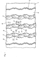
- FIG. 1 shows a plan view of a part of the tread of the pneumatic vehicle tire according to the invention
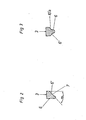
- FIG. 2 shows a groove of the tread in section along the line II-II in FIG. 1
- FIG. 3 shows the groove in section along the line III-III in FIG Fig. L.
- the tread 1 shown in the drawing figures is intended for a pneumatic pneumatic tire of a truck.
- the tread 1 is divided into ribs 8 in the transverse direction by five circumferential grooves with a zigzag course.
- the two outer grooves 2 are narrow, the three middle grooves 3 are wide.
- the grooves 2, 3 are composed of sections 4, 5 which are inclined alternately in one and the other direction and whose angle of inclination to the circumferential direction of the tread 1 is approximately 25 °.
- the successive sections 4, 5 of each wide groove 3 have side walls 6, 6 'in the area between the angular areas separating the sections 4, 5, the course and arrangement of which can be seen in particular from FIGS. 1 and 2.
- the one side wall 6 runs essentially perpendicular to the tread 1 to almost the groove base
- the opposite side wall 6 ' is angled twice and initially has a section which also runs essentially perpendicular to the tread 1 and is adjoined by an obliquely running flank 7, to which a further section, essentially perpendicular to the tread 1, connects in the direction of the groove base.
- the angle of inclination ⁇ of the flank 7 to the perpendicular to the tread 1 is approximately 45 ° in the present exemplary embodiment.
- the area delimiting a rib 8 is alternately formed by an almost vertical side wall 6 and a double-angled side wall 6 '.
- a recessed corner area 9 is formed, in the area of the recessed angular areas an attached corner area 9 'is formed. How especially out
- each corner region 9, 9 'then has, as can be seen in particular from FIG. 1, two essentially triangular regions 10a, 10b, 10'a, 10'b which run obliquely both in the direction of the groove base and the circumferential direction of the tread 1 on.
- the attached corner areas 9 protrude enclosing an angle, in the case of the recessed corner areas 9 'they are arranged in a correspondingly recessed manner.
- the areas 10a 10B, 10'a and 10'b are designed in such a way that they converge in the direction of the groove base, preferably up to the second, essentially perpendicular section of the side wall 6 '. This ensures a uniform profile of the groove sidewalls down to the groove base, which means that particularly favorable results with regard to traction behavior and abrasion can be achieved over the entire life of the tire. As is known per se, non-uniform wear would be most pronounced in the rib angles protruding into the grooves.
- the design of the side walls 6, 6 'according to the invention also ensures that an optimal stone ejection is ensured, while at the same time the positive running surface of the tread 1 can be kept as large as possible.
- the three central grooves 3 are of essentially the same width and the width of the two outer grooves 2 is approximately a quarter the width of the central grooves 3.
- the width of the shoulder straps, measured from the outermost of the central grooves 3 is approximately a quarter of the width of the tread 1.
- the invention is not restricted to the exemplary embodiment shown. It is thus possible in particular to vary the inclination of the flank of the double angled side wall, an angle in the range from 20 ° to 60 ° being proposed, depending on the groove depth or type of tire. In this context, it is also advantageous to arrange the first section of the angled side wall at an angle to the perpendicular to the running surface.
Landscapes
- Engineering & Computer Science (AREA)
- Mechanical Engineering (AREA)
- Tires In General (AREA)
- Steroid Compounds (AREA)
- Reinforced Plastic Materials (AREA)
Applications Claiming Priority (2)
| Application Number | Priority Date | Filing Date | Title |
|---|---|---|---|
| AT4505/83 | 1983-12-23 | ||
| AT0450583A AT379990B (de) | 1983-12-23 | 1983-12-23 | Laufflaeche fuer fahrzeugluftreifen, insbesondere fuer radialreifen fuer lastkraftwagen |
Publications (3)
| Publication Number | Publication Date |
|---|---|
| EP0148151A2 true EP0148151A2 (fr) | 1985-07-10 |
| EP0148151A3 EP0148151A3 (en) | 1986-05-14 |
| EP0148151B1 EP0148151B1 (fr) | 1988-11-09 |
Family
ID=3564894
Family Applications (1)
| Application Number | Title | Priority Date | Filing Date |
|---|---|---|---|
| EP84890223A Expired EP0148151B1 (fr) | 1983-12-23 | 1984-11-21 | Bandage pneumatique, en particulier pneumatique radial pour poids-lourds |
Country Status (6)
| Country | Link |
|---|---|
| US (1) | US4630661A (fr) |
| EP (1) | EP0148151B1 (fr) |
| AT (2) | AT379990B (fr) |
| DE (1) | DE3475056D1 (fr) |
| HU (1) | HU194096B (fr) |
| YU (1) | YU46599B (fr) |
Cited By (3)
| Publication number | Priority date | Publication date | Assignee | Title |
|---|---|---|---|---|
| EP0189199A2 (fr) * | 1985-01-25 | 1986-07-30 | Continental Aktiengesellschaft | Bandage pneumatique pour véhicules |
| DE102006052740B4 (de) * | 2005-11-09 | 2009-03-12 | Toyo Tire & Rubber Co., Ltd., Osaka-shi | Luftreifen |
| WO2016091411A1 (fr) * | 2014-12-11 | 2016-06-16 | Continental Reifen Deutschland Gmbh | Pneumatique de véhicule |
Families Citing this family (13)
| Publication number | Priority date | Publication date | Assignee | Title |
|---|---|---|---|---|
| JPS6192902A (ja) * | 1984-10-13 | 1986-05-10 | Sumitomo Rubber Ind Ltd | 重荷重用空気入りラジアルタイヤ |
| US5154216A (en) * | 1990-01-05 | 1992-10-13 | Sumitomo Rubber Industries, Ltd. | Radial tire for heavy duty vehicles |
| DE4107916A1 (de) * | 1991-03-12 | 1992-09-17 | Continental Ag | Fahrzeugreifen mit wellenfoermigen laengsrillen |
| USD381942S (en) * | 1995-10-31 | 1997-08-05 | The Goodyear Tire & Rubber Company | Tire tread |
| USD388031S (en) * | 1996-01-25 | 1997-12-23 | The Goodyear Tire & Rubber Company | Tire tread |
| USD382519S (en) * | 1996-02-14 | 1997-08-19 | The Goodyear Tire & Rubber Company | Tire tread |
| US6415835B1 (en) | 2000-06-08 | 2002-07-09 | The Goodyear Tire & Rubber Company | Pneumatic tire tread having groove with peaks and valleys |
| US7597127B2 (en) * | 2005-12-30 | 2009-10-06 | Continental Ag | Tire with tread including circumferential grooves having generally sinusoidal contour |
| US9278582B2 (en) | 2010-12-21 | 2016-03-08 | Bridgestone Americas Tire Operations, Llc | Tire tread having developing grooves |
| JP5403028B2 (ja) * | 2010-12-27 | 2014-01-29 | 横浜ゴム株式会社 | 空気入りタイヤ |
| IT1404060B1 (it) * | 2011-02-14 | 2013-11-08 | Bridgestone Corp | Striscia di battistrada con scanalature asimmetriche per ridurre la ritenzione di detriti |
| BR112016010541B1 (pt) | 2013-11-12 | 2021-03-09 | Cooper Tire & Rubber Company | banda de rodagem de pneu incluindo bordos denteados em bolsos recuados de parede lateral de ranhura |
| JP2017024687A (ja) * | 2015-07-28 | 2017-02-02 | 住友ゴム工業株式会社 | 重荷重用空気入りタイヤ |
Citations (5)
| Publication number | Priority date | Publication date | Assignee | Title |
|---|---|---|---|---|
| US2779378A (en) * | 1953-11-30 | 1957-01-29 | Firestone Tire & Rubber Co | Tire tread construction |
| FR2007852A1 (fr) * | 1968-05-04 | 1970-01-16 | Dunlop Co Ltd | |
| DE2029844A1 (de) * | 1969-06-19 | 1970-12-23 | Michelin & Cie. (Compagnie Generale des Etablissements Michelin), Clermont-Ferrand (Frankreich) | Luftreifen |
| FR2338814A1 (fr) * | 1976-01-26 | 1977-08-19 | Pirelli | Pneumatique a caracteristiques de comportement au guidage et de tenue sur route partiquement constantes lorsque l'usure augmente |
| EP0069464A2 (fr) * | 1981-06-12 | 1983-01-12 | Dunlop Limited | Bande de roulement de pneumatique |
Family Cites Families (3)
| Publication number | Priority date | Publication date | Assignee | Title |
|---|---|---|---|---|
| US3055410A (en) * | 1960-01-29 | 1962-09-25 | Atlas Supply Company | Tires |
| NL134151C (fr) * | 1965-04-29 | Michelin & Cie | ||
| US3951193A (en) * | 1974-07-11 | 1976-04-20 | The Goodyear Tire & Rubber Company | Groove in the tread of a tire |
-
1983
- 1983-12-23 AT AT0450583A patent/AT379990B/de not_active IP Right Cessation
-
1984
- 1984-11-21 AT AT84890223T patent/ATE38496T1/de not_active IP Right Cessation
- 1984-11-21 DE DE8484890223T patent/DE3475056D1/de not_active Expired
- 1984-11-21 EP EP84890223A patent/EP0148151B1/fr not_active Expired
- 1984-11-27 YU YU200984A patent/YU46599B/sh unknown
- 1984-12-10 US US06/680,186 patent/US4630661A/en not_active Expired - Fee Related
- 1984-12-21 HU HU844811A patent/HU194096B/hu not_active IP Right Cessation
Patent Citations (5)
| Publication number | Priority date | Publication date | Assignee | Title |
|---|---|---|---|---|
| US2779378A (en) * | 1953-11-30 | 1957-01-29 | Firestone Tire & Rubber Co | Tire tread construction |
| FR2007852A1 (fr) * | 1968-05-04 | 1970-01-16 | Dunlop Co Ltd | |
| DE2029844A1 (de) * | 1969-06-19 | 1970-12-23 | Michelin & Cie. (Compagnie Generale des Etablissements Michelin), Clermont-Ferrand (Frankreich) | Luftreifen |
| FR2338814A1 (fr) * | 1976-01-26 | 1977-08-19 | Pirelli | Pneumatique a caracteristiques de comportement au guidage et de tenue sur route partiquement constantes lorsque l'usure augmente |
| EP0069464A2 (fr) * | 1981-06-12 | 1983-01-12 | Dunlop Limited | Bande de roulement de pneumatique |
Cited By (5)
| Publication number | Priority date | Publication date | Assignee | Title |
|---|---|---|---|---|
| EP0189199A2 (fr) * | 1985-01-25 | 1986-07-30 | Continental Aktiengesellschaft | Bandage pneumatique pour véhicules |
| EP0189199A3 (en) * | 1985-01-25 | 1987-07-29 | Continental Gummi-Werke Aktiengesellschaft | Vehicle tyre |
| DE102006052740B4 (de) * | 2005-11-09 | 2009-03-12 | Toyo Tire & Rubber Co., Ltd., Osaka-shi | Luftreifen |
| US8844594B2 (en) | 2005-11-09 | 2014-09-30 | Toyo Tire & Rubber Co., Ltd. | Pneumatic tire with tread having blocks and transverse grooves |
| WO2016091411A1 (fr) * | 2014-12-11 | 2016-06-16 | Continental Reifen Deutschland Gmbh | Pneumatique de véhicule |
Also Published As
| Publication number | Publication date |
|---|---|
| DE3475056D1 (en) | 1988-12-15 |
| AT379990B (de) | 1986-03-25 |
| US4630661A (en) | 1986-12-23 |
| ATA450583A (de) | 1985-08-15 |
| EP0148151B1 (fr) | 1988-11-09 |
| HUT41680A (en) | 1987-05-28 |
| HU194096B (en) | 1988-01-28 |
| EP0148151A3 (en) | 1986-05-14 |
| YU200984A (en) | 1988-06-30 |
| YU46599B (sh) | 1994-01-20 |
| ATE38496T1 (de) | 1988-11-15 |
Similar Documents
| Publication | Publication Date | Title |
|---|---|---|
| EP2144767B1 (fr) | Pneumatique de véhicule à moteur | |
| EP0148151B1 (fr) | Bandage pneumatique, en particulier pneumatique radial pour poids-lourds | |
| DE102008037497A1 (de) | Fahrzeugluftreifen | |
| EP0544236B1 (fr) | Profil de bande de roulement pour pneumatique | |
| EP3300926B1 (fr) | Pneumatiques de véhicule | |
| DE602004009186T2 (de) | Laufflächeprofil das mindestens ein eingesetztes element hat | |
| DE19957915B4 (de) | Fahrzeugluftreifen | |
| DE7240716U (de) | Luftreifen | |
| EP1238827A1 (fr) | Sculpture de bande de roulement | |
| AT404339B (de) | Fahrzeugluftreifen | |
| DE10049936B4 (de) | Fahrzeugreifen | |
| DE60010833T2 (de) | Laufflächenprofil | |
| EP2138327A1 (fr) | Bande de roulement por pneumatique | |
| EP2138329B1 (fr) | Bande de roulement pour pneumatique | |
| EP3300925B1 (fr) | Pneumatiques de véhicule | |
| EP3620311A1 (fr) | Pneumatiques de véhicule | |
| DE3442300C2 (fr) | ||
| EP3450217B1 (fr) | Pneumatique de véhicule | |
| AT394002B (de) | Radialreifen fuer raeder von lkw-antriebsachsen | |
| EP0713790B1 (fr) | Bandage pneumatique pour véhicule | |
| EP2138328A1 (fr) | Pneus de véhicule | |
| EP3785937B1 (fr) | Pneumatique de véhicule | |
| EP3870461B1 (fr) | Pneumatique de véhicule | |
| EP2142388B1 (fr) | Pneumatique de véhicule | |
| WO2024041705A1 (fr) | Pneu de véhicule |
Legal Events
| Date | Code | Title | Description |
|---|---|---|---|
| PUAI | Public reference made under article 153(3) epc to a published international application that has entered the european phase |
Free format text: ORIGINAL CODE: 0009012 |
|
| AK | Designated contracting states |
Designated state(s): AT BE CH DE FR GB IT LI LU NL SE |
|
| RTI1 | Title (correction) | ||
| PUAL | Search report despatched |
Free format text: ORIGINAL CODE: 0009013 |
|
| AK | Designated contracting states |
Kind code of ref document: A3 Designated state(s): AT BE CH DE FR GB IT LI LU NL SE |
|
| RAP1 | Party data changed (applicant data changed or rights of an application transferred) |
Owner name: SEMPERIT REIFEN AKTIENGESELLSCHAFT |
|
| 17P | Request for examination filed |
Effective date: 19860414 |
|
| RAP1 | Party data changed (applicant data changed or rights of an application transferred) |
Owner name: SEMPERIT REIFEN AKTIENGESELLSCHAFT |
|
| 17Q | First examination report despatched |
Effective date: 19870514 |
|
| GRAA | (expected) grant |
Free format text: ORIGINAL CODE: 0009210 |
|
| AK | Designated contracting states |
Kind code of ref document: B1 Designated state(s): AT BE CH DE FR GB IT LI LU NL SE |
|
| REF | Corresponds to: |
Ref document number: 38496 Country of ref document: AT Date of ref document: 19881115 Kind code of ref document: T |
|
| GBT | Gb: translation of ep patent filed (gb section 77(6)(a)/1977) | ||
| REF | Corresponds to: |
Ref document number: 3475056 Country of ref document: DE Date of ref document: 19881215 |
|
| ITF | It: translation for a ep patent filed | ||
| ET | Fr: translation filed | ||
| PLBE | No opposition filed within time limit |
Free format text: ORIGINAL CODE: 0009261 |
|
| STAA | Information on the status of an ep patent application or granted ep patent |
Free format text: STATUS: NO OPPOSITION FILED WITHIN TIME LIMIT |
|
| 26N | No opposition filed | ||
| ITTA | It: last paid annual fee | ||
| PGFP | Annual fee paid to national office [announced via postgrant information from national office to epo] |
Ref country code: GB Payment date: 19921006 Year of fee payment: 9 |
|
| PGFP | Annual fee paid to national office [announced via postgrant information from national office to epo] |
Ref country code: CH Payment date: 19921012 Year of fee payment: 9 |
|
| PGFP | Annual fee paid to national office [announced via postgrant information from national office to epo] |
Ref country code: LU Payment date: 19921014 Year of fee payment: 9 |
|
| PGFP | Annual fee paid to national office [announced via postgrant information from national office to epo] |
Ref country code: SE Payment date: 19921016 Year of fee payment: 9 |
|
| PGFP | Annual fee paid to national office [announced via postgrant information from national office to epo] |
Ref country code: BE Payment date: 19921019 Year of fee payment: 9 |
|
| PGFP | Annual fee paid to national office [announced via postgrant information from national office to epo] |
Ref country code: NL Payment date: 19921130 Year of fee payment: 9 |
|
| EPTA | Lu: last paid annual fee | ||
| PG25 | Lapsed in a contracting state [announced via postgrant information from national office to epo] |
Ref country code: LU Free format text: LAPSE BECAUSE OF NON-PAYMENT OF DUE FEES Effective date: 19931121 Ref country code: GB Effective date: 19931121 |
|
| PG25 | Lapsed in a contracting state [announced via postgrant information from national office to epo] |
Ref country code: SE Effective date: 19931122 |
|
| PG25 | Lapsed in a contracting state [announced via postgrant information from national office to epo] |
Ref country code: LI Effective date: 19931130 Ref country code: CH Effective date: 19931130 Ref country code: BE Effective date: 19931130 |
|
| BERE | Be: lapsed |
Owner name: SEMPERIT REIFEN A.G. Effective date: 19931130 |
|
| PG25 | Lapsed in a contracting state [announced via postgrant information from national office to epo] |
Ref country code: NL Effective date: 19940601 |
|
| NLV4 | Nl: lapsed or anulled due to non-payment of the annual fee | ||
| GBPC | Gb: european patent ceased through non-payment of renewal fee |
Effective date: 19931121 |
|
| REG | Reference to a national code |
Ref country code: CH Ref legal event code: PL |
|
| EUG | Se: european patent has lapsed |
Ref document number: 84890223.5 Effective date: 19940610 |
|
| PGFP | Annual fee paid to national office [announced via postgrant information from national office to epo] |
Ref country code: AT Payment date: 19971023 Year of fee payment: 14 |
|
| PGFP | Annual fee paid to national office [announced via postgrant information from national office to epo] |
Ref country code: FR Payment date: 19971113 Year of fee payment: 14 |
|
| PGFP | Annual fee paid to national office [announced via postgrant information from national office to epo] |
Ref country code: DE Payment date: 19971115 Year of fee payment: 14 |
|
| PG25 | Lapsed in a contracting state [announced via postgrant information from national office to epo] |
Ref country code: AT Free format text: LAPSE BECAUSE OF NON-PAYMENT OF DUE FEES Effective date: 19981121 |
|
| PG25 | Lapsed in a contracting state [announced via postgrant information from national office to epo] |
Ref country code: FR Free format text: LAPSE BECAUSE OF NON-PAYMENT OF DUE FEES Effective date: 19990730 |
|
| REG | Reference to a national code |
Ref country code: FR Ref legal event code: ST |
|
| PG25 | Lapsed in a contracting state [announced via postgrant information from national office to epo] |
Ref country code: DE Free format text: LAPSE BECAUSE OF NON-PAYMENT OF DUE FEES Effective date: 19990901 |