EP0147764B1 - Verbindungsdichtung - Google Patents
Verbindungsdichtung Download PDFInfo
- Publication number
- EP0147764B1 EP0147764B1 EP84115652A EP84115652A EP0147764B1 EP 0147764 B1 EP0147764 B1 EP 0147764B1 EP 84115652 A EP84115652 A EP 84115652A EP 84115652 A EP84115652 A EP 84115652A EP 0147764 B1 EP0147764 B1 EP 0147764B1
- Authority
- EP
- European Patent Office
- Prior art keywords
- sealing member
- expansible
- water
- joint
- central portion
- Prior art date
- Legal status (The legal status is an assumption and is not a legal conclusion. Google has not performed a legal analysis and makes no representation as to the accuracy of the status listed.)
- Expired
Links
Images


Classifications
-
- E—FIXED CONSTRUCTIONS
- E21—EARTH DRILLING; MINING
- E21D—SHAFTS; TUNNELS; GALLERIES; LARGE UNDERGROUND CHAMBERS
- E21D11/00—Lining tunnels, galleries or other underground cavities, e.g. large underground chambers; Linings therefor; Making such linings in situ, e.g. by assembling
- E21D11/38—Waterproofing; Heat insulating; Soundproofing; Electric insulating
- E21D11/385—Sealing means positioned between adjacent lining members
-
- E—FIXED CONSTRUCTIONS
- E04—BUILDING
- E04B—GENERAL BUILDING CONSTRUCTIONS; WALLS, e.g. PARTITIONS; ROOFS; FLOORS; CEILINGS; INSULATION OR OTHER PROTECTION OF BUILDINGS
- E04B1/00—Constructions in general; Structures which are not restricted either to walls, e.g. partitions, or floors or ceilings or roofs
- E04B1/62—Insulation or other protection; Elements or use of specified material therefor
- E04B1/66—Sealings
- E04B1/68—Sealings of joints, e.g. expansion joints
- E04B2001/6818—Joints with swellable parts
-
- Y—GENERAL TAGGING OF NEW TECHNOLOGICAL DEVELOPMENTS; GENERAL TAGGING OF CROSS-SECTIONAL TECHNOLOGIES SPANNING OVER SEVERAL SECTIONS OF THE IPC; TECHNICAL SUBJECTS COVERED BY FORMER USPC CROSS-REFERENCE ART COLLECTIONS [XRACs] AND DIGESTS
- Y10—TECHNICAL SUBJECTS COVERED BY FORMER USPC
- Y10S—TECHNICAL SUBJECTS COVERED BY FORMER USPC CROSS-REFERENCE ART COLLECTIONS [XRACs] AND DIGESTS
- Y10S277/00—Seal for a joint or juncture
- Y10S277/934—Seal swells when wet
Definitions
- the present invention relates to joint sealing members of the type defined in the prior art part of appending claim 1.
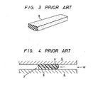
- unit segments 1 are used as work materials in constructing a shield tunnel excavated underground. These unit segments 1 are closely joined in the direction a along the peripheral wall and in the longitudinal direction b of the gallery.
- each of segments 1 there are provided front and rear flanges 2 and 3 extending in the circumferential direction a around the peripheral walls, and upper and lower flanges 4 and 5 extending in the longitudinal direction b.
- front and rear flanges 2 and 3 extending in the circumferential direction a around the peripheral walls, and upper and lower flanges 4 and 5 extending in the longitudinal direction b.
- a band-like joint sealing member 8 is secured by bonding onto one side of the flange surfaces facing gaps 7 between adjacent flange surfaces.
- a well-known water expansible material such as a material obtained by mixing, synthesizing and vulcanizing high hygroscopic resin and synthetic rubber is used.
- the sealing member 8 is formed into a single layer using the above-mentioned material. The sealing member 8 expands due to infiltration of water W into the joint so as to watertightly seal the gap 7.
- Fig. 2B depicts another prior art arrangement.
- a belt-like fitting groove for example, a groove 4a in the flange 4
- a joint member 8 is fixed in each of the fitting grooves.
- the surface of the joint member 8 projects from the outer surface of each of the flanges 2 and 4.
- the flanges 2 and 3 of the respective segments 1A and 1C are fixedly clamped together by three connecting bolts 6, and the flanges 4 and 5 of the respective segments 1A and 1B are fixedly clamped by two connecting bolts 6 such that the joint member 8 is compressed by a thickness t and the outer surface of the joint member 8 is urged against the outer surface of the flange 5 by elastic force, thereby effecting water stopping processing at the joint junction.
- the joint member 8 must be made thicker so as to sufficiently include the thickness t therein so that the joint member 8 largely projects from the flange 4. Accordingly, not only is a large amount of effort required for screwing on the nuts 6a, but also the projecting edge of the joint member 8 is apt to be caught thereby, causing the joint member 8 to slip out of the fitting groove 4a.
- the present invention has been attained to solve the difficulties mentioned above.
- a specific object of the present invention is to provide a joint sealing member mainly constituted by a water expansible material in which effective expansion in the direction of thickness can be obtained so that sideward hanging/expan- sion can be suppressed, stable bonding of the bottom surface of the sealing member can be obtained, and effective initial water stopping processing can be accomplished without increasing the thickness of the sealing member.
- a band-like joint sealing member is featured in that the band-like joint sealing member is constituted by joining a central expansible portion made of a water expansible material having a property of expansion of its volume upon absorbing water, and two lateral portions extending along said central portion made of nonexpansible rubber having a property of maintaining a constant volume even if in contact with water, the expansible and non- expansible portions being joined in the direction of width in the state where the expansible portion is sandwiched by the nonexpansible portions.
- the invention is characterised in that the central portion along its length protrudes substantially beyond the lateral portions and that the lateral portions are solely connected by means of the central portion.
- a sealing member 15 of a preferred embodiment is a longitundinally extending band-like member of a flexible material.
- this sealing member 15 is here shown as having a rectangluar shape in cross section, in the case where the shape of the joint junction to which the sealing joint is to be secured is ring-like, the joint member is shaped ring-like to conform with the shape of the joint junction.
- the sealing member 15 is constituted by three layers transversely joined with each other, one layer being an expansible thick portion 16 made of a water expansible rubber material, disposed at the center in the width direction, and having a transversely elongated rectangular cross-section, and the other layers being a pair of non-expansible portions 17 each made of a rubber material which is not water-expansible, disposed at the left and right sides of the expansible portion 16 and each having a rectangular cross-section and a bottom surface made even with that of the expansible portion 16.
- the thickness of each of the right and left nonexpansible portions 17 is made about two-thirds as thick as that of the expansible portion 16.
- the sealing member 15 is shaped such that the expansible portion 16 is projected upward at the center between the left and right nonexpansible portions 17.
- the expansible portion 16 is made of the above-mentioned well-known water expansible material, while each of the nonexpansible portions 17 is made of an ordinary rubber material, the volume of which does not change even if in contact with water.
- the bottom surface of the sealing member 15 is bonded and secured in the gap 7 between the adjacent flange surfaces or in an attachment groove formed in one of the flange surfaces by means of a bonding agent or the like.
- the projecting portion of the middle expansible portion 16 in the sealing material 15 closes a space between joints for initial water stopping at the beginning of joining. )t is not necessary to make the entire sealing material 15 thicker. Thus, there occurs no dislodging of the sealing member after time and the material cost is reduced.
- the expansible portion 16 absorbs water and expands so that the upper face of the sealing member 15 is pressed against the bonding surface so as to completely watertightly seal the joint.
- the sealing member expands effectively only in the direction of thickness to increase the elastic force of the upper surface thereof.
- the thickness over the nonexpansible portion 17 is small, and therefore the transversely expanded portion does not protrude sidewards from the upper surface of the nonexpansible portion 17 so that there is no risk of splitting of the expansible portion.
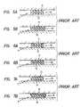
- the upper surface of the expansible portion 16 is made flat in the above-mentioned embodiment, the same effect can be obtained, alternatively, by forming a ridge portion having a curved cross-section in the widthwise direction, such as the sealing members 15A to 15E shown in Figs. 9A to 9E.
- the sealing members of the type shown in Figs. 9B to 9E provide better initial water stopping processing with the overall thickness of the material of the expansible portion 16 reduced.
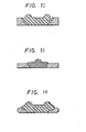
- the opposite side walls of the nonexpansible portion 17 are made vertical with respect to the bottom in the above- described embodiment, the same effect can be obtained in an alternative case where the side walls have trapezoidal tapered surfaces, such as the cross-section of the two kinds of sealing members 15F and 15G as shown in Figs. 10A and 10B.
- each of five kinds of sealing members 18A to 18E shown in Figs. 11A to 11E three layers are joined with each other, the middle one being an expansible portion 19A (19B-19E) and the other two disposed at the opposite sides of the expansible portion 19A being thin nonexpansible portions 20 each having an L-shaped cross section, the bottom of which extends towards the center in the widthwise direction. Further, a ridge portion 21 formed at the center of the lower surface of the expansible portion 19A (19B-19E) is exposed at the center in the widthwise direction of the bottom surface of the sealing member 18A (18B-18E).
- each of the thus arranged sealing members 18A-18E of this embodiment in addition to the effects of the above-mentioned first embodiment, there are further advantages that since the ratio of the nonexpansible portion 20 occupying the bottom bonding surface of each of the sealing members 18A-18E becomes large, the bonding force is made more stable and the sealing ability of the bonding surface is made surer.
- the amount of expensive water expansible material is reduced so that the production costs of the sealing member can be reduced.
- sealing members of the respective embodiments can be widely used for sealing junctions of secondary concrete products such as manholes, culvert boxes, or the like, in addition to the shield segments as described above.
- the joint sealing member according to the present invention is constituted by joined layers including a thick water expansible rubber portion positioned in the central portion in the widthwise direction of a band-like sealing member, and a pair of thin non-expansible rubber portions positioned on the opposite sides of the thick expansible rubber portion. Accordingly, the overall thickness can be reduced, the material costs reduced, and the sealing member can be prevented from becoming dislodged to thereby perform the water stopping processing effectively. There are further advantages that the water expansible rubber portion is effectively expanded in the direction of thickness and unwanted sideward expansion is suppressed so that attachment of the sealing member to the bonding surface is stabilized to thereby improve its ability of stopping water arid improve the durability of the sealing member.
Claims (4)
Applications Claiming Priority (4)
| Application Number | Priority Date | Filing Date | Title |
|---|---|---|---|
| JP192967/83 | 1983-12-16 | ||
| JP19296783U JPS60104498U (ja) | 1983-12-16 | 1983-12-16 | 土木工事用目地材 |
| JP43195/84 | 1984-03-28 | ||
| JP4319584U JPS60159099U (ja) | 1984-03-28 | 1984-03-28 | 目地シ−ル材 |
Related Child Applications (1)
| Application Number | Title | Priority Date | Filing Date |
|---|---|---|---|
| EP87107351.6 Division-Into | 1984-12-17 |
Publications (2)
| Publication Number | Publication Date |
|---|---|
| EP0147764A1 EP0147764A1 (de) | 1985-07-10 |
| EP0147764B1 true EP0147764B1 (de) | 1988-06-15 |
Family
ID=26382937
Family Applications (1)
| Application Number | Title | Priority Date | Filing Date |
|---|---|---|---|
| EP84115652A Expired EP0147764B1 (de) | 1983-12-16 | 1984-12-17 | Verbindungsdichtung |
Country Status (3)
| Country | Link |
|---|---|
| US (1) | US5390939A (de) |
| EP (1) | EP0147764B1 (de) |
| DE (2) | DE3482887D1 (de) |
Families Citing this family (48)
| Publication number | Priority date | Publication date | Assignee | Title |
|---|---|---|---|---|
| EP0244877B2 (de) | 1983-12-16 | 1993-03-31 | C.I. Kasei Co., Ltd | Verbindungsdichtung |
| FR2602543B1 (fr) * | 1986-08-08 | 1988-11-04 | Phoenix Ag | Joint d'etancheite profile pour segments de tube destines a etre assembles en un tunnel |
| DE3779123D1 (de) * | 1987-09-10 | 1992-06-17 | Joint Francais | Dichtungselement fuer tunnelausbausegmente. |
| US5172919A (en) * | 1990-02-22 | 1992-12-22 | C. I. Kasei Co., Ltd. | Appliance for preventing water from leaking through joint |
| US5297806A (en) * | 1991-08-08 | 1994-03-29 | Dana Corporation | Method of making multi-density composite gaskets |
| HU218188B (hu) * | 1992-09-04 | 2000-06-28 | N.V. Raychem S.A. | Tömítőegység, valamint ilyen tömítőegységgel ellátott csatlakoztató-szerelvény, főleg optikai kábelekhez |
| US5584488A (en) * | 1994-03-02 | 1996-12-17 | Baker Hughes Incorporatd | Seal |
| WO1996023958A1 (de) * | 1995-02-01 | 1996-08-08 | Phoenix Aktiengesellschaft | Dichtanordnung für insbesondere tunnelrohrsegmente |
| ES2122802T3 (es) * | 1995-03-01 | 1998-12-16 | Phoenix Ag | Junta de estanqueidad y su procedimiento de realizacion. |
| FR2732433B1 (fr) * | 1995-03-28 | 1997-06-13 | Soc D Tuyaux Bonna | Joint d'etancheite et son procede de realisation |
| US5578790A (en) * | 1995-09-06 | 1996-11-26 | The Whitaker Corporation | Shielding gasket |
| DE19736431C2 (de) * | 1997-08-21 | 2003-01-02 | Bruss Dichtungstechnik | Statische Dichtungsanordnung |
| GB2328989B (en) * | 1997-09-09 | 2001-11-28 | T & N Technology Ltd | Gaskets |
| US6073938A (en) * | 1997-11-06 | 2000-06-13 | Kokusan Parts Industry Co., Ltd. | Sealing structure |
| EP0922888B1 (de) * | 1997-12-10 | 2003-05-21 | Festo AG & Co | Dichtungsring |
| GB2340896B (en) * | 1998-08-26 | 2002-09-11 | Tarmac Uk Ltd | Edge seal assembly |
| DE50109672D1 (de) * | 2000-03-30 | 2006-06-08 | Phoenix Ag | Dichtanordnung für tunnelbausegmente |
| US6787489B2 (en) | 2001-12-12 | 2004-09-07 | Multisorb Technologies, Inc. | Absorbent mixture and product |
| US20030209863A1 (en) * | 2002-03-21 | 2003-11-13 | Kyle Gregoire | Self-aligning sealing apparatus providing axial sealing and controlled compression limits |
| FR2846067B1 (fr) * | 2002-10-18 | 2005-01-14 | Valeo Vision | Joint d'etancheite pour bloc optique automobile |
| US6844845B1 (en) * | 2003-01-06 | 2005-01-18 | Garmin Ltd. | Waterproof combined global positioning system receiver and two-way radio and method of waterproof enclosure fabrication |
| DE102004045142A1 (de) | 2003-09-17 | 2005-07-07 | Uchiyama Manufacturing Corp. | Zylinderkopfdichtung |
| GB0329890D0 (en) * | 2003-12-23 | 2004-01-28 | Airbus Uk Ltd | Method of Sealing a Joint |
| US7282097B2 (en) * | 2004-06-14 | 2007-10-16 | Applied Materials, Inc. | Slit valve door seal |
| US7213814B2 (en) * | 2004-07-28 | 2007-05-08 | Federal-Mogul Worldwide, Inc. | Seal assembly |
| US20060237463A1 (en) * | 2005-04-21 | 2006-10-26 | Tony Riviezzo | Component seal for plastic tanks |
| US20080106044A1 (en) * | 2006-11-07 | 2008-05-08 | Ngoc Minh Luong | Sealing system and gasket with spaces |
| US20090126947A1 (en) * | 2007-05-31 | 2009-05-21 | Baker Hughes Incorporated | Swellable material and method |
| GB0720705D0 (en) * | 2007-10-23 | 2007-12-05 | Airbus Uk Ltd | Fastener joint with sealing gasket |
| WO2009055507A1 (en) * | 2007-10-26 | 2009-04-30 | Applied Materials, Inc. | Methods and apparatus for sealing a slit valve door |
| JP5173732B2 (ja) * | 2008-10-23 | 2013-04-03 | Nok株式会社 | ガスケット |
| US9085964B2 (en) * | 2009-05-20 | 2015-07-21 | Halliburton Energy Services, Inc. | Formation tester pad |
| US20110129300A1 (en) * | 2009-11-30 | 2011-06-02 | Dimillo Tony | Steel liners for tunnels |
| JP5636613B2 (ja) * | 2010-05-19 | 2014-12-10 | Smc株式会社 | 流体圧機器 |
| JP5621092B2 (ja) | 2010-05-19 | 2014-11-05 | Smc株式会社 | 流体圧機器 |
| JP5621091B2 (ja) | 2010-05-19 | 2014-11-05 | Smc株式会社 | 流体圧機器 |
| EP2407641A1 (de) * | 2010-07-13 | 2012-01-18 | Siemens Aktiengesellschaft | Dichtelement zur Dichtung eines Spalts sowie Dichtungsanordnung |
| JP5604345B2 (ja) * | 2011-03-23 | 2014-10-08 | カヤバ工業株式会社 | 流体圧シリンダのピストン軸受け構造 |
| US9377107B2 (en) * | 2011-10-20 | 2016-06-28 | The University Of Akron | Seals having textured portions for protection in space environments |
| JP5739318B2 (ja) * | 2011-12-21 | 2015-06-24 | シーアイ化成株式会社 | トンネル用セグメントの止水構造及びトンネル用セグメントの施工方法 |
| FR2995961B1 (fr) * | 2012-09-26 | 2014-10-17 | Joint Francais | Joint annulaire, et moule de fabrication d'un tel joint. |
| JP2014092191A (ja) * | 2012-11-01 | 2014-05-19 | Nok Corp | 基材一体型シール及びその製造用金型 |
| CA2829072C (en) | 2013-10-02 | 2020-03-10 | Canplas Industries Ltd. | Bathtub drain and overflow kit |
| US10316604B2 (en) * | 2014-07-02 | 2019-06-11 | Utex Industries, Inc. | Inflatable seal with fabric expansion restriction |
| JP6597477B2 (ja) | 2016-05-24 | 2019-10-30 | 株式会社デンソー | バルブ装置 |
| US9926762B1 (en) * | 2016-11-11 | 2018-03-27 | Baker Hughes, A Ge Company, Llc | Downhole sealing apparatus |
| CN108952777A (zh) * | 2018-09-21 | 2018-12-07 | 中铁第四勘察设计院集团有限公司 | 一种盾构隧道新型复合式防水密封垫 |
| US20210317934A1 (en) * | 2020-04-09 | 2021-10-14 | Todd Anthony Travis | Retaining ring system and method of use |
Family Cites Families (22)
| Publication number | Priority date | Publication date | Assignee | Title |
|---|---|---|---|---|
| DE565642C (de) * | 1931-04-12 | 1932-12-05 | Stromeier & Co G | Dichtungsring, insbesondere fuer UEberhitzerelemente, der aus Aluminium und einem haerteren Metall besteht |
| US2373443A (en) * | 1943-07-05 | 1945-04-10 | Euclid Road Machinery Co | Sealing means |
| US2646677A (en) * | 1948-02-04 | 1953-07-28 | Firestone Tire & Rubber Co | Means for sealing containers for pressure testing |
| GB656032A (en) * | 1948-10-21 | 1951-08-08 | Vickers Armstrongs Ltd | Improvements in or relating to pipe joints and the like |
| GB701614A (en) * | 1951-06-27 | 1953-12-30 | Vickers Electrical Co Ltd | Improvements relating to the sealing of joints in high vacuum and the like systems |
| GB836584A (en) * | 1955-03-31 | 1960-06-09 | Hans Ziller | Improvements relating to sealing or packing rings |
| GB805253A (en) * | 1955-11-25 | 1958-12-03 | Trist & Co Ltd Ronald | Improvements relating to packing rings |
| US2849070A (en) * | 1956-04-02 | 1958-08-26 | Union Oil Co | Well packer |
| US3099110A (en) * | 1957-09-17 | 1963-07-30 | Dur O Wal National Inc | Control joint |
| US3094337A (en) * | 1960-10-31 | 1963-06-18 | Universal Packing & Gasket Com | Seal ring |
| US3166332A (en) * | 1961-05-26 | 1965-01-19 | Olson Richard Laurence | Pressure assembly comprising a sealing strip of elastomeric material having compressible gas cells |
| US3153541A (en) * | 1962-07-13 | 1964-10-20 | Rudder Elbert | Gasket assembly |
| GB1072891A (en) * | 1964-02-01 | 1967-06-21 | Prec Rubbers Ltd | Improvements in rubber sealing strips |
| US3355181A (en) * | 1964-11-18 | 1967-11-28 | Dike O Seal Inc | Sealing structures embodying closed cell elastomeric material |
| US3490776A (en) * | 1967-11-01 | 1970-01-20 | Cresskill Stillman Rubber Corp | Fluid gasket seal |
| DE2513365C3 (de) * | 1975-03-26 | 1982-09-30 | Ruhrkohle Ag, 4300 Essen | Anordnung zur Abdichtung der Fugen von Stahlbetontübbingausbau |
| US4059280A (en) * | 1975-07-02 | 1977-11-22 | Hall & Hall Limited | Seal ring assembly |
| DE2833345C2 (de) * | 1978-07-29 | 1985-03-28 | Phoenix Ag, 2100 Hamburg | Dichtungsprofil für Tübbings |
| CA1145131A (en) * | 1980-04-05 | 1983-04-26 | Hajime Yamaji | Aqueously-swelling water stopper and a process of stopping water thereby |
| US4305595A (en) * | 1980-04-30 | 1981-12-15 | Hydril Company | Composite seal |
| DE3200242A1 (de) * | 1982-01-07 | 1983-07-14 | Friedrich-Wilhelm von Dr.-Ing. 8720 Schweinfurt Hackewitz | Durch erwaermung und/oder fluessigkeitsaufnahme an seiner oberflaeche woelbbares element aus kunststoff o.dgl., verfahren zu seiner herstellung und anwendung desselben |
| JPS58187655A (ja) * | 1982-04-28 | 1983-11-01 | Kajima Corp | セグメントの継手 |
-
1984
- 1984-12-17 DE DE8787107351T patent/DE3482887D1/de not_active Expired - Fee Related
- 1984-12-17 EP EP84115652A patent/EP0147764B1/de not_active Expired
- 1984-12-17 DE DE8484115652T patent/DE3472132D1/de not_active Expired
-
1990
- 1990-12-19 US US07/629,173 patent/US5390939A/en not_active Expired - Lifetime
Also Published As
| Publication number | Publication date |
|---|---|
| DE3482887D1 (de) | 1990-09-06 |
| EP0147764A1 (de) | 1985-07-10 |
| DE3472132D1 (en) | 1988-07-21 |
| US5390939A (en) | 1995-02-21 |
Similar Documents
| Publication | Publication Date | Title |
|---|---|---|
| EP0147764B1 (de) | Verbindungsdichtung | |
| US4967800A (en) | Secondary confinement pipe having segments with interlocking rib and groove joints and coextruded sealant layers #4 | |
| US3712016A (en) | Method for sealing grooves in structure concrete sealing | |
| IE911998A1 (en) | Method for sealing connections between sheet piles, and¹sheet piles employing said method | |
| US4662773A (en) | Segmental tunnel lining consisting of reinforced concrete tubbings | |
| AU2017275444B2 (en) | Sealing string for sealing a joint between components, and method for manufacturing same | |
| US6612585B2 (en) | Elastomeric strand-shaped sealing profile | |
| US3935682A (en) | Cleaning fasteners | |
| JPH0444719Y2 (de) | ||
| EP0244877B1 (de) | Verbindungsdichtung | |
| JP4508770B2 (ja) | 土木建築用目地シール材とそれを用いたシールドトンネル構造物のシール構造 | |
| EP0010883B1 (de) | Verbesserung an einem spalterzeugenden und abdichtenden Band | |
| JPH08232279A (ja) | 土木工事用セグメントの止水構造 | |
| JPH11182685A (ja) | 複合シール材とそのシール構造 | |
| GB2241973A (en) | Waterproofing of tunnel lining | |
| JPH08135132A (ja) | 外壁材の乾式目地材 | |
| US3696577A (en) | Prefabricated reinforced concrete plate shaped construction element | |
| JP3181530B2 (ja) | 排水路の止水構造 | |
| JPH07197552A (ja) | 建築用材のシーリング構造 | |
| JPH0442406Y2 (de) | ||
| JP2001059397A (ja) | コンクリート製セグメント | |
| JPH0713438B2 (ja) | セグメントコーナー部のシール構造とその施工方法 | |
| JPH0452320Y2 (de) | ||
| JPH0437998Y2 (de) | ||
| SU1404408A1 (ru) | Уплотнение грузового трюма саморазгружающейс шаланды |
Legal Events
| Date | Code | Title | Description |
|---|---|---|---|
| PUAI | Public reference made under article 153(3) epc to a published international application that has entered the european phase |
Free format text: ORIGINAL CODE: 0009012 |
|
| AK | Designated contracting states |
Designated state(s): CH DE FR GB LI NL |
|
| 17P | Request for examination filed |
Effective date: 19851209 |
|
| 17Q | First examination report despatched |
Effective date: 19861021 |
|
| D17Q | First examination report despatched (deleted) | ||
| GRAA | (expected) grant |
Free format text: ORIGINAL CODE: 0009210 |
|
| AK | Designated contracting states |
Kind code of ref document: B1 Designated state(s): CH DE FR GB LI NL |
|
| REF | Corresponds to: |
Ref document number: 3472132 Country of ref document: DE Date of ref document: 19880721 |
|
| ET | Fr: translation filed | ||
| PLBE | No opposition filed within time limit |
Free format text: ORIGINAL CODE: 0009261 |
|
| STAA | Information on the status of an ep patent application or granted ep patent |
Free format text: STATUS: NO OPPOSITION FILED WITHIN TIME LIMIT |
|
| 26N | No opposition filed | ||
| PGFP | Annual fee paid to national office [announced via postgrant information from national office to epo] |
Ref country code: DE Payment date: 20001219 Year of fee payment: 17 |
|
| PGFP | Annual fee paid to national office [announced via postgrant information from national office to epo] |
Ref country code: NL Payment date: 20001231 Year of fee payment: 17 |
|
| PGFP | Annual fee paid to national office [announced via postgrant information from national office to epo] |
Ref country code: CH Payment date: 20010301 Year of fee payment: 17 |
|
| PG25 | Lapsed in a contracting state [announced via postgrant information from national office to epo] |
Ref country code: LI Free format text: LAPSE BECAUSE OF NON-PAYMENT OF DUE FEES Effective date: 20011231 Ref country code: CH Free format text: LAPSE BECAUSE OF NON-PAYMENT OF DUE FEES Effective date: 20011231 |
|
| REG | Reference to a national code |
Ref country code: GB Ref legal event code: IF02 |
|
| PG25 | Lapsed in a contracting state [announced via postgrant information from national office to epo] |
Ref country code: NL Free format text: LAPSE BECAUSE OF NON-PAYMENT OF DUE FEES Effective date: 20020701 |
|
| PG25 | Lapsed in a contracting state [announced via postgrant information from national office to epo] |
Ref country code: DE Free format text: LAPSE BECAUSE OF NON-PAYMENT OF DUE FEES Effective date: 20020702 |
|
| REG | Reference to a national code |
Ref country code: CH Ref legal event code: PL |
|
| NLV4 | Nl: lapsed or anulled due to non-payment of the annual fee |
Effective date: 20020701 |
|
| PGFP | Annual fee paid to national office [announced via postgrant information from national office to epo] |
Ref country code: FR Payment date: 20021210 Year of fee payment: 19 |
|
| PGFP | Annual fee paid to national office [announced via postgrant information from national office to epo] |
Ref country code: GB Payment date: 20031217 Year of fee payment: 20 |
|
| PG25 | Lapsed in a contracting state [announced via postgrant information from national office to epo] |
Ref country code: FR Free format text: LAPSE BECAUSE OF NON-PAYMENT OF DUE FEES Effective date: 20040831 |
|
| REG | Reference to a national code |
Ref country code: FR Ref legal event code: ST |
|
| PG25 | Lapsed in a contracting state [announced via postgrant information from national office to epo] |
Ref country code: GB Free format text: LAPSE BECAUSE OF EXPIRATION OF PROTECTION Effective date: 20041216 |
|
| REG | Reference to a national code |
Ref country code: GB Ref legal event code: PE20 |