EP0147731A2 - Arbeitsbühne für den Bau - Google Patents
Arbeitsbühne für den Bau Download PDFInfo
- Publication number
- EP0147731A2 EP0147731A2 EP84115343A EP84115343A EP0147731A2 EP 0147731 A2 EP0147731 A2 EP 0147731A2 EP 84115343 A EP84115343 A EP 84115343A EP 84115343 A EP84115343 A EP 84115343A EP 0147731 A2 EP0147731 A2 EP 0147731A2
- Authority
- EP
- European Patent Office
- Prior art keywords
- rail
- walkway
- rails
- handle
- perforations
- Prior art date
- Legal status (The legal status is an assumption and is not a legal conclusion. Google has not performed a legal analysis and makes no representation as to the accuracy of the status listed.)
- Withdrawn
Links
Images


Classifications
-
- E—FIXED CONSTRUCTIONS
- E04—BUILDING
- E04G—SCAFFOLDING; FORMS; SHUTTERING; BUILDING IMPLEMENTS OR AIDS, OR THEIR USE; HANDLING BUILDING MATERIALS ON THE SITE; REPAIRING, BREAKING-UP OR OTHER WORK ON EXISTING BUILDINGS
- E04G1/00—Scaffolds primarily resting on the ground
- E04G1/18—Scaffolds primarily resting on the ground adjustable in height
- E04G1/20—Scaffolds comprising upright members and provision for supporting cross-members or platforms at different positions therealong
Definitions
- the present invention relates to walkways which can be raised up the sides of buildings and the like for ise in construction or renovation of buildings and similar operations.
- the present invention provides a walkway system which-comprises perforated rails fixed directly or indirectly to a structure and a walkway having mounted thereon manually operable elements cooperable with the perforations in said rails to cause the walkways to be raised or lowered on said rails and manually operable elements to secure said walkways at a desired position on the rails.
- Rails can be fixed to a structure in any convenient way. I have found that my new walkway system is of particular use in conjunction with the building system described in my co-pending application Serial No. 537,500, filed September 30, 1983 the contents of which are incorporated herein by reference. In this case, the rails of the present invention may, on occasion, be afixed to the mold structure used for the construction of the buildings.
- rails for use in the present invention are metal profiles which are shaped so as to surround an open area and have a space along one side. Perforations are provided in the sall of the rail containing the space on both sides of the space or on the two "side walls" and also in the wall opposite that containing the space. Conveniently, the profile may have the cross section of a Greek cross with one limb thereof removed to provide the space.
- the wall opposite that with the space is affixed to the building or possibly when the walkway is to be used in conjunction with the building system of my aforementioned to pending application, the mold assembly being constructed.
- the elevator apparatus of the walkway which comprises manually operable wheels containing projections or spokes extending from the wheels which cooperate with the perforations in the side wall of the rail.
- wheels may be provided with an orientation in which they cooperate witn perforations on the two side walls of the rail.
- the walkways are also provided with manually operable latches which can cooperate with the perforations in the rails to stabilize the walkway at a desired height.
- the system of the present invention comprises a rail 100 which is a hollow profile the perimeter of which is essentially in the shape of a Greek cross having one limb removed.
- the rail is shown in more detail in Figure 3.
- the missing limb of the Greek cross leaves a gap 101 in the rail.
- the positions of the profile on either side of the gap 101 are provided with perforations 102.
- the opposite side of the rail to the gap 101 is also provided with perforations 103, and the two sides adjacent to that wall are provided with perforations 104.
- the rails are typically attached to the structures on which the walkways are to be used by, for example, bolting them to the structure by bolts passing through the perforations 103.
- the rail is typically made of steel.
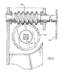
- the sliding element sits within the hollow in the interior of the rail profile 100.
- the sliding element 200 itself comprises a metal normally steel, profile 201 of a substantially "squared U-shape" configuration.
- To this profile are attached the supports for the walkway 300 (shown in more detail in Figures 4 and 13), the latch mechanism 220, 221, 222, 224, (shown in more detail in Figures 4, 5 and 6), a handle 204 which itself has mounted on it a further latch mechanism 211, 212, 213, 214, 215, 216 (shown in more detail in Figures 8 and 9), the ascent and descent mechanism 205, 206, 207 (shown in more detail in Figure 12), guide rollers 202 and a guard ring 230.
- the guide rollers 202 are mounted on an axle that perforates the profile base 201 of the sliding element. They are positioned so as to rotate against that position of the rail that contains the perforations 102 i.e. the "frontal" side of the rail and thereby to facilitate movement of the sliding element up and down the rail.
- Two pins 203 also perforate the profile 201 and serve as fastening elements for the tubular or solid structure of support for the walkways 300.
- the handle 204 actuates a worm drive 205 mounted on the profile 201 that cooperates with a crown gear 206 mounted on an axle 207 which is preferably of a non- cylindrical shape to avoid the sliding.
- the escalator wheels 208 are mounted on and actuated by the axle 207. The projections of the escalator wheels interact with the regular perforations 102 existing in the frontal side of the rail 100; with which will all move the part of the sliding element 200, and with it, the moveable walkway.
- a latch 210 is positioned on the handle 204.
- This latch comprises a handle 211 which is moveable between a retracted and an extended position under the influence of spring 213. In its retracted position, the latch handle 211 is restained by retainer 212. It may, however be released from the retainer by rotation and will then be urged into its extended position into the influence of the spring 313.
- latch element 220 fixed across the opening of the U of profile 201 is latch element 220. This element is in operation exterior to the rail 100.
- the latch 200 normally consists of a laminar metallic base 221 joined to the body of the profile 201, on which is mounted an axle, that spins on two perforated platens 223 joined to the base 221.
- On one of the ends of the axle 222 is a counter-weight 224 which actuates the same axle, moving at a direction toward the rail 100 so that two wedges 225, mounted on the axle 222 may be caused to penetrate through the perforations 102, thereby immobilizing the sliding and walkway.
- the security ring 230 is fastened over the surface of the profile 201.
- the solid or tubular structure of support 300 fastened to the sliding element 200 through which the pins 203, may be solid or tubular, of certain resistance, formed by elements that reinforce among each other, and on their opposite end 301 can have two perforated tubes, at a parallel direction to the sliding element 200 by which other tubes may go through 302, also perforated, which acting in a telescopic manner will serve to support and fix on them the elements of support 400 in the shape of a railing.
- the profile of "U" shape is joined to the structure 300, and the mentioned profile at the same time is joined to the elements of support 400 through the perforations 305, and the perforations 402.
- the elements of support 400 to be fastened to the structure 300 as well as a zone of protection with railing, may be made of metallic sheet with end of profile shapes and perforations along its length, with the object of serving as a form of union on every dimension, at the same time that they prevent the sliding when used by the workers.
- the several elements of support 400 are several perforated metal sheets joined together by screws.
- the lowest element of the rail wherein the sliding element is mounted is affixed to a vertical wall of the structure to be constructed or repaired.
- the rails, walkways and sliding elements of the present invention can all be assembled on site.
- the lowest element of the rail is attached to a vertical wall of the structure to be constructed or repaired and the support elements for the walkway 300 are attached by pins 203 to the sliding element 200.
- the sliding element is then inserted into the rail and the remainder of the walkway constructed.
- the projections on the escalator wheels 208 will interact with the perforations 102 in the rail 100.
- the handle 204 is rotated to turn the worm gear 205 in the "descent" direction so as to rotate the crown gear 206 and the escalator wheels 208 in the "descent” direction thereby permitting the interaction with the perforations.
- the spacing of the perforations 102 and the positions of the escalator wheel 208 and the dimensions of the projections thereon are chosen to permit the projections to pass through are perforation 102 and as rotation remain inserted in that perforation until the adjacent projection is fully inserted in the next perforation.
- the walkway 300 is assembled on the basis of the support members as shown in Figures 2, 4 and 13.
- the next length of rail may be positioned above and abutting with the first.
- the walkway may then be caused to ascend the rails by rotation of the handle 204 in the opposite direction from that in which it was turned during its introduction to the rails.
- the latch 220 is held “open” during the ascent by lefting the counterweight from its “rest” position.
- the latch mechanisms are activated to prevent rotation of handle 204 by causing its latch handle 211 to be moved to its extended position thereby as a result of its interaction with the rails 100 preventing further rotation of the handle 204 until the latch handle is returned to its next position on the retainer 201 and activating latch 220 to cause its projections 225 pass through the holes 102 of the rails 100 thereby stabilizing the position of the walkway.
- the walkway can be used for building and the like operations or if desired as a platform from which further rails can be affixed to the structure so as to permit the walkway to be raised higher.
Landscapes
- Engineering & Computer Science (AREA)
- Architecture (AREA)
- Mechanical Engineering (AREA)
- Civil Engineering (AREA)
- Structural Engineering (AREA)
- Escalators And Moving Walkways (AREA)
- Refuge Islands, Traffic Blockers, Or Guard Fence (AREA)
- Movable Scaffolding (AREA)
Applications Claiming Priority (2)
| Application Number | Priority Date | Filing Date | Title |
|---|---|---|---|
| US06/563,667 US4534446A (en) | 1983-12-20 | 1983-12-20 | Movable walkway system of use in the construction industry |
| US563667 | 1983-12-20 |
Publications (2)
| Publication Number | Publication Date |
|---|---|
| EP0147731A2 true EP0147731A2 (de) | 1985-07-10 |
| EP0147731A3 EP0147731A3 (de) | 1986-12-30 |
Family
ID=24251439
Family Applications (1)
| Application Number | Title | Priority Date | Filing Date |
|---|---|---|---|
| EP84115343A Withdrawn EP0147731A3 (de) | 1983-12-20 | 1984-12-13 | Arbeitsbühne für den Bau |
Country Status (8)
| Country | Link |
|---|---|
| US (1) | US4534446A (de) |
| EP (1) | EP0147731A3 (de) |
| JP (1) | JPS60148955A (de) |
| AU (1) | AU3686784A (de) |
| BR (1) | BR8406560A (de) |
| ES (1) | ES8507650A1 (de) |
| FR (1) | FR2556763A1 (de) |
| MX (1) | MX162846B (de) |
Cited By (2)
| Publication number | Priority date | Publication date | Assignee | Title |
|---|---|---|---|---|
| WO1997022768A1 (de) * | 1995-09-22 | 1997-06-26 | Paul Lingen | Mast für ein baugerüst oder einen baulift |
| EP2639382A1 (de) * | 2012-03-14 | 2013-09-18 | Demat Comm. V. | Arbeitsplattform |
Families Citing this family (7)
| Publication number | Priority date | Publication date | Assignee | Title |
|---|---|---|---|---|
| GB2184697A (en) * | 1985-12-31 | 1987-07-01 | Rydal Precision Engineering Co | Foldable trolley base |
| JPH0681454A (ja) * | 1992-08-31 | 1994-03-22 | Kunimoto Shokai:Kk | 足場板支持装置 |
| US5487446A (en) * | 1994-05-09 | 1996-01-30 | Patnode; Eric T. | Apparatus for self-adjusting the height of an outrigger attachable to scaffolding |
| US5799750A (en) * | 1996-12-31 | 1998-09-01 | Garcia; Guadalupe | Portable scaffold |
| US6182791B1 (en) | 1998-06-19 | 2001-02-06 | James L. Cope | Adjustable scaffolding and lift carriage and support member therefor |
| US20110186795A1 (en) * | 2010-02-04 | 2011-08-04 | Samuel Manu-Tech Inc. | Highway Guardrail Post |
| JP7096468B1 (ja) * | 2021-08-25 | 2022-07-06 | 椿建設株式会社 | 飛散防止ネットの張り構造および飛散防止ネットの張り方法 |
Family Cites Families (9)
| Publication number | Priority date | Publication date | Assignee | Title |
|---|---|---|---|---|
| US1307610A (en) * | 1919-06-24 | Building-scaffold | ||
| GB150011A (en) * | 1919-09-24 | 1920-09-02 | Archibald Malcolm Allan | Improvements in and relating to stagings or supports for use in structural engineering, bridge building and the like |
| US1442075A (en) * | 1921-11-09 | 1923-01-16 | Abel M Knechtel | Scaffold hoist |
| US1474249A (en) * | 1922-07-17 | 1923-11-13 | Ferrero John | Adjustable platform |
| US2007480A (en) * | 1934-06-20 | 1935-07-09 | Gustav A Schernekau | Builder's scaffold |
| FR1415335A (fr) * | 1964-12-01 | 1965-10-22 | Perfectionnements aux échafaudages munis d'un pont mobile autoélévateur et constitués par des éléments préfabriqués susceptibles d'être reliés entre eux d'une manière facilement démontable | |
| US3323616A (en) * | 1965-10-22 | 1967-06-06 | Frank S Best | Mason's scaffold |
| US3438460A (en) * | 1966-11-09 | 1969-04-15 | Louis J Solari | Scaffold with elevatable section |
| US3548970A (en) * | 1968-08-05 | 1970-12-22 | Ralph W Hutchens Sr | Scaffolding and material handling system |
-
1983
- 1983-12-20 US US06/563,667 patent/US4534446A/en not_active Expired - Fee Related
-
1984
- 1984-12-06 MX MX203614A patent/MX162846B/es unknown
- 1984-12-13 EP EP84115343A patent/EP0147731A3/de not_active Withdrawn
- 1984-12-18 JP JP59267281A patent/JPS60148955A/ja active Pending
- 1984-12-18 FR FR8419345A patent/FR2556763A1/fr not_active Withdrawn
- 1984-12-18 AU AU36867/84A patent/AU3686784A/en not_active Abandoned
- 1984-12-19 BR BR8406560A patent/BR8406560A/pt unknown
- 1984-12-19 ES ES538799A patent/ES8507650A1/es not_active Expired
Cited By (2)
| Publication number | Priority date | Publication date | Assignee | Title |
|---|---|---|---|---|
| WO1997022768A1 (de) * | 1995-09-22 | 1997-06-26 | Paul Lingen | Mast für ein baugerüst oder einen baulift |
| EP2639382A1 (de) * | 2012-03-14 | 2013-09-18 | Demat Comm. V. | Arbeitsplattform |
Also Published As
| Publication number | Publication date |
|---|---|
| AU3686784A (en) | 1985-07-04 |
| ES538799A0 (es) | 1985-09-01 |
| BR8406560A (pt) | 1985-10-15 |
| EP0147731A3 (de) | 1986-12-30 |
| MX162846B (es) | 1991-06-28 |
| JPS60148955A (ja) | 1985-08-06 |
| US4534446A (en) | 1985-08-13 |
| ES8507650A1 (es) | 1985-09-01 |
| FR2556763A1 (fr) | 1985-06-21 |
Similar Documents
| Publication | Publication Date | Title |
|---|---|---|
| US4534446A (en) | Movable walkway system of use in the construction industry | |
| EP0064183B1 (de) | Kletterschalung | |
| US5992565A (en) | Lifting scaffold assembly | |
| US6981573B2 (en) | Scaffold lift system | |
| CN109468963B (zh) | 桥梁高空作业吊篮及桥梁高空施工方法 | |
| US3394776A (en) | Suspended traveling scaffold | |
| DE69523583T2 (de) | Hebestufeneinrichtung | |
| CN109610807B (zh) | 一种折叠护栏以及包含其的高架作业台 | |
| DE102005013991B3 (de) | Fahrbares Arbeitsgerüst | |
| US3908792A (en) | Passenger carrying assembly | |
| DE2949429C2 (de) | Rettungssystem an Hochhäusern für die Rettung von Personen im Brandfalle | |
| DE19814639A1 (de) | Aufzugsanlage und Verfahren zu deren Anbindung an das Treppenhaus eines bestehenden, in Plattenbauweise hergestellten Gebäudes | |
| DE3114602A1 (de) | Einrichtung fuer arbeitsgerueste mit heb- und senkbarer arbeitsbuehne | |
| JPS623477Y2 (de) | ||
| JP7514574B1 (ja) | 作業用ゴンドラ装置およびゴンドラ仮固定装置 | |
| CN220768987U (zh) | 可拓展作业空间的房建施工平台 | |
| DE4219732C2 (de) | Montagegerüst | |
| RU210356U1 (ru) | Площадка передвижная с лестницей для входа в кабину машиниста и обслуживания подвижного состава | |
| CN113175202B (zh) | 一种可移动支撑的电梯井施工操作平台 | |
| JPH0344800Y2 (de) | ||
| JPH027136Y2 (de) | ||
| SU768914A1 (ru) | Подмости дл производства работ внутри цилиндрического резервуара | |
| DE2504665A1 (de) | Geraet zur personenrettung aus gebaeuden bei feuergefahr | |
| JPS6222595Y2 (de) | ||
| SU1281658A1 (ru) | Самоподъемные подмости |
Legal Events
| Date | Code | Title | Description |
|---|---|---|---|
| PUAI | Public reference made under article 153(3) epc to a published international application that has entered the european phase |
Free format text: ORIGINAL CODE: 0009012 |
|
| AK | Designated contracting states |
Designated state(s): AT DE FR GB IT |
|
| PUAL | Search report despatched |
Free format text: ORIGINAL CODE: 0009013 |
|
| AK | Designated contracting states |
Kind code of ref document: A3 Designated state(s): AT DE FR GB IT |
|
| STAA | Information on the status of an ep patent application or granted ep patent |
Free format text: STATUS: THE APPLICATION IS DEEMED TO BE WITHDRAWN |
|
| 18D | Application deemed to be withdrawn |
Effective date: 19870701 |