EP0147525A1 - Machine de traitement par laser - Google Patents
Machine de traitement par laser Download PDFInfo
- Publication number
- EP0147525A1 EP0147525A1 EP84109857A EP84109857A EP0147525A1 EP 0147525 A1 EP0147525 A1 EP 0147525A1 EP 84109857 A EP84109857 A EP 84109857A EP 84109857 A EP84109857 A EP 84109857A EP 0147525 A1 EP0147525 A1 EP 0147525A1
- Authority
- EP
- European Patent Office
- Prior art keywords
- laser
- mirror
- machine according
- laser beam
- test
- Prior art date
- Legal status (The legal status is an assumption and is not a legal conclusion. Google has not performed a legal analysis and makes no representation as to the accuracy of the status listed.)
- Granted
Links
Images


Classifications
-
- B—PERFORMING OPERATIONS; TRANSPORTING
- B23—MACHINE TOOLS; METAL-WORKING NOT OTHERWISE PROVIDED FOR
- B23K—SOLDERING OR UNSOLDERING; WELDING; CLADDING OR PLATING BY SOLDERING OR WELDING; CUTTING BY APPLYING HEAT LOCALLY, e.g. FLAME CUTTING; WORKING BY LASER BEAM
- B23K26/00—Working by laser beam, e.g. welding, cutting or boring
- B23K26/08—Devices involving relative movement between laser beam and workpiece
- B23K26/10—Devices involving relative movement between laser beam and workpiece using a fixed support, i.e. involving moving the laser beam
-
- B—PERFORMING OPERATIONS; TRANSPORTING
- B23—MACHINE TOOLS; METAL-WORKING NOT OTHERWISE PROVIDED FOR
- B23K—SOLDERING OR UNSOLDERING; WELDING; CLADDING OR PLATING BY SOLDERING OR WELDING; CUTTING BY APPLYING HEAT LOCALLY, e.g. FLAME CUTTING; WORKING BY LASER BEAM
- B23K26/00—Working by laser beam, e.g. welding, cutting or boring
- B23K26/02—Positioning or observing the workpiece, e.g. with respect to the point of impact; Aligning, aiming or focusing the laser beam
- B23K26/04—Automatically aligning, aiming or focusing the laser beam, e.g. using the back-scattered light
- B23K26/042—Automatically aligning the laser beam
- B23K26/043—Automatically aligning the laser beam along the beam path, i.e. alignment of laser beam axis relative to laser beam apparatus
Definitions
- the invention relates to a machine for processing a workpiece by means of a laser beam, the position of the laser beam being adjustable by means of at least one mirror.
- the workpieces to be machined are preferably sheets of small to medium thickness.
- workpieces or breakthroughs can be burned out from the starting material, for example a sheet metal plate, the burn marks possibly being very close to one another.
- the laser cutting process is suitable for the production of both individual pieces and of medium series with complicated shapes.
- a workpiece or an opening can be created in a very short time, whereby there can also be openings of circular or any contour within a workpiece. By changing the program, you can easily change a defined shape in any way.
- sheet metal In the known machines of this type, the workpiece is subsequently referred to as "sheet metal" for the sake of simplicity, without this being allowed to be interpreted restrictively, by means of claws, clamping jaws or the like, and by means of a support-like transport device within the sheet metal plane in X and / or or Y direction shifted. With large metal sheets, therefore, a relatively large mass often has to be moved and braked.
- the laser beam must hit the workpiece at a specified point. As a rule, this is a beam deflected via at least one mirror. The beam deflection can take place inside and / or outside the laser device. In modern high-power laser devices, the laser beam is already deflected several times, for example twice, within the device, because this allows the device to be built much shorter. For physical reasons, the laser beam must travel a certain distance until it exits the laser device. If we choose, for example, a zigzag path for the laser beam, so the device will, as will be appreciated, to approximately one third of reduced size, its extent - -dimensions depend on this beam path.
- this beam deflection via at least one mirror means that the latter is designed to be adjustable so that the beam leaves the laser device correctly and / or reaches a bundling device that is normally present in the intended manner.
- the laser device was switched on briefly and the point of impact on the workpiece was then observed. If necessary, the mirror or mirrors were adjusted. Another, in particular additional, possibility is that the laser device is aligned with the workpiece or the workpiece holder.
- Lasers for sheet metal processing work in the invisible range, especially in the infrared range. It cannot be completely ruled out that certain changes in the beam path may occur during processing or during a longer processing period due to any influences, for example vibrations or heating.
- the object of the invention is therefore to develop a machine of the type mentioned in such a way that the laser beam can be precisely adjusted in a simple manner and this position can be maintained continuously or at least in a simple manner.
- the test device for determining the beam position is a type of detector that is able, on the one hand, to detect a laser beam, even if it belongs to the invisible area, without being damaged by the laser beam itself and which detects the deviation of the actual value from converts a target value, that is to say the desired normal position of the laser beam, into a suitable display and / or adjustment value for an adjustment device of the controllable mirror or mirrors.
- the measured value corresponding to the deviation of the actual value from the desired value is transmitted directly to the adjusting device, which then controls the controllable mirror amount, preferably in two mutually perpendicular directions. If the test device is constantly switched on, then even after the mirror or mirrors have been set and thus a certain zero position has been set, it will immediately indicate a deviation that will occur later, or it will promptly correct the mirror position again.
- the or each controllable mirror can be tilted about two mutually perpendicular axes and that the test device determines the deviation of the beam from a coordinate zero point in these axial directions. If the actual position of the beam corresponds to the target position, the beam runs through the coordinate zero point. In the event of a beam deviation, the test device can determine the same, but in particular different, amounts in the X and Y directions. In accordance with this X or Y value, the mirror is successively or simultaneously tilted by a corresponding amount on the corresponding X and Y axis in such a way that the beam finally assumes its desired position. If no automatic adjustment is carried out, the X and Y values can also be read on the display device and transferred manually to corresponding manual setting devices for the X and Y mirror adjustment.
- test devices in the longitudinal direction of the beam, in particular between one Beam focusing device and an upstream deflecting mirror, two test devices arranged at a distance from one another are arranged.
- the deviation of the beam in the X and Y directions or the like determined by each test device can not only be different, but it will actually actually differ. It is theoretically also conceivable that one test device does not detect a deviation, but one does occur on the second test device and vice versa. It also follows from this that the test devices must be created in such a way that, even if the actual position deviates from the desired position on the test device initially reached, they let the beam through unhindered or at least to the extent that the second test device also lets the beam pass is still achieved.
- Two test devices to a certain extent, connected in series are particularly useful when the sheet metal or the nozzle is located at a somewhat greater distance from the focusing device nozzle, which is usually present.
- the deviation of the actual point of impact of the jet on the sheet from the theoretically required would not be noticeable, or at least not noticeably, if the jet passes through the test device without a setpoint deviation, However, due to an inclined position, it does not penetrate the nozzle in the axial direction. The latter is prevented with certainty when using two test devices mounted at a distance from one another.
- the measured values of the two test devices are advantageously combined to form a total adjustment or adjustment value.
- This total value now brings about an adjustment of the mirror or mirrors in accordance with the deviations of the beam on the two test devices from the desired position. If each of the two test devices acts on a separate mirror, or if its measurement result is intended for the adjustment of a specific mirror, the total adjustment or adjustment value can cause a total of four movements, namely an alignment of each of these two mirrors by hand or via an actuator in the X and Y directions.
- a particularly preferred embodiment of the invention is characterized in that the laser head with the beam focusing device, the upstream deflecting mirror and the or the intermediate test devices, in particular in the direction of the laser beam arriving at the mirror, is slidably mounted on a holding device.
- a fixed laser device this enables the laser beam to be aligned in the direction of displacement with respect to the workpiece or sheet metal.
- the stationary laser device and the immovably held sheet metal can now be processed in this direction of displacement.
- a superimposed or composite movement of sheet metal and laser beam is of course also conceivable.
- the holding device in particular at its two end regions, carries a deflecting mirror for each rectangular beam deflection and the holding device can be displaced parallel to itself, preferably in the direction of the incoming laser beam.
- the test device and the associated setting option for the laser beam are of dual importance.
- the correct position of the laser beam can be checked continuously or, if necessary, and adjusted as necessary, and on the other hand, this design of the machine opens up the process of the laser beam for the purpose of processing instead of a process of the sheet compared to a fixed laser beam.
- a machine with a swiveling laser head is more advantageous than one with a liftable and lowerable one, but with the swiveling of the laser head there is also a movement of the laser beam within the swivel plane, which, however, is controlled by a program and corresponding counter-displacement in the relevant direction can be easily compensated.
- the laser beam can be subdivided into a main beam and an auxiliary beam parallel to it by means of a separating device, the Test device or devices is only assigned to the auxiliary beam.
- the latter can be chosen so that on the one hand no significant energy is lost for processing and on the other hand only a very minimal beam energy arrives at the test device or devices. Due to the parallelism of the main beam and the auxiliary beam, it is now possible without difficulty to determine the position of the auxiliary beam and, in the event of a deviation from the desired position, to make the adjustment so that the auxiliary beam assumes or returns to its desired position. Due to the parallelism, a correct position of the main beam is then achieved at the same time.
- the nozzle and the focusing device are assigned exclusively to the main jet.
- the configurations of the machine described above apply mutatis mutandis to a machine with a main and auxiliary beam. If, for example, according to claim 3, "in particular between two beam bundling devices and an upstream deflecting mirror, two test devices are arranged at a distance from one another", these two test devices are of course located in a machine with a main beam and auxiliary beam in the beam path of the latter, and then there is a reference on the beam focusing device is no longer possible. Instead, for example, reference can be made to the workpiece, ie in this case the test devices would then be between the factory piece and the upstream deflecting mirror. Other configurations of the machine apply accordingly.
- the laser device is designed as a double device, the two laser beams of which. run parallel and form a main beam and a weaker auxiliary beam, the test device or devices being assigned to the auxiliary beam.
- the means for diverting a sub-beam from the main beam saves up but must instead the La - ser réelle be configured as a double unit.
- the explanations given for the device with disconnecting device apply mutatis mutandis to the double device.
- the latter also provides a possibility for advantageous further development, which consists in the main beam being a high-intensity beam, in particular in the infrared range, and the auxiliary beam being a low-intensity beam, preferably in the visible range. This gives you the advantages of the visible beam on the one hand, namely easier observation of the beam path and on the other hand those of the high-energy beam in the infrared range, which enables the processing of metal sheets.
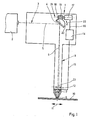
- a laser processing machine preferably of conventional form, has a cantilever-like machine part 1 and a laser device 2 which is mounted in a stationary manner, but which can preferably be aligned with respect to the machine part 1.
- a laser beam 3 emerges from this and is deflected by at least one deflecting mirror 4.
- the incoming beam part is 5 and the reflected part is 6 designated.
- the latter arrives at a focusing device 7 of a known type. It bundles the light beam and the bundled beam emerges via a nozzle 8 of the laser head 9. Then he reaches the workpiece 10, for example a metal sheet. He burns a hole in the latter.
- the laser beam can be aligned with the workpiece, for example, by attaching the laser device to the machine frame such that it can be tilted about two axes.
- the built-in deflection mirror can also be adjusted for certain laser devices. The adjustment opens a further possibility or additional possibility of the mirror or mirrors lying in the beam path between the laser device 2 and the nozzle 8. With an invisible laser beam, the adjustment is undoubtedly more difficult than with a visible one. In addition, it has hitherto been neither usual nor simple to check the correct position of the laser beam continuously or at any desired time while working with the machine. According to the invention, an improvement is now achieved in this regard by using at least one test device 12 (FIG. 1), but preferably at least two such test devices (FIGS.
- the beam path of the laser beam You can determine the deviation of the laser beam or the part of the laser beam that it can detect from a target position and convert this measurement result into a usable signal.
- This can either be placed on a display device or, preferably, on a computer 14.
- a connection between the latter and the or each test device is denoted by 15 in FIG. 1.
- the computer 14 is connected to one or two servomotors for the associated deflecting mirror.
- the deflecting mirror 4 is rotatable about an axis 18 perpendicular to the image plane.
- both this axis and the drive 21 for the mirror 4, which consists of a worm 19 and a worm wheel 20, are only to be understood symbolically and can be designed in another suitable manner.
- only one servomotor 17 and only one drive 21 are shown in FIG. 1 for the sake of clarity.
- the mirror is also one in the leaf plane horizontal second axis extending perpendicular to the axis 18 and therefore the computer 14 is also connected in a manner not shown via the line 16 to a second servomotor which can drive a second drive for the mirror 4.
- the beam can be aligned in the longitudinal and transverse directions as a function of an X and Y deviation of the actual position of the beam from a desired position.
- the pivoting of the mirror 4 about the axis 18 is symbolized by the double arrow 22.
- the target position of the laser beam is shown with dash-dotted lines and the actual position with dashed lines.
- the deviations which are for example in the minute range, are exaggerated.
- the test device 12 is symbolically drawn as a perforated disk, but this does not mean that it must have such a shape and design. How it is designed depends in particular on the nature and intensity of the beam. A center or at least a central region is expediently assigned to the desired position of the beam. In this middle there is also a coordinate zero point of a coordinate system.
- the beam of the actual position to be corrected deviates from this zero point in the X and Y directions by an amount to be determined by the test device.
- These two amounts are each preferably ge via a computer either to a display device for X and Y deviation or, advantageously, to corresponding actuators for X and Y correction movement give. If the values are only displayed, they can be read off and operated accordingly for tilting devices for the mirror. The deviation of the actual position from the target position of the beam is symbolized, for example in the X direction in FIG. 1, to a greatly exaggerated extent by the amount 23.
- the figures 2 and 3 show two different possibilities of assigning two test devices 12 and 13 to two deflecting mirrors 4 and 24. If the beam part 25 in FIG. 2 deviates from the desired position, then when the deflecting mirror 4 is automatically adjusted, the test device 12 effects its setting in Sense of the double arrows. 26 and 27. Analogously, the test device 13 causes the deflection mirror 24 to be adjusted in the sense of the double arrows 28 and 29, whereby of course only one rotary movement in one direction of the double arrow is required. The latter is only intended to indicate the possible rotating or tilting movements in the opposite sense. With the test device 13, the beam part 30 is monitored or its beam position is determined.
- test device 13 now causes the mirror 24 to be adjusted because the actual position of the beam part 30 deviates from the desired position, this mirror adjustment naturally has an effect on the course of the beam part 25. For this reason, all deviations must first be recorded and processed in a computer. This then takes the emergency into account agile adjustment movements of the two mirrors 4 and 24 taking into account the reaction of the mirror adjustment 24 on the beam part 25, so that the beam parts 25 and 30 assume a correct position at the end of the alignment movements of both mirrors.
- FIG. 3 shows, it is entirely possible to arrange two test devices 12 and 13, which are arranged at a distance from one another, between the deflecting mirror 4 and the focusing device 7, the testing device 12 controlling the deflecting mirror 4 and the testing device 13 controlling the deflecting mirror 24.
- the embodiment according to FIG. 3 enables a somewhat more compact design and this applies in particular if the deflection mirror 4, the two test devices 12 and 13 and the focusing device 7 with the nozzle 8 are accommodated in a common laser head 9.
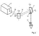
- FIG. 4 shows a laser device 2 designed as a double device.
- a main beam 31 and an auxiliary beam 32 emerge from this in absolute parallel position.
- the auxiliary beam 32 is preferably considerably weaker than the main beam 31 and, in contrast to the main beam, is also a visible laser beam.
- the two P are assigned rüfvorraumen 12 and 13 to the auxiliary beam, their arrangement may be in accordance with the scheme of Fig. 2 or FIG. 3. Due to the lower intensity, the load on the test devices is lower than in a review of the main beam.
- an alignment of the two mirrors 4 and 24 automatically results in a correct position of the main beam on the basis of a check of the position of the auxiliary beam because, as said, both leave the laser device 2 in parallel.
- a main beam and an auxiliary beam emerge from the laser device 2.
- an embodiment with only a single laser beam 3 is described below.
- the laser beam 3 emerging directly from the laser device 2 strikes a first deflecting mirror 33 of a holding device 35 for the laser head 9.
- the beam part located between the laser device 2 and this mirror 33 is denoted by 36.
- the laser beam is deflected by 90 ° at both mirrors, once in one horizontal and secondly in a vertical plane. It is easy to see that a displacement of the holding device 35 in the direction of the double arrow 38, i.e. in the longitudinal direction of the beam part 36, causes a displacement of the beam part 39 between the last deflecting mirror 34 and the workpiece 10 parallel to itself, so that the laser beam slits burns in this workpiece, which runs parallel to the beam part 36.
- the laser head 9 is mounted displaceably in the direction of the double arrow 40 on the holding device 35. This direction runs parallel to the beam part 37. Accordingly, when the holding device 35 is stationary and the laser head 9 is displaced on the holding device 35 in the direction of arrow 41 or in the opposite direction, the beam part 39 is displaced parallel to itself in the sense of the double arrow 40 the holding device 35 in the sense of the double arrow 38 is achieved by this displacement of the laser head along the longitudinal axis of the holding device 35 a displacement of the beam part 39 in the sense of the double arrow 40, so that a longitudinal slot can be burned into the workpiece 10 in this direction.
- the beam part 39 can be displaced parallel to itself in the X and Y directions and any contour can thereby be burned out of the workpiece 10.
- the laser head 9 is pivotally mounted on the holding device 35 about an axis parallel to or coincident with the beam part 37 in the sense of the double arrow 42, the pivot plane running through the Y axis and being perpendicular to the plane of the workpiece 10, so one can Instead of flat workpieces or sheets 10, also work on workpieces that are bent or curved in this pivoting direction.
- the deflecting mirrors 33 and 34 correspond to the principle according to the mirrors 24 and 4 of FIGS. 2 and 3, so that the laser beam of this machine can be checked for correct position in the manner described above by at least one or two test devices or the necessary corrections of the mirror positions can be carried out.
- the beam monitoring is checked continuously or at a predetermined time, for example periodically, and corrected if necessary.
- FIGS. 6 and 7 show how the beam part 25 is brought into the desired position by changing the mirrors 4 and 24, respectively. In FIG. 6 this is done by two tilts about mutually perpendicular axes on both mirrors 4 and 24, in FIG. 7 by two tilts and by the displacement of the mirror 4 along the double arrow 43 and of the mirror 24 along the double arrow 44.
Landscapes
- Physics & Mathematics (AREA)
- Optics & Photonics (AREA)
- Engineering & Computer Science (AREA)
- Plasma & Fusion (AREA)
- Mechanical Engineering (AREA)
- Laser Beam Processing (AREA)
Applications Claiming Priority (2)
| Application Number | Priority Date | Filing Date | Title |
|---|---|---|---|
| DE3339318 | 1983-10-29 | ||
| DE3339318A DE3339318C2 (de) | 1983-10-29 | 1983-10-29 | Laser-Bearbeitungsmaschine |
Publications (2)
| Publication Number | Publication Date |
|---|---|
| EP0147525A1 true EP0147525A1 (fr) | 1985-07-10 |
| EP0147525B1 EP0147525B1 (fr) | 1988-01-07 |
Family
ID=6213055
Family Applications (1)
| Application Number | Title | Priority Date | Filing Date |
|---|---|---|---|
| EP84109857A Expired EP0147525B1 (fr) | 1983-10-29 | 1984-08-16 | Machine de traitement par laser |
Country Status (4)
| Country | Link |
|---|---|
| US (1) | US4675501A (fr) |
| EP (1) | EP0147525B1 (fr) |
| JP (1) | JPS60111789A (fr) |
| DE (1) | DE3339318C2 (fr) |
Cited By (6)
| Publication number | Priority date | Publication date | Assignee | Title |
|---|---|---|---|---|
| EP0266764A2 (fr) * | 1986-11-07 | 1988-05-11 | Fried. Krupp Gesellschaft mit beschränkter Haftung | Méthode et dispositif de guidage d'un rayon laser de puissance le long d'un joint |
| EP0339402A1 (fr) * | 1988-04-25 | 1989-11-02 | Electro Scientific Industries, Inc. | Système de positionnement d'un faisceau lumineux |
| GB2233784A (en) * | 1989-07-04 | 1991-01-16 | Renishaw Plc | Laser beam deflector comprising two reflectors |
| EP0468937A2 (fr) * | 1990-07-27 | 1992-01-29 | PRIMA INDUSTRIE S.p.A. | Equipement pour l'ajustement de l'alignement d'un rayon laser le long d'une ligne de référence donnée |
| GB2329724A (en) * | 1997-09-24 | 1999-03-31 | Samsung Electronics Co Ltd | A view selecting apparatus for an X-ray inspection system |
| CN102658423A (zh) * | 2010-07-30 | 2012-09-12 | 高洪波 | 智能化视觉定位+激光束同轴高精度实时激光加工系统 |
Families Citing this family (51)
| Publication number | Priority date | Publication date | Assignee | Title |
|---|---|---|---|---|
| JPS632581A (ja) * | 1986-06-19 | 1988-01-07 | Nikon Corp | レ−ザビ−ム調整装置 |
| US4773019A (en) * | 1986-04-24 | 1988-09-20 | Mechanical Technology Incorporated | Microprocessor laser control system for multiplane balancing of rotors |
| DE3623409A1 (de) * | 1986-07-11 | 1988-01-21 | Bias Forschung & Entwicklung | Verfahren zur ueberwachung des bearbeitungsprozesses mit einer hochleistungsenergiequelle, insbesondere einem laser, und bearbeitungsoptik zur durchfuehrung desselben |
| JPH0666500B2 (ja) * | 1986-09-04 | 1994-08-24 | フアナツク株式会社 | ガスレ−ザ装置 |
| US5177806A (en) * | 1986-12-05 | 1993-01-05 | E. I. Du Pont De Nemours And Company | Optical fiber feedthrough |
| US5222170A (en) * | 1987-04-03 | 1993-06-22 | Bt&D Technologies Ltd. | Optical fiber device fabrication |
| US4907881A (en) * | 1988-03-10 | 1990-03-13 | The United States Of America As Represented By The United States Department Of Energy | Precision alignment device |
| US4859075A (en) * | 1988-03-14 | 1989-08-22 | Directed Energy, Inc. | Laser thermal testing method and system for use with a fire alarm system |
| US4855564A (en) * | 1988-05-23 | 1989-08-08 | Westinghouse Electric Corp. | Laser beam alignment and transport system |
| FR2662383B1 (fr) * | 1990-05-28 | 1994-12-23 | Snecma | Dispositif d'amenee d'un faisceau laser a une piece a usiner. |
| WO1992008569A1 (fr) * | 1990-11-14 | 1992-05-29 | Fanuc Ltd | Procede de reglage d'axe optique pour robot a laser et systeme prevu a cet effet |
| US5536916A (en) * | 1994-09-30 | 1996-07-16 | Sanyo Machine Works, Ltd. | Method for performing automatic alignment-adjustment of laser robot and the device |
| US6191382B1 (en) | 1998-04-02 | 2001-02-20 | Avery Dennison Corporation | Dynamic laser cutting apparatus |
| KR20010081612A (ko) * | 2000-02-17 | 2001-08-29 | 성규동 | 이동식 광헤드를 가지는 레이저 장치의 광 전송시스템 |
| US6483071B1 (en) | 2000-05-16 | 2002-11-19 | General Scanning Inc. | Method and system for precisely positioning a waist of a material-processing laser beam to process microstructures within a laser-processing site |
| DE10024079A1 (de) * | 2000-05-17 | 2001-11-22 | Asclepion Meditec Ag | Verfahren und Vorrichtung zur Kontrolle der Energie und/oder Position eines gepulsten und gescannten Laserstrahles |
| US6423928B1 (en) | 2000-10-12 | 2002-07-23 | Ase Americas, Inc. | Gas assisted laser cutting of thin and fragile materials |
| US6528762B2 (en) | 2001-02-12 | 2003-03-04 | W. A. Whitney Co. | Laser beam position control apparatus for a CNC laser equipped machine tool |
| US6972268B2 (en) * | 2001-03-29 | 2005-12-06 | Gsi Lumonics Corporation | Methods and systems for processing a device, methods and systems for modeling same and the device |
| US20030222209A1 (en) * | 2002-06-04 | 2003-12-04 | Mitchell Phillip V. | Compact, large angle beam stabilization module |
| US7880116B2 (en) * | 2003-03-18 | 2011-02-01 | Loma Linda University Medical Center | Laser head for irradiation and removal of material from a surface of a structure |
| US7286223B2 (en) * | 2003-03-18 | 2007-10-23 | Loma Linda University Medical Center | Method and apparatus for detecting embedded rebar within an interaction region of a structure irradiated with laser light |
| US7038166B2 (en) * | 2003-03-18 | 2006-05-02 | Loma Linda University Medical Center | Containment plenum for laser irradiation and removal of material from a surface of a structure |
| US7379483B2 (en) * | 2003-03-18 | 2008-05-27 | Loma Linda University Medical Center | Method and apparatus for material processing |
| US7060932B2 (en) * | 2003-03-18 | 2006-06-13 | Loma Linda University Medical Center | Method and apparatus for material processing |
| US7057134B2 (en) * | 2003-03-18 | 2006-06-06 | Loma Linda University Medical Center | Laser manipulation system for controllably moving a laser head for irradiation and removal of material from a surface of a structure |
| DE102004063692B3 (de) * | 2004-12-28 | 2006-05-11 | Georg-August-Universität Göttingen | Positioniereinrichtung |
| US7676061B2 (en) * | 2006-05-02 | 2010-03-09 | Telesis Technologies, Inc. | Laser safety system |
| DE102006055050A1 (de) | 2006-11-22 | 2008-05-29 | Eos Gmbh Electro Optical Systems | Vorrichtung zum schichtweisen Herstellen eines dreidimensionalen Objekts und Verfahren zum Justieren eines Optiksystems von dieser |
| DE102008030783B3 (de) * | 2008-06-28 | 2009-08-13 | Trumpf Werkzeugmaschinen Gmbh + Co. Kg | Verfahren zum Laserstrahlschrägschneiden und Laserbearbeitungsmaschine |
| US8892222B2 (en) * | 2009-07-17 | 2014-11-18 | Diversitech Equipment And Sales (1984) Ltd. | Fume extraction system with automatic fume hood positioning |
| JP5456510B2 (ja) * | 2010-02-23 | 2014-04-02 | 株式会社ディスコ | レーザ加工装置 |
| US20130200053A1 (en) * | 2010-04-13 | 2013-08-08 | National Research Council Of Canada | Laser processing control method |
| EP2409808A1 (fr) * | 2010-07-22 | 2012-01-25 | Bystronic Laser AG | Machine de traitement au laser |
| US9289852B2 (en) | 2011-01-27 | 2016-03-22 | Bystronic Laser Ag | Laser processing machine, laser cutting machine, and method for adjusting a focused laser beam |
| WO2012101533A1 (fr) | 2011-01-27 | 2012-08-02 | Bystronic Laser Ag | Machine de traitement au laser, en particulier machine de coupe au laser, ainsi que procédé permettant de centrer un faisceau laser, en particulier un faisceau focalisé |
| DE102011005775B4 (de) * | 2011-03-18 | 2012-11-15 | Trumpf Werkzeugmaschinen Gmbh + Co. Kg | Detektor und Verfahren zum Erfassen einer Ausrichtung eines Laserstrahls in einer Laserbearbeitungsmaschine sowie Laserbearbeitungsmaschine |
| DE102011116974A1 (de) * | 2011-10-26 | 2013-05-02 | Vollmer Werke Maschinenfabrik Gmbh | Vorrichtung und Verfahren zum Herstellen einer Führungsfase an einem Werkstück, insbesondere an einem schneidenden Werkzeug |
| GB2498943A (en) * | 2012-01-31 | 2013-08-07 | Ibm | Evaluating and optimizing a trajectory function |
| US10005154B2 (en) * | 2012-02-14 | 2018-06-26 | Murata Machinery, Ltd. | Laser processing machine |
| FI20135385L (fi) * | 2013-04-18 | 2014-10-19 | Cajo Tech Oy | Metallipintojen värimerkintä |
| DE102013215442A1 (de) * | 2013-08-06 | 2015-02-12 | Robert Bosch Gmbh | Vorrichtung zur Materialbearbeitung mit einem Laserstrahl |
| DE102013109479B3 (de) * | 2013-08-30 | 2014-09-18 | Rofin-Baasel Lasertech Gmbh & Co. Kg | Verfahren und Laseranordnung zum Bearbeiten eines Werkstücks mit einem gepulsten Laserstrahl |
| EP2883647B1 (fr) | 2013-12-12 | 2019-05-29 | Bystronic Laser AG | Procédé de configuration d'un dispositif d'usinage au laser |
| EP2894004B1 (fr) | 2014-01-08 | 2017-10-25 | Bystronic Laser AG | Dispositif de traitement laser avec une caméra et un mirroir mobile |
| EP2957378A1 (fr) * | 2014-06-16 | 2015-12-23 | Synova SA | Tête d'usinage pour coupler un fisceau laser et un faisceau de fluide avec une interface |
| JP6334074B1 (ja) * | 2017-05-23 | 2018-05-30 | 堺ディスプレイプロダクト株式会社 | 素子基板の製造方法およびレーザクリーニング装置 |
| KR102167313B1 (ko) * | 2018-08-01 | 2020-10-19 | (주)엠에스라인이엔지 | 레이저 에이머가 구비된 방사선 차폐장치 및 이를 장착한 엑스레이 촬영장치 |
| CN112692428A (zh) * | 2019-10-23 | 2021-04-23 | Nps株式会社 | 激光装置 |
| CN111872545B (zh) * | 2020-07-22 | 2022-05-06 | 江苏亚威艾欧斯激光科技有限公司 | 一种用于晶片标记的激光设备 |
| CN115245993A (zh) * | 2021-04-25 | 2022-10-28 | 昆山玛冀电子有限公司 | 线圈引线裁切机及裁切方法 |
Citations (4)
| Publication number | Priority date | Publication date | Assignee | Title |
|---|---|---|---|---|
| DE2947071A1 (de) * | 1978-12-27 | 1980-07-10 | Halle Feinmech Werke Veb | Anordnung zur praezisionsmaterialbearbeitung mittels laserstrahlen |
| US4327277A (en) * | 1978-08-24 | 1982-04-27 | Raytheon Company | Method for laser soldering |
| DE3134556A1 (de) * | 1980-09-02 | 1982-06-24 | Amada Co. Ltd., Isehara, Kanagawa | Vorrichtung zur ueberwachung der lageabweichung der optischen achse bei lasereinrichtungen |
| DE3228698A1 (de) * | 1981-08-14 | 1983-03-03 | General Electric Co., Schenectady, N.Y. | Verfahren und vorrichtung zum pruefen und steuern der position von loechern |
Family Cites Families (7)
| Publication number | Priority date | Publication date | Assignee | Title |
|---|---|---|---|---|
| US3619550A (en) * | 1969-09-25 | 1971-11-09 | Laser Systems Corp | Laser beam machine tool with beam manipulating apparatus |
| US3902036A (en) * | 1974-05-02 | 1975-08-26 | Western Electric Co | Control system using multiplexed laser beams |
| US4243867A (en) * | 1978-06-26 | 1981-01-06 | Caterpillar Tractor Co. | Apparatus for fusibly bonding a coating material to a metal article |
| JPS5577989A (en) * | 1978-12-11 | 1980-06-12 | Citizen Watch Co Ltd | Beam position detecting device in laser machine |
| JPS5641088A (en) * | 1979-09-12 | 1981-04-17 | Hitachi Ltd | Monitoring device for laser light axis |
| JPS57154389A (en) * | 1981-03-19 | 1982-09-24 | Toshiba Corp | Laser working device |
| US4417123A (en) * | 1981-07-06 | 1983-11-22 | The United States Of America As Represented By The Secretary Of The Navy | Laser formed video tube calibration markers |
-
1983
- 1983-10-29 DE DE3339318A patent/DE3339318C2/de not_active Expired - Fee Related
-
1984
- 1984-08-16 EP EP84109857A patent/EP0147525B1/fr not_active Expired
- 1984-10-22 US US06/663,239 patent/US4675501A/en not_active Expired - Lifetime
- 1984-10-29 JP JP59226031A patent/JPS60111789A/ja active Pending
Patent Citations (4)
| Publication number | Priority date | Publication date | Assignee | Title |
|---|---|---|---|---|
| US4327277A (en) * | 1978-08-24 | 1982-04-27 | Raytheon Company | Method for laser soldering |
| DE2947071A1 (de) * | 1978-12-27 | 1980-07-10 | Halle Feinmech Werke Veb | Anordnung zur praezisionsmaterialbearbeitung mittels laserstrahlen |
| DE3134556A1 (de) * | 1980-09-02 | 1982-06-24 | Amada Co. Ltd., Isehara, Kanagawa | Vorrichtung zur ueberwachung der lageabweichung der optischen achse bei lasereinrichtungen |
| DE3228698A1 (de) * | 1981-08-14 | 1983-03-03 | General Electric Co., Schenectady, N.Y. | Verfahren und vorrichtung zum pruefen und steuern der position von loechern |
Cited By (10)
| Publication number | Priority date | Publication date | Assignee | Title |
|---|---|---|---|---|
| EP0266764A2 (fr) * | 1986-11-07 | 1988-05-11 | Fried. Krupp Gesellschaft mit beschränkter Haftung | Méthode et dispositif de guidage d'un rayon laser de puissance le long d'un joint |
| EP0266764A3 (fr) * | 1986-11-07 | 1990-05-16 | Fried. Krupp Gesellschaft mit beschränkter Haftung | Méthode et dispositif de guidage d'un rayon laser de puissance le long d'un joint |
| EP0339402A1 (fr) * | 1988-04-25 | 1989-11-02 | Electro Scientific Industries, Inc. | Système de positionnement d'un faisceau lumineux |
| US4941082A (en) * | 1988-04-25 | 1990-07-10 | Electro Scientific Industries, Inc. | Light beam positioning system |
| GB2233784A (en) * | 1989-07-04 | 1991-01-16 | Renishaw Plc | Laser beam deflector comprising two reflectors |
| GB2233784B (en) * | 1989-07-04 | 1993-08-25 | Renishaw Plc | Beam deflector |
| EP0468937A2 (fr) * | 1990-07-27 | 1992-01-29 | PRIMA INDUSTRIE S.p.A. | Equipement pour l'ajustement de l'alignement d'un rayon laser le long d'une ligne de référence donnée |
| EP0468937A3 (en) * | 1990-07-27 | 1992-04-22 | Prima Industrie S.P.A. | An adjustment device for aligning a laser beam along a predetermined reference line |
| GB2329724A (en) * | 1997-09-24 | 1999-03-31 | Samsung Electronics Co Ltd | A view selecting apparatus for an X-ray inspection system |
| CN102658423A (zh) * | 2010-07-30 | 2012-09-12 | 高洪波 | 智能化视觉定位+激光束同轴高精度实时激光加工系统 |
Also Published As
| Publication number | Publication date |
|---|---|
| EP0147525B1 (fr) | 1988-01-07 |
| US4675501A (en) | 1987-06-23 |
| DE3339318C2 (de) | 1995-05-24 |
| JPS60111789A (ja) | 1985-06-18 |
| DE3339318A1 (de) | 1985-05-09 |
Similar Documents
| Publication | Publication Date | Title |
|---|---|---|
| EP0147525A1 (fr) | Machine de traitement par laser | |
| EP1773534B2 (fr) | Dispositif laser et procédé de fonctionnement | |
| EP0284921B1 (fr) | Dispositif pour conduir des rayons optiques | |
| DE19634190A1 (de) | Mehrkopf-Lasergravuranlage | |
| DE2933700A1 (de) | Werkzeugmaschine mit schmelzschneideinrichtung | |
| DE10045191A1 (de) | Verfahren und Vorrichtung zur Echtzeitsteuerung der Strahlcharakteristiken bei einer mit einem Laser ausgerüsteten Werkzeugmaschine | |
| DE2600007C2 (de) | Maschine zum Entfernen von Material von einem plattenförmigen, gewölbten Werkstück | |
| DE102005035286A1 (de) | Schutzeinrichtung für Maschinen, wie Abkantpressen, Schneidemaschinen, Stanzmaschinen oder dergleichen | |
| AT390025B (de) | Vorrichtung zum herstellen prismatischer oder pyramidenstumpffoermiger balken | |
| EP2846966A1 (fr) | Centre de transfert destiné à usiner au moins une pièce par enlèvement de matière, comprenant un système de compensation de position | |
| DE69909977T2 (de) | Vorrichtung zum Stumpf-Laserschweissen von Blechen (vorbestimmten Zuschnitten), die magnetische Rollen hat um die Bleche nach der Schweissposition zu bewegen und die aktive Klemmen hat, um die Bleche zu klemmen | |
| DE2505774C3 (de) | Justiervorrichtung für eine Laseranordnung aus einem Leistungslaser und einem Justierlaser | |
| EP1742307B1 (fr) | Dispositif pour le contrôle de la polarisation d'un faisceau laser | |
| EP0417623A1 (fr) | Dispositif de réglage des bords | |
| EP2648666A1 (fr) | Dispositif laser destiné notamment à la chirurgie laser ophtalmologique | |
| EP1815953B1 (fr) | Butée pour une machine de traitement | |
| DE3915855C2 (fr) | ||
| DE102018201416A1 (de) | Vorrichtung zum Fügen, insbesondere Laserschweißen, zweier Bauteile und Betriebsverfahren für eine solche Fügevorrichtung | |
| DE2326024C2 (de) | Vorrichtung zum Schneiden von Platten, Folien oder dergleichen | |
| DE3444045C2 (de) | Führungsvorrichtung für einen Laserstrahl zur dreidimensionalen Werkstückbearbeitung | |
| DE10258553A1 (de) | Vorrichtung zum Schneiden von Präparaten mit einer automatischen Anstellvorrichtung | |
| DE202022001374U1 (de) | Laser-Schweißkopf | |
| DE102022002164A1 (de) | Laser-Schweißkopf | |
| EP3184229A1 (fr) | Dispositif et procédé de soudage | |
| DE598080C (de) | Maschine zum selbsttaetigen Bearbeiten von Kurvenscheiben und Kurventrommeln durch einen von einem elektrischen Taster gesteuerten Fraeser |
Legal Events
| Date | Code | Title | Description |
|---|---|---|---|
| PUAI | Public reference made under article 153(3) epc to a published international application that has entered the european phase |
Free format text: ORIGINAL CODE: 0009012 |
|
| AK | Designated contracting states |
Designated state(s): CH FR GB IT LI |
|
| 17P | Request for examination filed |
Effective date: 19850531 |
|
| 17Q | First examination report despatched |
Effective date: 19860604 |
|
| GRAA | (expected) grant |
Free format text: ORIGINAL CODE: 0009210 |
|
| ITF | It: translation for a ep patent filed |
Owner name: DE DOMINICIS & MAYER S.R.L. |
|
| AK | Designated contracting states |
Kind code of ref document: B1 Designated state(s): CH FR GB IT LI |
|
| GBT | Gb: translation of ep patent filed (gb section 77(6)(a)/1977) | ||
| ET | Fr: translation filed | ||
| PLBE | No opposition filed within time limit |
Free format text: ORIGINAL CODE: 0009261 |
|
| STAA | Information on the status of an ep patent application or granted ep patent |
Free format text: STATUS: NO OPPOSITION FILED WITHIN TIME LIMIT |
|
| 26N | No opposition filed | ||
| ITTA | It: last paid annual fee | ||
| PGFP | Annual fee paid to national office [announced via postgrant information from national office to epo] |
Ref country code: FR Payment date: 19930723 Year of fee payment: 10 |
|
| PGFP | Annual fee paid to national office [announced via postgrant information from national office to epo] |
Ref country code: GB Payment date: 19930726 Year of fee payment: 10 |
|
| PG25 | Lapsed in a contracting state [announced via postgrant information from national office to epo] |
Ref country code: GB Effective date: 19940816 |
|
| GBPC | Gb: european patent ceased through non-payment of renewal fee |
Effective date: 19940816 |
|
| PG25 | Lapsed in a contracting state [announced via postgrant information from national office to epo] |
Ref country code: FR Effective date: 19950428 |
|
| REG | Reference to a national code |
Ref country code: FR Ref legal event code: ST |
|
| PGFP | Annual fee paid to national office [announced via postgrant information from national office to epo] |
Ref country code: CH Payment date: 20010628 Year of fee payment: 18 |
|
| PG25 | Lapsed in a contracting state [announced via postgrant information from national office to epo] |
Ref country code: LI Free format text: LAPSE BECAUSE OF NON-PAYMENT OF DUE FEES Effective date: 20020831 Ref country code: CH Free format text: LAPSE BECAUSE OF NON-PAYMENT OF DUE FEES Effective date: 20020831 |
|
| REG | Reference to a national code |
Ref country code: CH Ref legal event code: PL |