EP2894004B1 - Dispositif de traitement laser avec une caméra et un mirroir mobile - Google Patents
Dispositif de traitement laser avec une caméra et un mirroir mobile Download PDFInfo
- Publication number
- EP2894004B1 EP2894004B1 EP14150430.8A EP14150430A EP2894004B1 EP 2894004 B1 EP2894004 B1 EP 2894004B1 EP 14150430 A EP14150430 A EP 14150430A EP 2894004 B1 EP2894004 B1 EP 2894004B1
- Authority
- EP
- European Patent Office
- Prior art keywords
- laser
- camera
- mirror
- laser beam
- laser machining
- Prior art date
- Legal status (The legal status is an assumption and is not a legal conclusion. Google has not performed a legal analysis and makes no representation as to the accuracy of the status listed.)
- Active
Links
- 238000003754 machining Methods 0.000 title claims description 32
- 238000000034 method Methods 0.000 claims description 25
- 238000011156 evaluation Methods 0.000 claims description 22
- 230000001681 protective effect Effects 0.000 claims description 22
- 239000011521 glass Substances 0.000 claims description 21
- 230000003287 optical effect Effects 0.000 claims description 15
- 238000011109 contamination Methods 0.000 claims description 11
- 238000003384 imaging method Methods 0.000 claims description 8
- 238000003698 laser cutting Methods 0.000 claims description 7
- 238000011157 data evaluation Methods 0.000 claims description 4
- 238000009826 distribution Methods 0.000 claims description 3
- 238000003708 edge detection Methods 0.000 claims description 3
- 230000002093 peripheral effect Effects 0.000 claims description 3
- 238000001429 visible spectrum Methods 0.000 claims description 3
- 238000004891 communication Methods 0.000 claims 3
- 230000000694 effects Effects 0.000 claims 1
- 239000005336 safety glass Substances 0.000 claims 1
- 238000012545 processing Methods 0.000 description 57
- 238000012544 monitoring process Methods 0.000 description 6
- 238000005520 cutting process Methods 0.000 description 4
- 230000001419 dependent effect Effects 0.000 description 3
- 238000001514 detection method Methods 0.000 description 3
- 238000003672 processing method Methods 0.000 description 3
- 230000003044 adaptive effect Effects 0.000 description 2
- 239000000853 adhesive Substances 0.000 description 1
- 230000001070 adhesive effect Effects 0.000 description 1
- 238000013461 design Methods 0.000 description 1
- 238000011161 development Methods 0.000 description 1
- 230000018109 developmental process Effects 0.000 description 1
- 238000005286 illumination Methods 0.000 description 1
- 239000000463 material Substances 0.000 description 1
- 230000000149 penetrating effect Effects 0.000 description 1
- 230000005855 radiation Effects 0.000 description 1
- 230000003595 spectral effect Effects 0.000 description 1
- 238000012360 testing method Methods 0.000 description 1
- 238000011144 upstream manufacturing Methods 0.000 description 1
- 230000000007 visual effect Effects 0.000 description 1
Images

Classifications
-
- B—PERFORMING OPERATIONS; TRANSPORTING
- B23—MACHINE TOOLS; METAL-WORKING NOT OTHERWISE PROVIDED FOR
- B23K—SOLDERING OR UNSOLDERING; WELDING; CLADDING OR PLATING BY SOLDERING OR WELDING; CUTTING BY APPLYING HEAT LOCALLY, e.g. FLAME CUTTING; WORKING BY LASER BEAM
- B23K26/00—Working by laser beam, e.g. welding, cutting or boring
- B23K26/02—Positioning or observing the workpiece, e.g. with respect to the point of impact; Aligning, aiming or focusing the laser beam
- B23K26/03—Observing, e.g. monitoring, the workpiece
-
- B—PERFORMING OPERATIONS; TRANSPORTING
- B23—MACHINE TOOLS; METAL-WORKING NOT OTHERWISE PROVIDED FOR
- B23K—SOLDERING OR UNSOLDERING; WELDING; CLADDING OR PLATING BY SOLDERING OR WELDING; CUTTING BY APPLYING HEAT LOCALLY, e.g. FLAME CUTTING; WORKING BY LASER BEAM
- B23K26/00—Working by laser beam, e.g. welding, cutting or boring
- B23K26/02—Positioning or observing the workpiece, e.g. with respect to the point of impact; Aligning, aiming or focusing the laser beam
- B23K26/04—Automatically aligning, aiming or focusing the laser beam, e.g. using the back-scattered light
- B23K26/042—Automatically aligning the laser beam
- B23K26/043—Automatically aligning the laser beam along the beam path, i.e. alignment of laser beam axis relative to laser beam apparatus
-
- B—PERFORMING OPERATIONS; TRANSPORTING
- B23—MACHINE TOOLS; METAL-WORKING NOT OTHERWISE PROVIDED FOR
- B23K—SOLDERING OR UNSOLDERING; WELDING; CLADDING OR PLATING BY SOLDERING OR WELDING; CUTTING BY APPLYING HEAT LOCALLY, e.g. FLAME CUTTING; WORKING BY LASER BEAM
- B23K26/00—Working by laser beam, e.g. welding, cutting or boring
- B23K26/14—Working by laser beam, e.g. welding, cutting or boring using a fluid stream, e.g. a jet of gas, in conjunction with the laser beam; Nozzles therefor
- B23K26/1462—Nozzles; Features related to nozzles
-
- B—PERFORMING OPERATIONS; TRANSPORTING
- B23—MACHINE TOOLS; METAL-WORKING NOT OTHERWISE PROVIDED FOR
- B23K—SOLDERING OR UNSOLDERING; WELDING; CLADDING OR PLATING BY SOLDERING OR WELDING; CUTTING BY APPLYING HEAT LOCALLY, e.g. FLAME CUTTING; WORKING BY LASER BEAM
- B23K26/00—Working by laser beam, e.g. welding, cutting or boring
- B23K26/36—Removing material
- B23K26/38—Removing material by boring or cutting
Definitions
- the invention relates to a laser processing apparatus according to the preamble of claim 1 and to a laser processing method according to the preamble of claim 6 (see, for example, US Pat. JP H10 249 566 A ).
- the JP H04 118193 A discloses the detection of the degree of soiling of the protective glass by means of an image sensor or a camera. This camera is positioned above a stationary, rigid deflection mirror for the working laser beam and in line with this mirror and the exit nozzle.
- the JP H10 249566 A discloses an arrangement of two deflection mirrors for the working laser beam, which both mirrors must be moved under the control of a control device in order to adjust the working laser beam with respect to the exit nozzle.
- the position of the laser beam is determined via a camera within the machining head and the adjustment is effected by means of movement of both mirrors.
- the camera is positioned between the last deflection mirror and an optical element above the outlet nozzle.
- the EP1728582A1 discloses a device for detecting changes in the laser beam.
- a sensor for detecting laser beam changes is arranged in front of the laser processing head.
- a controller evaluates the data from the sensor and drives an adaptive mirror. With the in-process determined data, the adaptive mirror 2, according to predetermined data, adjusted.
- the control unit can record the measured values of the laser beam and compare them with nominal values. With such a system, a change in the diameter of the laser beam between the output mirror of the laser and the processing head of the laser processing machine can be compensated.
- the US5449882 discloses a laser processing system in which a beam splitter is adjustable by means of piezoelectric drive.
- a microscope head can be focused on the object to be processed to position the initial position of the laser spot on the object.
- the control of the piezoelectric drive is performed by the operator by means of a joystick.
- the EP0147525B1 discloses a laser processing apparatus in which an automatic adjustment of deflecting mirrors takes place as a function of the deviation of the beam position from a desired value.
- a test device is provided which is located immediately above the outlet nozzle.
- This type of detector is on the one hand able to detect a laser beam, even if it belongs to the non-visible area, without taking self-damage by the laser beam and the deviation of the actual value of a target value, ie the desired normal position of the laser beam, in a suitable display and / or adjustment value for an adjustment of the one or more controllable mirror converts.
- the EP0154866B1 discloses a laser processing machine in which the offset or angle changes of the laser beam is corrected via controllable adjusting mirrors. To detect the offset or angle changes position-sensitive, photoelectric detectors are mentioned. In this case, a portion of the laser light is reflected in the direction of the detector or a pilot laser used.
- the WO2012000648A1 discloses a 'closed loop' controller for a laser processing operation using a camera.
- the EP1716963B1 discloses a laser material processing with a pivotable mirror which deflects the laser beam.
- the DE102011004117A1 discloses a laser processing machine with a partially transmissive mirror behind which a beam path is guided in the direction of a camera.
- the camera and the evaluation device connected thereto are used for process monitoring, in particular detection of a tilt angle of a workpiece part or faulty machining.
- the EP2216129A1 discloses a system for focus position monitoring. In this case, a lens is driven. It is also known to position the laser beam via a manual beam adjustment. The actual position of the laser beam is assessed today on the basis of the position of a laser bullet hole on a temporarily attached adhesive strip on the outlet nozzle.
- the disadvantages resulting from the prior art are that a reliable imaging of the laser beam impinging on the workpiece, in particular in relation to the outlet nozzle, is not possible. In other systems, it is left to the operator to position the laser beam by hand.
- the prior art solutions using a detector are complex in structure and susceptible to contamination.
- a disadvantage of many of these solutions is also that a detection of the laser beam is outside the laser processing head, so that lateral position shifts of the laser spot on the workpiece are not registered at all.
- the object of the present invention is thus to eliminate these disadvantages and to provide a laser processing apparatus with which a reliable imaging of the outlet nozzle or of the outlet nozzle upstream of transparent components can be achieved.
- an automation of the laser machining process is to be ensured, which leads to an optimal workpiece machining. It is to be prevented that errors or inadmissible operating states, which are assigned to the area of the laser processing head, lead to a qualitatively inferior processing.
- a laser processing apparatus for processing a workpiece with a laser beam, in particular a laser cutting machine, comprising a laser processing head with a laser exit nozzle, a defined within the laser processing head laser beam path, a single arranged in the laser beam path and movable mirror for deflecting the laser beam to the outlet nozzle, and at least one imaging camera, wherein the camera beam path directed from the inside to the outlet nozzle and the camera is communicatively connected to an image data evaluation device.
- the mirror is movable and communicatively connected to a drive for moving the mirror, whereby a control device is also communicatively connected to the drive of the one mirror, wherein the control device is designed to drive the drive as a function of the evaluation of the image data recorded by the camera the mirror to be automatically controlled, whereby a predetermined, in particular centered, alignment of the laser beam laterally in the XY plane with respect to the outlet nozzle is achievable.
- the mirror is a wavelength-selective mirror, which is reflective for the laser beam in the laser beam path and permeable to at least one wavelength range of the visible spectrum, and that the camera beam path passes through the mirror, wherein preferably the laser beam path and the camera Overlay the beam path in the section between the mirror and the outlet nozzle.
- the advantage of the invention is that the actual position of the laser beam on the workpiece can be determined exactly by an image acquisition.
- the control device can be used to correct the jet position by pivoting the mirror, which results in automatic regulation.
- This arrangement also allows the decoupling of the laser beam from that received by the camera (visible) light.
- the images are not affected by the laser beam fed into the laser processing head, resulting in high-quality images that are accessible for reliable evaluation.
- the laser processing head e.g. Cutting head
- the laser processing head is preferably equipped with a motor-operated, dynamic pivoting mirror. This allows the laser beam to be adjusted laterally in the X / Y plane, relative to the exit nozzle.
- the camera is preferably arranged inside the laser processing head. In combination with the camera, an automatic beam adjustment, in particular beam centering, can be realized relative to the outlet nozzle opening. By pivoting or moving the mirror through the mirror drive controlled by the control device, the laser beam can be exactly aligned relative to the outlet nozzle.
- the evaluation device and the control device are also communicatively connected with each other or form a structural unit anyway.
- the mirror is preferably transmissive in the visual spectral region (preferred exception: wavelength for a pilot laser is reflected) and the camera is behind the mirror.
- the lateral beam position is checked with the camera and readjusted if necessary. This allows online control of the jet position to the outlet nozzle.
- a loss of the nozzle can also be controlled. There is also the possibility - especially in combination with an interior lighting - to determine the outlet nozzle type (various geometric shapes).
- a focusable camera system it is also possible to monitor the protective glass or optical components in the camera beam path. It is possible to detect the presence and the degree of pollution.
- Known systems determine the degree of contamination on the basis of the scattered radiation, based on the can not be determined whether a pollution is present in the middle (critical) or rather on the edge (non-critical).
- a camera system can determine the size and location of the contamination and deduce whether this is critical or uncritical for the laser processing operation.
- the lateral beam position is checked and readjusted during or before piercing and / or cutting with the camera. This allows online control of the jet position to the nozzle.
- the camera is designed to receive visible light and is preferably arranged above the outlet nozzle opening and behind the mirror.
- a preferred embodiment is characterized in that the camera is arranged above the mirror, preferably in a line with the outlet nozzle opening and the mirror. Here is the mirror between the outlet nozzle and the camera. The camera beam path is thus not deflected, resulting in a compact design.
- the camera is arranged within the laser processing head, ie the camera beam path does not have to be led out of the head.
- the mirror and drive is located within the laser processing head.
- the laser processing head thus represents a compact module with far more integrated functionality than is the case with known systems.
- a preferred embodiment is characterized in that the drive of the mirror is a dynamic drive whose dynamics is preferably at least 1 kHz, more preferably at least 2 kHz. This allows for real-time tracking of the laser beam, allowing for high quality cuts.
- the drive is preferably a piezoelectric drive.
- a preferred embodiment is characterized in that the camera comprises a focusing device, wherein preferably the camera with the focusing device is sharply adjustable both on the region of the outlet nozzle and on the region of a protective glass arranged behind the outlet nozzle.
- the laser processing device comprises at least two cameras, wherein one camera is focused on the region of the outlet nozzle and the other camera on the region of a protective glass arranged behind the outlet nozzle.
- a beam splitter can be arranged in at least one camera beam path or in the beam paths of the two cameras.
- a laser processing method for processing a workpiece with a laser beam.
- a laser processing device (in particular according to one of the preceding embodiments) comprising a laser processing head with a laser exit nozzle, a laser beam path defined within the laser processing head and an imaging camera, the camera beam path directed from the inside onto the exit nozzle is.
- At least one image is taken with the camera and evaluated with an evaluation device, wherein at least the position of the laser beam with respect to the outlet nozzle opening is determined on the basis of the image data.
- a single arranged in the laser beam path and movable mirror for deflecting the laser beam is automatically moved to the outlet nozzle , whereby a predetermined, in particular centered or otherwise, alignment of the laser beam is achieved laterally in the XY plane with respect to the outlet nozzle.
- the image taken by the camera comprises the contour of the outlet nozzle opening, and in dependence on a deviation of the actual position of the laser beam from a desired position of the laser beam with respect to the outlet nozzle opening, the drive of the mirror is controlled by the control device such that the laser beam assumes the target position.
- this enables automatic monitoring which, in the case of an undesired state, an error, a positional deviation, leads to an action of the control device, ie an automatic reaction of the system takes place.
- the exit nozzle opening represents a reliable reference contained in the same image as the laser beam (spot) impinging on the workpiece. Position determination thus meets the highest requirements.
- the desired position is preferably a centered position with respect to the outlet nozzle opening.
- a preferred embodiment is characterized in that the evaluation of the image data in an evaluation device comprises an edge detection, in particular in order to determine the contour of the outlet nozzle opening and / or the contour of the laser beam. The position determination can be done very accurately.
- a preferred embodiment is characterized in that with the camera during a laser processing operation continuously or in each case in time intervals taken pictures and that the position of the laser beam, if necessary, during the processing operation, preferably in real time, readjusted. Process-related (for example, sometimes dependent) deviations can be compensated for immediately.
- a preferred embodiment is characterized in that the presence or the type of outlet nozzle or the size of the outlet nozzle opening is determined, wherein the type of outlet nozzle is preferably determined on the basis of the size of the outlet nozzle opening or on the basis of the inner shape of the outlet nozzle. Operation without a nozzle or with a wrong nozzle is thus prevented from the outset.
- a preferred embodiment is characterized in that the presence or the degree of contamination of an optical component or protective glass arranged behind the outlet nozzle is determined, wherein preferably a spatial distribution of the contamination on the optical component or protective glass is determined, e.g. the degree of soiling in the central area and the degree of soiling in a peripheral area of the optical component or protective glass. This also allows other components to be detected reliably and monitored in their condition.
- a preferred embodiment is characterized in that the control device outputs information relating to the determined status to an interface for the operating personnel (for example, screen, audible indicator, flashing light, etc.).
- the operating personnel can be informed immediately if an error or inadmissible condition occurs.
- a preferred embodiment is characterized in that the control device causes an interruption of the laser processing operation in dependence on the determined status.
- a preferred embodiment is characterized in that during a recording of an image by the camera, the interior of the laser processing head is illuminated by means of an interior lighting. This can further increase the picture quality.
- Fig. 1 shows a laser processing apparatus 1 for processing a workpiece 2 with a laser beam 3 in the form of a laser cutting machine.
- the laser processing apparatus 1 comprises a laser processing head 4 with a laser exit nozzle 5, a laser beam path 7 defined within the laser processing head 4, a mirror 8 arranged in the laser beam path 7 for deflecting the laser beam 3 onto the exit nozzle 5, a drive 9 for moving the laser Mirror 8 and an imaging camera 10, wherein the camera beam path 11 is directed from the inside to the outlet nozzle 5.
- the laser beam path 7 is further an optical component 15, for example a converging lens, and a protective glass 14 are arranged before the laser beam passes through the outlet nozzle opening 6 from the laser processing head.
- the protective glass 14 prevents dirt and moisture from penetrating into the laser processing head 4.
- the camera 10 is communicatively connected to an image data evaluation device 12 and the drive 9 of the mirror 8 is connected to a control device 13, wherein the control device 13 is designed to control the drive 9 as a function of the evaluation of the image data recorded by the camera 10, carried out by the evaluation device 12 of the mirror 8 to control automatically, whereby a predetermined, in particular centered, alignment of the laser beam 3 in relation to the outlet nozzle 5 can be achieved.
- the evaluation device 12 and the control device 13 may form a structural unit, for example in the form of a control module or a computer.
- the mirror 8 is wavelength-selective mirror, which is reflective for the laser beam 3 in the laser beam path 7 and is transparent to at least one wavelength range of the visible spectrum.
- the camera beam path 11 passes through the mirror 8. In the process, the laser beam path 7 and the camera beam path 11 overlap one another in the section between the mirror 8 and the outlet nozzle 5.
- the camera 10 is disposed above the mirror 8 in line with the exit nozzle opening 6 and the mirror 8.
- the drive 9 of the mirror 8 is a dynamic drive whose dynamics are preferably at least 1 kHz, more preferably at least 2 kHz.
- the camera 10 preferably comprises a focusing device with which the camera 10 is sharply adjustable both on the region of the outlet nozzle 5 and on the region of a protective glass 14 arranged behind the outlet nozzle 5.
- the control device 13 is also connected to an interface 16 for the operator (in the form of a screen) and with the Laser source 28.
- the arrows forming a coordinate system in the lower region of the image indicate that either the workpiece 2 or the workpiece carrier (not shown) and / or laser processing head are movable, for example, to realize a cutting movement.
- a laser processing method for processing a workpiece 2 with a laser beam 3
- a laser processing device 1 which comprises a laser processing head 4 with a laser exit nozzle 5, a laser beam path 7 defined inside the laser processing head 4 and an imaging camera 10, the camera beam path 11 being from the inside (ie from within the laser processing head ) is directed to the outlet nozzle 5.
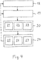
- Fig. 4 shows an embodiment in which first in an optional step (if just required), the focus setting of the camera is set (step: focusing 18), for example, the camera is focused on the outlet nozzle opening 6 or a protective glass 14.
- At least one image is taken with the camera 10 (process step: image acquisition 19).
- the image data are evaluated by an evaluation device 12, wherein at least one actual status feature of the laser processing head 4 is determined on the basis of the image data (method step: evaluation 20).
- the evaluation 20 in the evaluation device 12 can relate, for example, to the following actual status features: the determination 21 of the position of the laser beam (with respect to the outlet nozzle 5) and / or the determination 22 of features relating to the outlet nozzle 5 (eg presence, type, size of the outlet nozzle opening) 6, etc.) and / or the determination 23 of features relating to the protective glass 14 and / or an optical component 15 (eg presence, degree of contamination, etc.).
- control device 13 automatically sets at least one function of the determined actual status feature, in particular as a function of a deviation of the determined actual status feature from a desired status feature and / or as a function of exceeding a predetermined limit value by the determined actual status feature Action 24.
- the setting of an action 24 may be e.g. comprise: an adjustment 25 of the mirror 8 by driving the drive 9 and / or an output 26 of information regarding an actual status feature on an operator interface 16 and / or an interruption 27 of the laser processing operation.
- the actual status feature relates to the position of the laser beam 3 and the action set by the control unit 13 is that a mirror 8 arranged in the laser beam path 7 is moved onto the outlet nozzle 5 for deflecting the laser beam 3, whereby a predetermined , in particular centered, alignment of the laser beam 3 with respect to the outlet nozzle 5 is achieved.
- the image taken by the camera 10 comprises the contour of the outlet nozzle opening 6 and if, depending on a deviation of the actual position of the laser beam 3 from a desired position of the laser beam 3 with respect to the outlet nozzle opening 6, the drive 9 of the mirror 8 is controlled by the control device such that the laser beam 3 assumes the desired position (or this is constantly retraced).
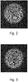
- FIGS. 2 and 3 show image recordings in which the large circle corresponds to the contour of the outlet nozzle opening 6 and the small circle corresponds to the contour of the process zone.
- the process zone is the area where the laser beam 3 meets the workpiece 2 and allows immediate Conclusion on the position of the laser beam 3.
- the jet is arranged decentrally to the nozzle and in Fig. 3 the laser beam 3 is correctly centered.
- the evaluation of the image data in an evaluation device 12 preferably includes an edge detection (using operators or filters), in particular to determine the contour of the outlet nozzle opening 6 and / or the contour of the laser beam 3.
- images are taken continuously with the camera 10 during a laser processing operation or at respective time intervals and that the position of the laser beam 3, if necessary, during the processing operation, preferably in real time, readjusted.
- the actual status feature relates to the presence or type of the outlet nozzle 5 or the size of the outlet nozzle opening 6, the type of outlet nozzle 5 preferably being determined on the basis of the size of the outlet nozzle opening 6. Mistacks can be avoided.
- the actual status feature may also relate to the presence or degree of soiling of an optical component 15 or protective glass 14 arranged behind the outlet nozzle 5, wherein preferably a spatial distribution of the contamination on the optical component 15 or protective glass 14 is determined. This can e.g. in that the degree of soiling in the central area and the degree of soiling in a peripheral area of the optical component 15 or protective glass 14 are determined and optionally related to each other.
- the action set by the control device 13 can output an information relating to the actual status feature to one Be interface 16 for the operator or an interruption of the machining process.
- an internal illumination 17 arranged within the laser processing head 4 can be switched on during the taking of an image by the camera 10 ( Fig. 1 ).
Claims (13)
- Dispositif d'usinage au laser (1) destiné à usiner une pièce d'oeuvre (2) avec un faisceau laser (3), notamment découpeuse au laser, comprenant une tête d'usinage (4) au laser avec une buse de sortie (5) du laser, une trajectoire du faisceau laser (7) définie à l'intérieur de la tête d'usinage (4) au laser, un miroir (8) placé dans la trajectoire du faisceau laser (7) et mobile, destiné à faire dévier le faisceau laser (3) sur la buse de sortie (5) et au moins une caméra (10) restituant des images, la trajectoire du faisceau (11) de la caméra étant orientée par l'intérieur sur la buse de sortie (5) et la caméra (10) étant reliée en communication avec un dispositif d'évaluation (12) de données d'images, le miroir (8) étant relié en communication avec un entraînement (9) destiné à déplacer le miroir (8), un système de commande (13) étant relié en communication avec l'entraînement (9) dudit miroir (8), le système de commande (13) étant conçu pour piloter automatiquement l'entraînement (9) du miroir (8), en fonction de l'évaluation réalisée par le dispositif d'évaluation (12) des données d'images enregistrées par la caméra (10), suite à quoi une orientation prédéfinie, notamment centrée du faisceau laser (3) latéralement au plan X-Y par rapport à la buse d'orientation (5) peut être obtenue, caractérisé en ce que le dispositif d'usinage au laser (1) comporte un unique miroir (8), le miroir (8) mobile étant un miroir sélectif de longueur d'ondes réfléchissant pour le faisceau laser (3) dans la trajectoire du faisceau laser (7) et transparent pour au moins une gamme d'ondes du spectre visible et en ce que la trajectoire du faisceau (11) de la caméra s'écoule à travers le miroir (8), de préférence la trajectoire du faisceau laser (7) et la trajectoire du faisceau (11) de la caméra se superposant dans la partie entre le miroir (8) et la buse de sortie (5).
- Dispositif d'usinage au laser selon la revendication 1, caractérisé en ce que la caméra (10) est placée au-dessus du miroir (8), de préférence en une ligne avec l'orifice (6) de la buse de sortie et le miroir (8).
- Dispositif d'usinage au laser selon l'une quelconque des revendications 1 ou 2, caractérisé en ce que l'entraînement (9) du miroir (8) est un entraînement dynamique, dont la dynamique est de préférence d'au moins 1 kHz, de manière particulièrement préférée d'au moins 2 kHz.
- Dispositif d'usinage au laser selon l'une quelconque des revendications 1 à 3, caractérisé en ce que la caméra (10) comprend un dispositif de focalisation, de préférence, avec la dispositif de focalisation, la caméra (10) pouvant être mise au point avec précision aussi bien sur la zone de la buse de sortie (5) qu'également sur la zone d'un verre protecteur (14) placé derrière la buse de sortie (5).
- Dispositif d'usinage au laser selon l'une quelconque des revendications 1 à 3, caractérisé en ce que le dispositif d'usinage au laser (1) comprend au moins deux caméras, une caméra pouvant être mise au point avec précision sur la zone de la buse de sortie (5) et l'autre caméra sur la zone d'un verre protecteur (14) placé derrière la buse de sortie (5), le cas échéant, un séparateur de faisceau étant placé dans au moins une trajectoire de faisceau de la caméra.
- Procédé d'usinage au laser, notamment procédé de découpage au laser, destiné à usiner une pièce d'oeuvre (2) avec un faisceau laser (3), avec un dispositif d'usinage au laser (1), notamment selon l'une quelconque des revendications précédentes, qui comprend une tête d'usinage (4) au laser avec une buse de sortie (5) du laser, une trajectoire du faisceau laser (7) définie à l'intérieur de la tête d'usinage (4) au laser et une caméra (10) qui délivre des images, caractérisé en ce que la trajectoire du faisceau (11) de la caméra est dévié à partir de l'intérieur sur la buse de sortie (5) par un unique miroir (8) sélectif de longueur d'ondes et placé dans la trajectoire du faisceau laser et mobile, à l'aide de la caméra (10), au moins une image étant enregistrée et évaluée avec un dispositif d'évaluation (12), à l'aide des données d'image, au moins la position du faisceau laser (3) en rapport à l'orifice (6) de la buse de sortie étant déterminée et en fonction d'un écart par rapport à une position de consigne, le miroir (8) étant automatiquement déplacé pour faire dévier le faisceau laser (3) sur la buse de sortie (5), suite à quoi une orientation prédéfinie, notamment centrée ou autre du faisceau laser (3) est obtenue latéralement au plan X-Y en rapport à la buse de sortie (5), l'image enregistrée par la caméra (10) englobant les contours de l'orifice (6) la buse de sortie et en ce qu'en fonction d'un écart entre une position réelle du faisceau laser (3) et la position de consigne du faisceau laser (3) en rapport à l'orifice (6) de la buse de sortie, l'entraînement (9) du miroir (8) est piloté par le système de commande, de telle sorte que le faisceau laser (3) adopte la position de consigne.
- Procédé d'usinage au laser selon la revendication 6, caractérisé en ce que l'évaluation des données d'images dans un dispositif d'évaluation (12) comprend une détection des arêtes, notamment pour déterminer le contour de l'orifice (6) de la buse de sortie et/ou le contour du faisceau laser (3).
- Procédé d'usinage au laser selon l'une quelconque des revendications 6 ou 7, caractérisé en ce qu'à l'aide de la caméra (10), pendant une opération d'usinage au laser, des enregistrements sont pris en continu ou chaque fois à des intervalles de temps et en ce que, si nécessaire pendant l'opération d'usinage, la position du faisceau laser (3) est réajustée, de préférence en temps réel.
- Procédé d'usinage au laser selon l'une quelconque des revendications 6 à 8, caractérisé en ce que la présence ou le type de la buse de sortie (5) ou la taille de l'orifice (6) de la buse de sortie est déterminé(e), de préférence à l'aide de la taille de l'orifice (6) de la buse de sortie ou à l'aide de la forme intérieure de la buse de sortie (5), le type de la buse de sortie (5) étant déterminé.
- Procédé d'usinage au laser selon l'une quelconque des revendications 6 à 9, caractérisé en ce que la présence ou le taux d'encrassement d'un composant optique (15) ou verre protecteur (14) placé derrière la buse de sortie (5) est déterminé(e), de préférence une distribution dans l'espace de l'encrassement sur le composant optique (15) ou verre protecteur (14) étant déterminée, par ex. le taux d'encrassement dans la zone centrale et le taux d'encrassement dans une zone périphérique du composant optique (15) ou verre protecteur (14).
- Procédé d'usinage au laser selon l'une quelconque des revendications 6 à 10, caractérisé en ce que par le système de commande (13), il s'effectue une édition d'une information concernant l'état déterminé sur une interface (16) à l'attention du personnel opérateur.
- Procédé d'usinage au laser selon l'une quelconque des revendications 6 à 11, caractérisé en ce qu'en fonction de l'état déterminé, le système de commande (13) provoque une interruption de l'opération d'usinage au laser.
- Procédé d'usinage au laser selon l'une quelconque des revendications 6 à 12, caractérisé en ce que pendant un enregistrement d'une image par la caméra (10), l'intérieur de la tête d'usinage (4) au laser est éclairé au moyen d'un éclairage intérieur (17).
Priority Applications (2)
| Application Number | Priority Date | Filing Date | Title |
|---|---|---|---|
| PL14150430T PL2894004T3 (pl) | 2014-01-08 | 2014-01-08 | Urządzenie do obróbki laserowej z kamerą i napędzanym zwierciadłem |
| EP14150430.8A EP2894004B1 (fr) | 2014-01-08 | 2014-01-08 | Dispositif de traitement laser avec une caméra et un mirroir mobile |
Applications Claiming Priority (1)
| Application Number | Priority Date | Filing Date | Title |
|---|---|---|---|
| EP14150430.8A EP2894004B1 (fr) | 2014-01-08 | 2014-01-08 | Dispositif de traitement laser avec une caméra et un mirroir mobile |
Publications (2)
| Publication Number | Publication Date |
|---|---|
| EP2894004A1 EP2894004A1 (fr) | 2015-07-15 |
| EP2894004B1 true EP2894004B1 (fr) | 2017-10-25 |
Family
ID=49916982
Family Applications (1)
| Application Number | Title | Priority Date | Filing Date |
|---|---|---|---|
| EP14150430.8A Active EP2894004B1 (fr) | 2014-01-08 | 2014-01-08 | Dispositif de traitement laser avec une caméra et un mirroir mobile |
Country Status (2)
| Country | Link |
|---|---|
| EP (1) | EP2894004B1 (fr) |
| PL (1) | PL2894004T3 (fr) |
Cited By (2)
| Publication number | Priority date | Publication date | Assignee | Title |
|---|---|---|---|---|
| EP3517241A1 (fr) | 2018-01-29 | 2019-07-31 | Bystronic Laser AG | Dispositif optique permettant de mettre en forme un faisceau d'ondes électromagnétiques et son utilisation, dispositif de traitement de faisceau et son utilisation et procédé de traitement de faisceau |
| EP3984687A1 (fr) | 2020-10-16 | 2022-04-20 | Bystronic Laser AG | Tête de traitement du faisceau et procédé de traitement du faisceau |
Families Citing this family (6)
| Publication number | Priority date | Publication date | Assignee | Title |
|---|---|---|---|---|
| DE102017213511A1 (de) * | 2017-08-03 | 2019-02-07 | Trumpf Werkzeugmaschinen Gmbh + Co. Kg | Verfahren zur Lasermaterialbearbeitung und Lasermaschine |
| JP6680751B2 (ja) | 2017-11-24 | 2020-04-15 | ファナック株式会社 | レーザ加工中に保護ウインドの汚れを警告するレーザ加工装置 |
| DE102018107666A1 (de) * | 2018-03-29 | 2019-10-02 | Alpha Laser Gmbh | Werkstückbearbeitung mittels Laserstrahlung |
| CN112705838A (zh) * | 2019-10-09 | 2021-04-27 | Nps株式会社 | 激光装置 |
| CN112692428A (zh) * | 2019-10-23 | 2021-04-23 | Nps株式会社 | 激光装置 |
| WO2022050436A1 (fr) * | 2020-09-03 | 2022-03-10 | 엘지전자 주식회사 | Appareil de traitement laser |
Citations (1)
| Publication number | Priority date | Publication date | Assignee | Title |
|---|---|---|---|---|
| US5449882A (en) * | 1993-03-15 | 1995-09-12 | Reliant Laser Corporation | Mirror-based laser-processing system with temperature and position control of moving laser spot |
Family Cites Families (10)
| Publication number | Priority date | Publication date | Assignee | Title |
|---|---|---|---|---|
| DE3339318C2 (de) | 1983-10-29 | 1995-05-24 | Trumpf Gmbh & Co | Laser-Bearbeitungsmaschine |
| DE3406677A1 (de) | 1984-02-24 | 1985-09-05 | Fa. Carl Zeiss, 7920 Heidenheim | Einrichtung zur kompensation der auswanderung eines laserstrahls |
| JPH04118193A (ja) * | 1990-09-04 | 1992-04-20 | Hitachi Constr Mach Co Ltd | レーザ加工装置の保護ガラス監視装置 |
| JP3761657B2 (ja) * | 1997-03-10 | 2006-03-29 | 株式会社アマダ | レーザ加工方法および装置 |
| EP1716963B1 (fr) | 2005-04-26 | 2008-10-22 | Highyag Lasertechnologie GmbH | Optiques pour le le travail à distance au laser permettant la création d'un espace de travail 3D |
| EP1728582A1 (fr) | 2005-05-31 | 2006-12-06 | Trumpf Laser- und Systemtechnik GmbH | Dispositif de détection des modifications d'un faisceau laser |
| DE102007013623A1 (de) * | 2007-03-21 | 2008-10-02 | Trumpf Werkzeugmaschinen Gmbh + Co. Kg | Verfahren und Vorrichtung zum Ausrichten eines Laserstrahls |
| DE102009007769B4 (de) | 2009-02-05 | 2016-07-14 | Jenoptik Automatisierungstechnik Gmbh | Laserbearbeitungskopf mit integrierter Sensoreinrichtung zur Fokuslagenüberwachung |
| WO2012000648A1 (fr) | 2010-06-28 | 2012-01-05 | Precitec Kg | Procédé de commande en boucle fermée d'une opération de traitement laser et tête de traitement de matériau au laser utilisant ce procédé |
| DE102011004117A1 (de) | 2011-02-15 | 2012-08-16 | Trumpf Laser- Und Systemtechnik Gmbh | Verfahren zur Kontrolle einer schneidenden Bearbeitung an einem Werkstück |
-
2014
- 2014-01-08 EP EP14150430.8A patent/EP2894004B1/fr active Active
- 2014-01-08 PL PL14150430T patent/PL2894004T3/pl unknown
Patent Citations (1)
| Publication number | Priority date | Publication date | Assignee | Title |
|---|---|---|---|---|
| US5449882A (en) * | 1993-03-15 | 1995-09-12 | Reliant Laser Corporation | Mirror-based laser-processing system with temperature and position control of moving laser spot |
Cited By (4)
| Publication number | Priority date | Publication date | Assignee | Title |
|---|---|---|---|---|
| EP3517241A1 (fr) | 2018-01-29 | 2019-07-31 | Bystronic Laser AG | Dispositif optique permettant de mettre en forme un faisceau d'ondes électromagnétiques et son utilisation, dispositif de traitement de faisceau et son utilisation et procédé de traitement de faisceau |
| WO2019145536A1 (fr) | 2018-01-29 | 2019-08-01 | Bystronic Laser Ag | Dispositif optique de mise en forme d'un faisceau d'ondes électromagnétiques et son utilisation, dispositif de traitement de faisceau et son utilisation, et procédé de traitement de faisceau |
| EP3984687A1 (fr) | 2020-10-16 | 2022-04-20 | Bystronic Laser AG | Tête de traitement du faisceau et procédé de traitement du faisceau |
| WO2022079239A1 (fr) | 2020-10-16 | 2022-04-21 | Bystronic Laser Ag | Tête d'usinage par faisceau et procédé d'usinage par faisceau |
Also Published As
| Publication number | Publication date |
|---|---|
| PL2894004T3 (pl) | 2018-04-30 |
| EP2894004A1 (fr) | 2015-07-15 |
Similar Documents
| Publication | Publication Date | Title |
|---|---|---|
| EP2894004B1 (fr) | Dispositif de traitement laser avec une caméra et un mirroir mobile | |
| EP1640101B1 (fr) | Méthode pour contrôler un procédé d'usinage automatique. | |
| EP2726244B1 (fr) | Procédé de détection de défauts sur une soudure non-linéaire ou une fente de coupe non-linéaire au cours d'un processus d'usinage par laser ; dispositif d'usinage par laser correspondant | |
| EP3838472B1 (fr) | Unité de déviation avec deux fenêtres, un élément optique et un dispositif de déviation | |
| EP2544849B1 (fr) | Tête de travail au laser et procédé de travail au laser | |
| DE102015012565B3 (de) | Vorrichtung und Verfahren zur Erhöhung der Genauigkeit eines OCT-Messsystems für die Lasermaterialbearbeitung | |
| EP3294488B1 (fr) | Dispositif de decoupe laser avec un systeme d'observation | |
| DE102013015656B4 (de) | Verfahren zum Messen der Eindringtiefe eines Laserstrahls in ein Werkstück, Verfahren zum Bearbeiten eines Werkstücks sowie Laserbearbeitungsvorrichtung | |
| DE4336136C2 (de) | Laserbearbeitungsvorrichtung und -verfahren | |
| DE102014000330B3 (de) | Verfahren zur Überwachung und Regelung der Fokuslage eines Bearbeitungslaserstrahls beim Laserschneiden | |
| DE10297255B4 (de) | Verfahren und Vorrichtung zum Überwachen und Einstellen eines Laserschweißprozesses | |
| DE102013209526B4 (de) | Verfahren, Computerprogrammprodukt und Vorrichtung zum Erkennen eines Schnittabrisses | |
| EP3159093A1 (fr) | Methode de controle d'un procede de decoupe au laser de haute energie avec interruption du procede de decoupage ; dispositif et programme d'ordinateur correspondants | |
| DE102013226961B4 (de) | Prüfvorrichtung und Verfahren zur rechnergestützten Überwachung eines an einer Bearbeitungsoptik angebrachten Werkzeugteils einer Vorrichtung zur Materialbearbeitung sowie Vorrichtung zur rechnergestützten Materialbearbeitung | |
| EP3102361B1 (fr) | Procédé pour identifier le contour de bord d'une ouverture formée sur une tête d'usinage et machine d'usinage associée | |
| EP3313607B1 (fr) | Tête de traitement par laser et machine avec une telle tête | |
| DE102020000630B4 (de) | Verfahren und Vorrichtung zum Durchführen und Überwachen eines Bearbeitungsprozesses eines Werkstücks | |
| WO2020104100A1 (fr) | Procédé pour couper une pièce au moyen d'un faisceau laser et système d'usinage laser utilisé pour mettre ce procédé en œuvre | |
| WO2021140037A1 (fr) | Procédé pour positionner automatiquement un faisceau laser par rapport à une buse d'une tête d'usinage au laser, et système d'usinage au laser pour usiner une pièce au moyen d'un faisceau laser | |
| DE102020110087A1 (de) | Verfahren zur prozesskontrolle bei der lasermaterialbearbeitung | |
| DE102017009559B4 (de) | Messvorrichtung zum Überwachen, System zum Bearbeiten und Überwachen sowie Verfahren zum Überwachen | |
| DE102020211533B3 (de) | Messinstrument für ein Laserwerkzeug, Laserwerkzeug und Werkstückbearbeitungsvorrichtung sowie Verfahren zum Messen eines Abstands | |
| WO2023135226A2 (fr) | Module de surveillance de processus pour surveiller un processus d'usinage laser et système d'usinage laser le comprenant | |
| DE102022106605A1 (de) | Laserbearbeitungsverfahren und Laserbearbeitungsmaschine |
Legal Events
| Date | Code | Title | Description |
|---|---|---|---|
| PUAI | Public reference made under article 153(3) epc to a published international application that has entered the european phase |
Free format text: ORIGINAL CODE: 0009012 |
|
| 17P | Request for examination filed |
Effective date: 20140108 |
|
| AK | Designated contracting states |
Kind code of ref document: A1 Designated state(s): AL AT BE BG CH CY CZ DE DK EE ES FI FR GB GR HR HU IE IS IT LI LT LU LV MC MK MT NL NO PL PT RO RS SE SI SK SM TR |
|
| AX | Request for extension of the european patent |
Extension state: BA ME |
|
| R17P | Request for examination filed (corrected) |
Effective date: 20160115 |
|
| RBV | Designated contracting states (corrected) |
Designated state(s): AL AT BE BG CH CY CZ DE DK EE ES FI FR GB GR HR HU IE IS IT LI LT LU LV MC MK MT NL NO PL PT RO RS SE SI SK SM TR |
|
| 17Q | First examination report despatched |
Effective date: 20160708 |
|
| STAA | Information on the status of an ep patent application or granted ep patent |
Free format text: STATUS: EXAMINATION IS IN PROGRESS |
|
| GRAP | Despatch of communication of intention to grant a patent |
Free format text: ORIGINAL CODE: EPIDOSNIGR1 |
|
| STAA | Information on the status of an ep patent application or granted ep patent |
Free format text: STATUS: GRANT OF PATENT IS INTENDED |
|
| INTG | Intention to grant announced |
Effective date: 20170412 |
|
| GRAJ | Information related to disapproval of communication of intention to grant by the applicant or resumption of examination proceedings by the epo deleted |
Free format text: ORIGINAL CODE: EPIDOSDIGR1 |
|
| STAA | Information on the status of an ep patent application or granted ep patent |
Free format text: STATUS: EXAMINATION IS IN PROGRESS |
|
| GRAP | Despatch of communication of intention to grant a patent |
Free format text: ORIGINAL CODE: EPIDOSNIGR1 |
|
| STAA | Information on the status of an ep patent application or granted ep patent |
Free format text: STATUS: GRANT OF PATENT IS INTENDED |
|
| INTC | Intention to grant announced (deleted) | ||
| INTG | Intention to grant announced |
Effective date: 20170810 |
|
| GRAS | Grant fee paid |
Free format text: ORIGINAL CODE: EPIDOSNIGR3 |
|
| GRAA | (expected) grant |
Free format text: ORIGINAL CODE: 0009210 |
|
| STAA | Information on the status of an ep patent application or granted ep patent |
Free format text: STATUS: THE PATENT HAS BEEN GRANTED |
|
| AK | Designated contracting states |
Kind code of ref document: B1 Designated state(s): AL AT BE BG CH CY CZ DE DK EE ES FI FR GB GR HR HU IE IS IT LI LT LU LV MC MK MT NL NO PL PT RO RS SE SI SK SM TR |
|
| REG | Reference to a national code |
Ref country code: GB Ref legal event code: FG4D Free format text: NOT ENGLISH |
|
| REG | Reference to a national code |
Ref country code: CH Ref legal event code: EP |
|
| REG | Reference to a national code |
Ref country code: AT Ref legal event code: REF Ref document number: 939468 Country of ref document: AT Kind code of ref document: T Effective date: 20171115 |
|
| REG | Reference to a national code |
Ref country code: IE Ref legal event code: FG4D Free format text: LANGUAGE OF EP DOCUMENT: GERMAN |
|
| REG | Reference to a national code |
Ref country code: DE Ref legal event code: R096 Ref document number: 502014005926 Country of ref document: DE |
|
| REG | Reference to a national code |
Ref country code: FR Ref legal event code: PLFP Year of fee payment: 5 |
|
| REG | Reference to a national code |
Ref country code: NL Ref legal event code: MP Effective date: 20171025 |
|
| REG | Reference to a national code |
Ref country code: LT Ref legal event code: MG4D |
|
| PG25 | Lapsed in a contracting state [announced via postgrant information from national office to epo] |
Ref country code: NL Free format text: LAPSE BECAUSE OF FAILURE TO SUBMIT A TRANSLATION OF THE DESCRIPTION OR TO PAY THE FEE WITHIN THE PRESCRIBED TIME-LIMIT Effective date: 20171025 |
|
| PG25 | Lapsed in a contracting state [announced via postgrant information from national office to epo] |
Ref country code: ES Free format text: LAPSE BECAUSE OF FAILURE TO SUBMIT A TRANSLATION OF THE DESCRIPTION OR TO PAY THE FEE WITHIN THE PRESCRIBED TIME-LIMIT Effective date: 20171025 Ref country code: FI Free format text: LAPSE BECAUSE OF FAILURE TO SUBMIT A TRANSLATION OF THE DESCRIPTION OR TO PAY THE FEE WITHIN THE PRESCRIBED TIME-LIMIT Effective date: 20171025 Ref country code: NO Free format text: LAPSE BECAUSE OF FAILURE TO SUBMIT A TRANSLATION OF THE DESCRIPTION OR TO PAY THE FEE WITHIN THE PRESCRIBED TIME-LIMIT Effective date: 20180125 Ref country code: LT Free format text: LAPSE BECAUSE OF FAILURE TO SUBMIT A TRANSLATION OF THE DESCRIPTION OR TO PAY THE FEE WITHIN THE PRESCRIBED TIME-LIMIT Effective date: 20171025 Ref country code: SE Free format text: LAPSE BECAUSE OF FAILURE TO SUBMIT A TRANSLATION OF THE DESCRIPTION OR TO PAY THE FEE WITHIN THE PRESCRIBED TIME-LIMIT Effective date: 20171025 |
|
| PG25 | Lapsed in a contracting state [announced via postgrant information from national office to epo] |
Ref country code: GR Free format text: LAPSE BECAUSE OF FAILURE TO SUBMIT A TRANSLATION OF THE DESCRIPTION OR TO PAY THE FEE WITHIN THE PRESCRIBED TIME-LIMIT Effective date: 20180126 Ref country code: LV Free format text: LAPSE BECAUSE OF FAILURE TO SUBMIT A TRANSLATION OF THE DESCRIPTION OR TO PAY THE FEE WITHIN THE PRESCRIBED TIME-LIMIT Effective date: 20171025 Ref country code: HR Free format text: LAPSE BECAUSE OF FAILURE TO SUBMIT A TRANSLATION OF THE DESCRIPTION OR TO PAY THE FEE WITHIN THE PRESCRIBED TIME-LIMIT Effective date: 20171025 Ref country code: IS Free format text: LAPSE BECAUSE OF FAILURE TO SUBMIT A TRANSLATION OF THE DESCRIPTION OR TO PAY THE FEE WITHIN THE PRESCRIBED TIME-LIMIT Effective date: 20180225 Ref country code: BG Free format text: LAPSE BECAUSE OF FAILURE TO SUBMIT A TRANSLATION OF THE DESCRIPTION OR TO PAY THE FEE WITHIN THE PRESCRIBED TIME-LIMIT Effective date: 20180125 Ref country code: RS Free format text: LAPSE BECAUSE OF FAILURE TO SUBMIT A TRANSLATION OF THE DESCRIPTION OR TO PAY THE FEE WITHIN THE PRESCRIBED TIME-LIMIT Effective date: 20171025 |
|
| REG | Reference to a national code |
Ref country code: DE Ref legal event code: R097 Ref document number: 502014005926 Country of ref document: DE |
|
| PG25 | Lapsed in a contracting state [announced via postgrant information from national office to epo] |
Ref country code: CZ Free format text: LAPSE BECAUSE OF FAILURE TO SUBMIT A TRANSLATION OF THE DESCRIPTION OR TO PAY THE FEE WITHIN THE PRESCRIBED TIME-LIMIT Effective date: 20171025 Ref country code: SK Free format text: LAPSE BECAUSE OF FAILURE TO SUBMIT A TRANSLATION OF THE DESCRIPTION OR TO PAY THE FEE WITHIN THE PRESCRIBED TIME-LIMIT Effective date: 20171025 Ref country code: DK Free format text: LAPSE BECAUSE OF FAILURE TO SUBMIT A TRANSLATION OF THE DESCRIPTION OR TO PAY THE FEE WITHIN THE PRESCRIBED TIME-LIMIT Effective date: 20171025 Ref country code: CY Free format text: LAPSE BECAUSE OF FAILURE TO SUBMIT A TRANSLATION OF THE DESCRIPTION OR TO PAY THE FEE WITHIN THE PRESCRIBED TIME-LIMIT Effective date: 20171025 Ref country code: EE Free format text: LAPSE BECAUSE OF FAILURE TO SUBMIT A TRANSLATION OF THE DESCRIPTION OR TO PAY THE FEE WITHIN THE PRESCRIBED TIME-LIMIT Effective date: 20171025 |
|
| PG25 | Lapsed in a contracting state [announced via postgrant information from national office to epo] |
Ref country code: RO Free format text: LAPSE BECAUSE OF FAILURE TO SUBMIT A TRANSLATION OF THE DESCRIPTION OR TO PAY THE FEE WITHIN THE PRESCRIBED TIME-LIMIT Effective date: 20171025 Ref country code: SM Free format text: LAPSE BECAUSE OF FAILURE TO SUBMIT A TRANSLATION OF THE DESCRIPTION OR TO PAY THE FEE WITHIN THE PRESCRIBED TIME-LIMIT Effective date: 20171025 |
|
| PLBE | No opposition filed within time limit |
Free format text: ORIGINAL CODE: 0009261 |
|
| STAA | Information on the status of an ep patent application or granted ep patent |
Free format text: STATUS: NO OPPOSITION FILED WITHIN TIME LIMIT |
|
| PG25 | Lapsed in a contracting state [announced via postgrant information from national office to epo] |
Ref country code: MT Free format text: LAPSE BECAUSE OF FAILURE TO SUBMIT A TRANSLATION OF THE DESCRIPTION OR TO PAY THE FEE WITHIN THE PRESCRIBED TIME-LIMIT Effective date: 20171025 |
|
| 26N | No opposition filed |
Effective date: 20180726 |
|
| PG25 | Lapsed in a contracting state [announced via postgrant information from national office to epo] |
Ref country code: LU Free format text: LAPSE BECAUSE OF NON-PAYMENT OF DUE FEES Effective date: 20180108 |
|
| REG | Reference to a national code |
Ref country code: IE Ref legal event code: MM4A |
|
| PG25 | Lapsed in a contracting state [announced via postgrant information from national office to epo] |
Ref country code: SI Free format text: LAPSE BECAUSE OF FAILURE TO SUBMIT A TRANSLATION OF THE DESCRIPTION OR TO PAY THE FEE WITHIN THE PRESCRIBED TIME-LIMIT Effective date: 20171025 |
|
| PG25 | Lapsed in a contracting state [announced via postgrant information from national office to epo] |
Ref country code: IE Free format text: LAPSE BECAUSE OF NON-PAYMENT OF DUE FEES Effective date: 20180108 |
|
| PG25 | Lapsed in a contracting state [announced via postgrant information from national office to epo] |
Ref country code: MC Free format text: LAPSE BECAUSE OF FAILURE TO SUBMIT A TRANSLATION OF THE DESCRIPTION OR TO PAY THE FEE WITHIN THE PRESCRIBED TIME-LIMIT Effective date: 20171025 |
|
| REG | Reference to a national code |
Ref country code: AT Ref legal event code: MM01 Ref document number: 939468 Country of ref document: AT Kind code of ref document: T Effective date: 20190108 |
|
| PG25 | Lapsed in a contracting state [announced via postgrant information from national office to epo] |
Ref country code: AT Free format text: LAPSE BECAUSE OF NON-PAYMENT OF DUE FEES Effective date: 20190108 |
|
| PG25 | Lapsed in a contracting state [announced via postgrant information from national office to epo] |
Ref country code: PT Free format text: LAPSE BECAUSE OF FAILURE TO SUBMIT A TRANSLATION OF THE DESCRIPTION OR TO PAY THE FEE WITHIN THE PRESCRIBED TIME-LIMIT Effective date: 20171025 |
|
| PG25 | Lapsed in a contracting state [announced via postgrant information from national office to epo] |
Ref country code: MK Free format text: LAPSE BECAUSE OF NON-PAYMENT OF DUE FEES Effective date: 20171025 Ref country code: HU Free format text: LAPSE BECAUSE OF FAILURE TO SUBMIT A TRANSLATION OF THE DESCRIPTION OR TO PAY THE FEE WITHIN THE PRESCRIBED TIME-LIMIT; INVALID AB INITIO Effective date: 20140108 |
|
| PG25 | Lapsed in a contracting state [announced via postgrant information from national office to epo] |
Ref country code: AL Free format text: LAPSE BECAUSE OF FAILURE TO SUBMIT A TRANSLATION OF THE DESCRIPTION OR TO PAY THE FEE WITHIN THE PRESCRIBED TIME-LIMIT Effective date: 20171025 |
|
| PGFP | Annual fee paid to national office [announced via postgrant information from national office to epo] |
Ref country code: PL Payment date: 20221203 Year of fee payment: 10 Ref country code: BE Payment date: 20221216 Year of fee payment: 10 |
|
| PGFP | Annual fee paid to national office [announced via postgrant information from national office to epo] |
Ref country code: CH Payment date: 20230106 Year of fee payment: 10 |
|
| PGFP | Annual fee paid to national office [announced via postgrant information from national office to epo] |
Ref country code: TR Payment date: 20230106 Year of fee payment: 10 Ref country code: IT Payment date: 20221213 Year of fee payment: 10 Ref country code: DE Payment date: 20221207 Year of fee payment: 10 |
|
| P01 | Opt-out of the competence of the unified patent court (upc) registered |
Effective date: 20230522 |
|
| PGFP | Annual fee paid to national office [announced via postgrant information from national office to epo] |
Ref country code: GB Payment date: 20231207 Year of fee payment: 11 |
|
| PGFP | Annual fee paid to national office [announced via postgrant information from national office to epo] |
Ref country code: FR Payment date: 20231222 Year of fee payment: 11 |
|
| PGFP | Annual fee paid to national office [announced via postgrant information from national office to epo] |
Ref country code: BE Payment date: 20231219 Year of fee payment: 11 |