EP2894004B1 - Device for laser machining with a camera and a movavble mirror - Google Patents
Device for laser machining with a camera and a movavble mirror Download PDFInfo
- Publication number
- EP2894004B1 EP2894004B1 EP14150430.8A EP14150430A EP2894004B1 EP 2894004 B1 EP2894004 B1 EP 2894004B1 EP 14150430 A EP14150430 A EP 14150430A EP 2894004 B1 EP2894004 B1 EP 2894004B1
- Authority
- EP
- European Patent Office
- Prior art keywords
- laser
- camera
- mirror
- laser beam
- laser machining
- Prior art date
- Legal status (The legal status is an assumption and is not a legal conclusion. Google has not performed a legal analysis and makes no representation as to the accuracy of the status listed.)
- Active
Links
- 238000003754 machining Methods 0.000 title claims description 32
- 238000000034 method Methods 0.000 claims description 25
- 238000011156 evaluation Methods 0.000 claims description 22
- 230000001681 protective effect Effects 0.000 claims description 22
- 239000011521 glass Substances 0.000 claims description 21
- 230000003287 optical effect Effects 0.000 claims description 15
- 238000011109 contamination Methods 0.000 claims description 11
- 238000003384 imaging method Methods 0.000 claims description 8
- 238000003698 laser cutting Methods 0.000 claims description 7
- 238000011157 data evaluation Methods 0.000 claims description 4
- 238000009826 distribution Methods 0.000 claims description 3
- 238000003708 edge detection Methods 0.000 claims description 3
- 230000002093 peripheral effect Effects 0.000 claims description 3
- 238000001429 visible spectrum Methods 0.000 claims description 3
- 238000004891 communication Methods 0.000 claims 3
- 230000000694 effects Effects 0.000 claims 1
- 239000005336 safety glass Substances 0.000 claims 1
- 238000012545 processing Methods 0.000 description 57
- 238000012544 monitoring process Methods 0.000 description 6
- 238000005520 cutting process Methods 0.000 description 4
- 230000001419 dependent effect Effects 0.000 description 3
- 238000001514 detection method Methods 0.000 description 3
- 238000003672 processing method Methods 0.000 description 3
- 230000003044 adaptive effect Effects 0.000 description 2
- 239000000853 adhesive Substances 0.000 description 1
- 230000001070 adhesive effect Effects 0.000 description 1
- 238000013461 design Methods 0.000 description 1
- 238000011161 development Methods 0.000 description 1
- 230000018109 developmental process Effects 0.000 description 1
- 238000005286 illumination Methods 0.000 description 1
- 239000000463 material Substances 0.000 description 1
- 230000000149 penetrating effect Effects 0.000 description 1
- 230000005855 radiation Effects 0.000 description 1
- 230000003595 spectral effect Effects 0.000 description 1
- 238000012360 testing method Methods 0.000 description 1
- 238000011144 upstream manufacturing Methods 0.000 description 1
- 230000000007 visual effect Effects 0.000 description 1
Images

Classifications
-
- B—PERFORMING OPERATIONS; TRANSPORTING
- B23—MACHINE TOOLS; METAL-WORKING NOT OTHERWISE PROVIDED FOR
- B23K—SOLDERING OR UNSOLDERING; WELDING; CLADDING OR PLATING BY SOLDERING OR WELDING; CUTTING BY APPLYING HEAT LOCALLY, e.g. FLAME CUTTING; WORKING BY LASER BEAM
- B23K26/00—Working by laser beam, e.g. welding, cutting or boring
- B23K26/02—Positioning or observing the workpiece, e.g. with respect to the point of impact; Aligning, aiming or focusing the laser beam
- B23K26/03—Observing, e.g. monitoring, the workpiece
-
- B—PERFORMING OPERATIONS; TRANSPORTING
- B23—MACHINE TOOLS; METAL-WORKING NOT OTHERWISE PROVIDED FOR
- B23K—SOLDERING OR UNSOLDERING; WELDING; CLADDING OR PLATING BY SOLDERING OR WELDING; CUTTING BY APPLYING HEAT LOCALLY, e.g. FLAME CUTTING; WORKING BY LASER BEAM
- B23K26/00—Working by laser beam, e.g. welding, cutting or boring
- B23K26/02—Positioning or observing the workpiece, e.g. with respect to the point of impact; Aligning, aiming or focusing the laser beam
- B23K26/04—Automatically aligning, aiming or focusing the laser beam, e.g. using the back-scattered light
- B23K26/042—Automatically aligning the laser beam
- B23K26/043—Automatically aligning the laser beam along the beam path, i.e. alignment of laser beam axis relative to laser beam apparatus
-
- B—PERFORMING OPERATIONS; TRANSPORTING
- B23—MACHINE TOOLS; METAL-WORKING NOT OTHERWISE PROVIDED FOR
- B23K—SOLDERING OR UNSOLDERING; WELDING; CLADDING OR PLATING BY SOLDERING OR WELDING; CUTTING BY APPLYING HEAT LOCALLY, e.g. FLAME CUTTING; WORKING BY LASER BEAM
- B23K26/00—Working by laser beam, e.g. welding, cutting or boring
- B23K26/14—Working by laser beam, e.g. welding, cutting or boring using a fluid stream, e.g. a jet of gas, in conjunction with the laser beam; Nozzles therefor
- B23K26/1462—Nozzles; Features related to nozzles
-
- B—PERFORMING OPERATIONS; TRANSPORTING
- B23—MACHINE TOOLS; METAL-WORKING NOT OTHERWISE PROVIDED FOR
- B23K—SOLDERING OR UNSOLDERING; WELDING; CLADDING OR PLATING BY SOLDERING OR WELDING; CUTTING BY APPLYING HEAT LOCALLY, e.g. FLAME CUTTING; WORKING BY LASER BEAM
- B23K26/00—Working by laser beam, e.g. welding, cutting or boring
- B23K26/36—Removing material
- B23K26/38—Removing material by boring or cutting
Definitions
- the invention relates to a laser processing apparatus according to the preamble of claim 1 and to a laser processing method according to the preamble of claim 6 (see, for example, US Pat. JP H10 249 566 A ).
- the JP H04 118193 A discloses the detection of the degree of soiling of the protective glass by means of an image sensor or a camera. This camera is positioned above a stationary, rigid deflection mirror for the working laser beam and in line with this mirror and the exit nozzle.
- the JP H10 249566 A discloses an arrangement of two deflection mirrors for the working laser beam, which both mirrors must be moved under the control of a control device in order to adjust the working laser beam with respect to the exit nozzle.
- the position of the laser beam is determined via a camera within the machining head and the adjustment is effected by means of movement of both mirrors.
- the camera is positioned between the last deflection mirror and an optical element above the outlet nozzle.
- the EP1728582A1 discloses a device for detecting changes in the laser beam.
- a sensor for detecting laser beam changes is arranged in front of the laser processing head.
- a controller evaluates the data from the sensor and drives an adaptive mirror. With the in-process determined data, the adaptive mirror 2, according to predetermined data, adjusted.
- the control unit can record the measured values of the laser beam and compare them with nominal values. With such a system, a change in the diameter of the laser beam between the output mirror of the laser and the processing head of the laser processing machine can be compensated.
- the US5449882 discloses a laser processing system in which a beam splitter is adjustable by means of piezoelectric drive.
- a microscope head can be focused on the object to be processed to position the initial position of the laser spot on the object.
- the control of the piezoelectric drive is performed by the operator by means of a joystick.
- the EP0147525B1 discloses a laser processing apparatus in which an automatic adjustment of deflecting mirrors takes place as a function of the deviation of the beam position from a desired value.
- a test device is provided which is located immediately above the outlet nozzle.
- This type of detector is on the one hand able to detect a laser beam, even if it belongs to the non-visible area, without taking self-damage by the laser beam and the deviation of the actual value of a target value, ie the desired normal position of the laser beam, in a suitable display and / or adjustment value for an adjustment of the one or more controllable mirror converts.
- the EP0154866B1 discloses a laser processing machine in which the offset or angle changes of the laser beam is corrected via controllable adjusting mirrors. To detect the offset or angle changes position-sensitive, photoelectric detectors are mentioned. In this case, a portion of the laser light is reflected in the direction of the detector or a pilot laser used.
- the WO2012000648A1 discloses a 'closed loop' controller for a laser processing operation using a camera.
- the EP1716963B1 discloses a laser material processing with a pivotable mirror which deflects the laser beam.
- the DE102011004117A1 discloses a laser processing machine with a partially transmissive mirror behind which a beam path is guided in the direction of a camera.
- the camera and the evaluation device connected thereto are used for process monitoring, in particular detection of a tilt angle of a workpiece part or faulty machining.
- the EP2216129A1 discloses a system for focus position monitoring. In this case, a lens is driven. It is also known to position the laser beam via a manual beam adjustment. The actual position of the laser beam is assessed today on the basis of the position of a laser bullet hole on a temporarily attached adhesive strip on the outlet nozzle.
- the disadvantages resulting from the prior art are that a reliable imaging of the laser beam impinging on the workpiece, in particular in relation to the outlet nozzle, is not possible. In other systems, it is left to the operator to position the laser beam by hand.
- the prior art solutions using a detector are complex in structure and susceptible to contamination.
- a disadvantage of many of these solutions is also that a detection of the laser beam is outside the laser processing head, so that lateral position shifts of the laser spot on the workpiece are not registered at all.
- the object of the present invention is thus to eliminate these disadvantages and to provide a laser processing apparatus with which a reliable imaging of the outlet nozzle or of the outlet nozzle upstream of transparent components can be achieved.
- an automation of the laser machining process is to be ensured, which leads to an optimal workpiece machining. It is to be prevented that errors or inadmissible operating states, which are assigned to the area of the laser processing head, lead to a qualitatively inferior processing.
- a laser processing apparatus for processing a workpiece with a laser beam, in particular a laser cutting machine, comprising a laser processing head with a laser exit nozzle, a defined within the laser processing head laser beam path, a single arranged in the laser beam path and movable mirror for deflecting the laser beam to the outlet nozzle, and at least one imaging camera, wherein the camera beam path directed from the inside to the outlet nozzle and the camera is communicatively connected to an image data evaluation device.
- the mirror is movable and communicatively connected to a drive for moving the mirror, whereby a control device is also communicatively connected to the drive of the one mirror, wherein the control device is designed to drive the drive as a function of the evaluation of the image data recorded by the camera the mirror to be automatically controlled, whereby a predetermined, in particular centered, alignment of the laser beam laterally in the XY plane with respect to the outlet nozzle is achievable.
- the mirror is a wavelength-selective mirror, which is reflective for the laser beam in the laser beam path and permeable to at least one wavelength range of the visible spectrum, and that the camera beam path passes through the mirror, wherein preferably the laser beam path and the camera Overlay the beam path in the section between the mirror and the outlet nozzle.
- the advantage of the invention is that the actual position of the laser beam on the workpiece can be determined exactly by an image acquisition.
- the control device can be used to correct the jet position by pivoting the mirror, which results in automatic regulation.
- This arrangement also allows the decoupling of the laser beam from that received by the camera (visible) light.
- the images are not affected by the laser beam fed into the laser processing head, resulting in high-quality images that are accessible for reliable evaluation.
- the laser processing head e.g. Cutting head
- the laser processing head is preferably equipped with a motor-operated, dynamic pivoting mirror. This allows the laser beam to be adjusted laterally in the X / Y plane, relative to the exit nozzle.
- the camera is preferably arranged inside the laser processing head. In combination with the camera, an automatic beam adjustment, in particular beam centering, can be realized relative to the outlet nozzle opening. By pivoting or moving the mirror through the mirror drive controlled by the control device, the laser beam can be exactly aligned relative to the outlet nozzle.
- the evaluation device and the control device are also communicatively connected with each other or form a structural unit anyway.
- the mirror is preferably transmissive in the visual spectral region (preferred exception: wavelength for a pilot laser is reflected) and the camera is behind the mirror.
- the lateral beam position is checked with the camera and readjusted if necessary. This allows online control of the jet position to the outlet nozzle.
- a loss of the nozzle can also be controlled. There is also the possibility - especially in combination with an interior lighting - to determine the outlet nozzle type (various geometric shapes).
- a focusable camera system it is also possible to monitor the protective glass or optical components in the camera beam path. It is possible to detect the presence and the degree of pollution.
- Known systems determine the degree of contamination on the basis of the scattered radiation, based on the can not be determined whether a pollution is present in the middle (critical) or rather on the edge (non-critical).
- a camera system can determine the size and location of the contamination and deduce whether this is critical or uncritical for the laser processing operation.
- the lateral beam position is checked and readjusted during or before piercing and / or cutting with the camera. This allows online control of the jet position to the nozzle.
- the camera is designed to receive visible light and is preferably arranged above the outlet nozzle opening and behind the mirror.
- a preferred embodiment is characterized in that the camera is arranged above the mirror, preferably in a line with the outlet nozzle opening and the mirror. Here is the mirror between the outlet nozzle and the camera. The camera beam path is thus not deflected, resulting in a compact design.
- the camera is arranged within the laser processing head, ie the camera beam path does not have to be led out of the head.
- the mirror and drive is located within the laser processing head.
- the laser processing head thus represents a compact module with far more integrated functionality than is the case with known systems.
- a preferred embodiment is characterized in that the drive of the mirror is a dynamic drive whose dynamics is preferably at least 1 kHz, more preferably at least 2 kHz. This allows for real-time tracking of the laser beam, allowing for high quality cuts.
- the drive is preferably a piezoelectric drive.
- a preferred embodiment is characterized in that the camera comprises a focusing device, wherein preferably the camera with the focusing device is sharply adjustable both on the region of the outlet nozzle and on the region of a protective glass arranged behind the outlet nozzle.
- the laser processing device comprises at least two cameras, wherein one camera is focused on the region of the outlet nozzle and the other camera on the region of a protective glass arranged behind the outlet nozzle.
- a beam splitter can be arranged in at least one camera beam path or in the beam paths of the two cameras.
- a laser processing method for processing a workpiece with a laser beam.
- a laser processing device (in particular according to one of the preceding embodiments) comprising a laser processing head with a laser exit nozzle, a laser beam path defined within the laser processing head and an imaging camera, the camera beam path directed from the inside onto the exit nozzle is.
- At least one image is taken with the camera and evaluated with an evaluation device, wherein at least the position of the laser beam with respect to the outlet nozzle opening is determined on the basis of the image data.
- a single arranged in the laser beam path and movable mirror for deflecting the laser beam is automatically moved to the outlet nozzle , whereby a predetermined, in particular centered or otherwise, alignment of the laser beam is achieved laterally in the XY plane with respect to the outlet nozzle.
- the image taken by the camera comprises the contour of the outlet nozzle opening, and in dependence on a deviation of the actual position of the laser beam from a desired position of the laser beam with respect to the outlet nozzle opening, the drive of the mirror is controlled by the control device such that the laser beam assumes the target position.
- this enables automatic monitoring which, in the case of an undesired state, an error, a positional deviation, leads to an action of the control device, ie an automatic reaction of the system takes place.
- the exit nozzle opening represents a reliable reference contained in the same image as the laser beam (spot) impinging on the workpiece. Position determination thus meets the highest requirements.
- the desired position is preferably a centered position with respect to the outlet nozzle opening.
- a preferred embodiment is characterized in that the evaluation of the image data in an evaluation device comprises an edge detection, in particular in order to determine the contour of the outlet nozzle opening and / or the contour of the laser beam. The position determination can be done very accurately.
- a preferred embodiment is characterized in that with the camera during a laser processing operation continuously or in each case in time intervals taken pictures and that the position of the laser beam, if necessary, during the processing operation, preferably in real time, readjusted. Process-related (for example, sometimes dependent) deviations can be compensated for immediately.
- a preferred embodiment is characterized in that the presence or the type of outlet nozzle or the size of the outlet nozzle opening is determined, wherein the type of outlet nozzle is preferably determined on the basis of the size of the outlet nozzle opening or on the basis of the inner shape of the outlet nozzle. Operation without a nozzle or with a wrong nozzle is thus prevented from the outset.
- a preferred embodiment is characterized in that the presence or the degree of contamination of an optical component or protective glass arranged behind the outlet nozzle is determined, wherein preferably a spatial distribution of the contamination on the optical component or protective glass is determined, e.g. the degree of soiling in the central area and the degree of soiling in a peripheral area of the optical component or protective glass. This also allows other components to be detected reliably and monitored in their condition.
- a preferred embodiment is characterized in that the control device outputs information relating to the determined status to an interface for the operating personnel (for example, screen, audible indicator, flashing light, etc.).
- the operating personnel can be informed immediately if an error or inadmissible condition occurs.
- a preferred embodiment is characterized in that the control device causes an interruption of the laser processing operation in dependence on the determined status.
- a preferred embodiment is characterized in that during a recording of an image by the camera, the interior of the laser processing head is illuminated by means of an interior lighting. This can further increase the picture quality.
- Fig. 1 shows a laser processing apparatus 1 for processing a workpiece 2 with a laser beam 3 in the form of a laser cutting machine.
- the laser processing apparatus 1 comprises a laser processing head 4 with a laser exit nozzle 5, a laser beam path 7 defined within the laser processing head 4, a mirror 8 arranged in the laser beam path 7 for deflecting the laser beam 3 onto the exit nozzle 5, a drive 9 for moving the laser Mirror 8 and an imaging camera 10, wherein the camera beam path 11 is directed from the inside to the outlet nozzle 5.
- the laser beam path 7 is further an optical component 15, for example a converging lens, and a protective glass 14 are arranged before the laser beam passes through the outlet nozzle opening 6 from the laser processing head.
- the protective glass 14 prevents dirt and moisture from penetrating into the laser processing head 4.
- the camera 10 is communicatively connected to an image data evaluation device 12 and the drive 9 of the mirror 8 is connected to a control device 13, wherein the control device 13 is designed to control the drive 9 as a function of the evaluation of the image data recorded by the camera 10, carried out by the evaluation device 12 of the mirror 8 to control automatically, whereby a predetermined, in particular centered, alignment of the laser beam 3 in relation to the outlet nozzle 5 can be achieved.
- the evaluation device 12 and the control device 13 may form a structural unit, for example in the form of a control module or a computer.
- the mirror 8 is wavelength-selective mirror, which is reflective for the laser beam 3 in the laser beam path 7 and is transparent to at least one wavelength range of the visible spectrum.
- the camera beam path 11 passes through the mirror 8. In the process, the laser beam path 7 and the camera beam path 11 overlap one another in the section between the mirror 8 and the outlet nozzle 5.
- the camera 10 is disposed above the mirror 8 in line with the exit nozzle opening 6 and the mirror 8.
- the drive 9 of the mirror 8 is a dynamic drive whose dynamics are preferably at least 1 kHz, more preferably at least 2 kHz.
- the camera 10 preferably comprises a focusing device with which the camera 10 is sharply adjustable both on the region of the outlet nozzle 5 and on the region of a protective glass 14 arranged behind the outlet nozzle 5.
- the control device 13 is also connected to an interface 16 for the operator (in the form of a screen) and with the Laser source 28.
- the arrows forming a coordinate system in the lower region of the image indicate that either the workpiece 2 or the workpiece carrier (not shown) and / or laser processing head are movable, for example, to realize a cutting movement.
- a laser processing method for processing a workpiece 2 with a laser beam 3
- a laser processing device 1 which comprises a laser processing head 4 with a laser exit nozzle 5, a laser beam path 7 defined inside the laser processing head 4 and an imaging camera 10, the camera beam path 11 being from the inside (ie from within the laser processing head ) is directed to the outlet nozzle 5.
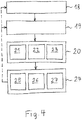
- Fig. 4 shows an embodiment in which first in an optional step (if just required), the focus setting of the camera is set (step: focusing 18), for example, the camera is focused on the outlet nozzle opening 6 or a protective glass 14.
- At least one image is taken with the camera 10 (process step: image acquisition 19).
- the image data are evaluated by an evaluation device 12, wherein at least one actual status feature of the laser processing head 4 is determined on the basis of the image data (method step: evaluation 20).
- the evaluation 20 in the evaluation device 12 can relate, for example, to the following actual status features: the determination 21 of the position of the laser beam (with respect to the outlet nozzle 5) and / or the determination 22 of features relating to the outlet nozzle 5 (eg presence, type, size of the outlet nozzle opening) 6, etc.) and / or the determination 23 of features relating to the protective glass 14 and / or an optical component 15 (eg presence, degree of contamination, etc.).
- control device 13 automatically sets at least one function of the determined actual status feature, in particular as a function of a deviation of the determined actual status feature from a desired status feature and / or as a function of exceeding a predetermined limit value by the determined actual status feature Action 24.
- the setting of an action 24 may be e.g. comprise: an adjustment 25 of the mirror 8 by driving the drive 9 and / or an output 26 of information regarding an actual status feature on an operator interface 16 and / or an interruption 27 of the laser processing operation.
- the actual status feature relates to the position of the laser beam 3 and the action set by the control unit 13 is that a mirror 8 arranged in the laser beam path 7 is moved onto the outlet nozzle 5 for deflecting the laser beam 3, whereby a predetermined , in particular centered, alignment of the laser beam 3 with respect to the outlet nozzle 5 is achieved.
- the image taken by the camera 10 comprises the contour of the outlet nozzle opening 6 and if, depending on a deviation of the actual position of the laser beam 3 from a desired position of the laser beam 3 with respect to the outlet nozzle opening 6, the drive 9 of the mirror 8 is controlled by the control device such that the laser beam 3 assumes the desired position (or this is constantly retraced).
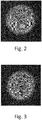
- FIGS. 2 and 3 show image recordings in which the large circle corresponds to the contour of the outlet nozzle opening 6 and the small circle corresponds to the contour of the process zone.
- the process zone is the area where the laser beam 3 meets the workpiece 2 and allows immediate Conclusion on the position of the laser beam 3.
- the jet is arranged decentrally to the nozzle and in Fig. 3 the laser beam 3 is correctly centered.
- the evaluation of the image data in an evaluation device 12 preferably includes an edge detection (using operators or filters), in particular to determine the contour of the outlet nozzle opening 6 and / or the contour of the laser beam 3.
- images are taken continuously with the camera 10 during a laser processing operation or at respective time intervals and that the position of the laser beam 3, if necessary, during the processing operation, preferably in real time, readjusted.
- the actual status feature relates to the presence or type of the outlet nozzle 5 or the size of the outlet nozzle opening 6, the type of outlet nozzle 5 preferably being determined on the basis of the size of the outlet nozzle opening 6. Mistacks can be avoided.
- the actual status feature may also relate to the presence or degree of soiling of an optical component 15 or protective glass 14 arranged behind the outlet nozzle 5, wherein preferably a spatial distribution of the contamination on the optical component 15 or protective glass 14 is determined. This can e.g. in that the degree of soiling in the central area and the degree of soiling in a peripheral area of the optical component 15 or protective glass 14 are determined and optionally related to each other.
- the action set by the control device 13 can output an information relating to the actual status feature to one Be interface 16 for the operator or an interruption of the machining process.
- an internal illumination 17 arranged within the laser processing head 4 can be switched on during the taking of an image by the camera 10 ( Fig. 1 ).
Description
Die Erfindung betrifft eine Laserbearbeitungsvorrichtung nach dem Oberbegriff des Anspruchs 1 und ein Laserbearbeitungsverfahren nach dem Oberbegriff des Anspruch 6 (siehe, z.B.,
Die
Die
Die
The
The
The
Die
Die
Die
Die
Die
Die
Es ist auch bekannt den Laserstrahl über eine manuelle Strahljustage zu positionieren. Die Ist-Position des Laserstrahles wird heute anhand der Lage eines Laser-Einschussloches auf einem vorübergehend angebrachten Klebestreifen an der Austrittsdüse beurteilt.
Die sich aus dem Stand der Technik ergebenden Nachteile bestehen darin, dass eine zuverlässige Bildgebung des auf dem Werkstück auftreffenden Laserstrahles insbesondere in Relation zur Austrittsdüse nicht möglich ist. Bei anderen Systemen bleibt es dem Bedienpersonal vorbehalten, den Laserstrahl per Hand zu positionieren. Ausserdem weisen die im Stand der Technik bekannten Lösungen, die einen Detektor benutzen, einen komplexen Aufbau auf und sind anfällig auf Verschmutzung. Nachteilig bei vielen dieser Lösungen ist auch, dass eine Detektion des Laserstrahles ausserhalb des Laserbearbeitungskopfes erfolgt, womit laterale Positionsverschiebungen des Laser-Spots am Werkstück überhaupt nicht registrierbar sind. Aufgabe der vorliegenden Erfindung ist es somit, diese Nachteile zu beseitigen und eine Laserbearbeitungsvorrichtung bereitzustellen, mit der eine zuverlässige Bildgebung der Austrittsdüse bzw. der Austrittsdüse vorgelagerter transparenter Bauteile erzielt werden kann. Ausserdem soll eine Automatisierung des Laserbearbeitungsvorganges gewährleistet werden, die zur einer optimalen Werkstückbearbeitung führt. Es soll verhindert werden, dass Fehler oder nicht zulässige Betriebszustände, die dem Bereich des Laserbearbeitungskopfes zugeordnet sind, zu einer qualitativ minderwertigen Bearbeitung führen.The
It is also known to position the laser beam via a manual beam adjustment. The actual position of the laser beam is assessed today on the basis of the position of a laser bullet hole on a temporarily attached adhesive strip on the outlet nozzle.
The disadvantages resulting from the prior art are that a reliable imaging of the laser beam impinging on the workpiece, in particular in relation to the outlet nozzle, is not possible. In other systems, it is left to the operator to position the laser beam by hand. In addition, the prior art solutions using a detector are complex in structure and susceptible to contamination. A disadvantage of many of these solutions is also that a detection of the laser beam is outside the laser processing head, so that lateral position shifts of the laser spot on the workpiece are not registered at all. The object of the present invention is thus to eliminate these disadvantages and to provide a laser processing apparatus with which a reliable imaging of the outlet nozzle or of the outlet nozzle upstream of transparent components can be achieved. In addition, an automation of the laser machining process is to be ensured, which leads to an optimal workpiece machining. It is to be prevented that errors or inadmissible operating states, which are assigned to the area of the laser processing head, lead to a qualitatively inferior processing.
Die Aufgabe wird durch die Merkmale der unabhängigen Ansprüche 1 und 6 gelöst. Weitere Merkmale sind in den Zeichnungen und den abhängigen Ansprüchen dargelegt.The object is solved by the features of
Die Lösung der Aufgabe erfolgt also mit einer Laserbearbeitungsvorrichtung zur Bearbeitung eines Werkstückes mit einem Laserstrahl, insbesondere Laserschneidmaschine, umfassend einen Laserbearbeitungskopf mit einer Laser-Austrittsdüse, einen innerhalb des Laserbearbeitungskopfes definierten Laser-Strahlengang, einen einzigen im Laser-Strahlengang angeordneten und bewegbaren Spiegel zur Umlenkung des Laserstrahles auf die Austrittsdüse, und zumindest eine bildgebende Kamera, wobei der Kamera-Strahlengang von innen auf die Austrittsdüse gerichtet und die Kamera mit einer Bilddaten-Auswerteeinrichtung kommunikationsverbunden ist. Der Spiegel ist bewegbar und mit einem Antrieb zum Bewegen des Spiegels kommunikationsverbunden, wobei auch eine Steuereinrichtung mit dem Antrieb des einen Spiegels kommunikationsverbunden ist, wobei die Steuereinrichtung ausgebildet ist, um in Abhängigkeit der von der Auswerteeinrichtung durchgeführten Auswertung der von der Kamera aufgenommenen Bilddaten den Antrieb des Spiegels automatisch zu steuern, wodurch eine vorgegebene, insbesondere zentrierte, Ausrichtung des Laserstrahles lateral in der X-Y-Ebene in Bezug zur Austrittsdüse erzielbar ist.The object is therefore achieved with a laser processing apparatus for processing a workpiece with a laser beam, in particular a laser cutting machine, comprising a laser processing head with a laser exit nozzle, a defined within the laser processing head laser beam path, a single arranged in the laser beam path and movable mirror for deflecting the laser beam to the outlet nozzle, and at least one imaging camera, wherein the camera beam path directed from the inside to the outlet nozzle and the camera is communicatively connected to an image data evaluation device. The mirror is movable and communicatively connected to a drive for moving the mirror, whereby a control device is also communicatively connected to the drive of the one mirror, wherein the control device is designed to drive the drive as a function of the evaluation of the image data recorded by the camera the mirror to be automatically controlled, whereby a predetermined, in particular centered, alignment of the laser beam laterally in the XY plane with respect to the outlet nozzle is achievable.
Erfindungsgemäss ist der Spiegel ein wellenlängenselektiver Spiegel, der für den Laserstrahl im Laser-Strahlengang reflektierend ist und für zumindest einen Wellenlängenbereich des sichtbaren Spektrums durchlässig ist, und dass der Kamera-Strahlengang durch den Spiegel hindurch verläuft, wobei vorzugsweise der Laser-Strahlengang und der Kamera-Strahlengang im Abschnitt zwischen dem Spiegel und der Austrittsdüse überlagern.
Der Vorteil der Erfindung besteht darin, dass durch eine Bilderfassung die Ist-Position des Laserstrahles auf dem Werkstück exakt ermittelt werden kann. Über die Steuereinrichtung kann eine ebenso exakte Korrektur der Strahllage durch Verschwenken des Spiegels erfolgen, wodurch sich eine automatische Regelung ergibt. Diese Anordnung ermöglicht auch die Entkopplung des Laserstrahles von dem von der Kamera aufgenommenen (sichtbaren) Licht. Die Aufnahmen werden durch den in den Laserbearbeitungskopf eingespeisten Laserstrahl nicht beeinflusst, wodurch sich qualitativ hochwertige Bilder ergeben, die einer zuverlässigen Auswertung zugänglich sind.According to the invention, the mirror is a wavelength-selective mirror, which is reflective for the laser beam in the laser beam path and permeable to at least one wavelength range of the visible spectrum, and that the camera beam path passes through the mirror, wherein preferably the laser beam path and the camera Overlay the beam path in the section between the mirror and the outlet nozzle.
The advantage of the invention is that the actual position of the laser beam on the workpiece can be determined exactly by an image acquisition. The control device can be used to correct the jet position by pivoting the mirror, which results in automatic regulation. This arrangement also allows the decoupling of the laser beam from that received by the camera (visible) light. The images are not affected by the laser beam fed into the laser processing head, resulting in high-quality images that are accessible for reliable evaluation.
Der Laserbearbeitungskopf, z.B. Schneidkopf, ist vorzugsweise mit einem motorisch betätigten, dynamischen Schwenkspiegel ausgerüstet. Damit lässt sich der Laserstrahl - relativ zur Austrittsdüse - lateral in der X/Y-Ebene verstellen. Die Kamera ist vorzugsweise innerhalb des Laserbearbeitungskopfes angeordnet. In Kombination mit der Kamera lässt sich eine automatische Strahljustierung, insbesondere Strahlzentrierung, relativ zur Austrittsdüsenöffnung realisieren. Durch Schwenken bzw. Bewegen des Spiegels durch den von der Steuereinrichtung angesteuerten Spiegelantrieb kann der Laserstrahl relativ zur Austrittsdüse exakt ausgerichtet werden.The laser processing head, e.g. Cutting head, is preferably equipped with a motor-operated, dynamic pivoting mirror. This allows the laser beam to be adjusted laterally in the X / Y plane, relative to the exit nozzle. The camera is preferably arranged inside the laser processing head. In combination with the camera, an automatic beam adjustment, in particular beam centering, can be realized relative to the outlet nozzle opening. By pivoting or moving the mirror through the mirror drive controlled by the control device, the laser beam can be exactly aligned relative to the outlet nozzle.
Die Auswerteeinrichtung und die Steuereinrichtung sind ebenfalls miteinander kommunikationsverbunden bzw. bilden ohnedies eine bauliche Einheit.The evaluation device and the control device are also communicatively connected with each other or form a structural unit anyway.
Der Spiegel ist vorzugsweise im visuellen Spektralbereich transmissiv (bevorzugte Ausnahme: Wellenlänge für einen Pilotlaser wird reflektiert) und die Kamera befindet sich hinter dem Spiegel. Während oder vor dem Einstechen und/oder Schneiden wird mit der Kamera die laterale Strahllage kontrolliert und bei Bedarf nachjustiert. Damit ist eine Online-Kontrolle der Strahllage zur Austrittsdüse möglich.The mirror is preferably transmissive in the visual spectral region (preferred exception: wavelength for a pilot laser is reflected) and the camera is behind the mirror. During or before piercing and / or cutting, the lateral beam position is checked with the camera and readjusted if necessary. This allows online control of the jet position to the outlet nozzle.
Für eine kontinuierliche Kontrolle mit Nachführung (closed loop) wird ein hochdynamischer Spiegelantrieb benötigt (> 1 kHz). Eine Offline-Überwachung kann hingegen auch mit einem relativen langsamen Antrieb realisiert werden. Das Kamerasystem kann zusätzlich auch als Monitoring-System verwendet werden. Mit der erfindungsgemässen Anordnung besteht zusätzlich die Möglichkeit, die Grösse der Austrittsdüse zu bestimmen. Damit lässt sich einfach kontrollieren, ob die richtige Düse eingesetzt ist.For continuous control with tracking (closed loop), a highly dynamic mirror drive is required (> 1 kHz). On the other hand, offline monitoring can also be realized with a relatively slow drive. The camera system can also be used as a monitoring system. With the arrangement according to the invention, it is additionally possible to determine the size of the outlet nozzle. This makes it easy to check whether the correct nozzle is used.
Ein Verlust der Düse (abgescherte Sollbruchstelle nach einem Crash oder ausgeklinkte Düse) kann ebenfalls kontrolliert werden. Es besteht auch die Möglichkein - insbesondere in Kombination mit einer Innenbeleuchtung - den Austrittsdüsentyp (verschiedene geometrische Formen) zu bestimmen.A loss of the nozzle (sheared predetermined breaking point after a crash or notched nozzle) can also be controlled. There is also the possibility - especially in combination with an interior lighting - to determine the outlet nozzle type (various geometric shapes).
Mit einem fokussierbaren Kamerasystem kann zusätzlich das Schutzglas oder optische Bauteile im Kamera-Strahlengang überwacht werden. Es ist möglich, die Anwesenheit und den Verschmutzungsgrad zu erfassen. Bekannte Systeme bestimmen den Verschmutzungsgrad anhand der Streustrahlung, anhand der nicht ermittelt werden kann, ob eine Verschmutzung mittig (kritisch) oder eher am Rand (unkritisch) vorliegt. Ein Kamerasystem kann Grösse und Lage der Verschmutzung bestimmen und daraus ableiten, ob dies für den Laserbearbeitungsvorgang nun kritisch oder unkritisch ist. Diese Merkmale erhöhen die Prozessfähigkeit der Laserschneidanlage.With a focusable camera system, it is also possible to monitor the protective glass or optical components in the camera beam path. It is possible to detect the presence and the degree of pollution. Known systems determine the degree of contamination on the basis of the scattered radiation, based on the can not be determined whether a pollution is present in the middle (critical) or rather on the edge (non-critical). A camera system can determine the size and location of the contamination and deduce whether this is critical or uncritical for the laser processing operation. These features increase the process capability of the laser cutting machine.
Bevorzugt wird während oder vor dem Einstechen und/oder Schneiden mit der Kamera die laterale Strahllage kontrolliert und bei Bedarf nachjustiert. Damit ist eine Online-Kontrolle der Strahllage zur Düse möglich.Preferably, the lateral beam position is checked and readjusted during or before piercing and / or cutting with the camera. This allows online control of the jet position to the nozzle.
Die Kamera ist zur Aufnahme von sichtbarem Licht ausgebildet und vorzugsweise oberhalb der Austrittsdüsenöffnung und hinter dem Spiegel angeordnet.The camera is designed to receive visible light and is preferably arranged above the outlet nozzle opening and behind the mirror.
Eine bevorzugte Ausführungsform zeichnet sich dadurch aus, dass die Kamera oberhalb des Spiegels, vorzugsweise in einer Linie mit der Austrittsdüsenöffnung und dem Spiegel, angeordnet ist. Hier befindet sich der Spiegel zwischen Austrittsdüse und Kamera. Der Kamerastrahlengang ist somit nicht umgelenkt, wodurch sich eine kompakte Bauweise ergibt.A preferred embodiment is characterized in that the camera is arranged above the mirror, preferably in a line with the outlet nozzle opening and the mirror. Here is the mirror between the outlet nozzle and the camera. The camera beam path is thus not deflected, resulting in a compact design.
Bevorzugt ist die Kamera innerhalb des Laserbearbeitungskopfes angeordnet, d.h. der Kamerastrahlengang muss nicht aus dem Kopf herausgeführt werden.Preferably, the camera is arranged within the laser processing head, ie the camera beam path does not have to be led out of the head.
Auch der Spiegel samt Antrieb befindet sich innerhalb des Laserbearbeitungskopfes. Der Laserbearbeitungskopf stellt somit ein kompaktes Modul mit weit mehr integrierter Funktionalität dar, als dies bei bekannten Systemen der Fall ist.Also, the mirror and drive is located within the laser processing head. The laser processing head thus represents a compact module with far more integrated functionality than is the case with known systems.
Eine bevorzugte Ausführungsform zeichnet sich dadurch aus, dass der Antrieb des Spiegels ein dynamischer Antrieb ist, dessen Dynamik vorzugsweise zumindest 1 kHz, besonders bevorzugt zumindest 2kHz beträgt. Dies ermöglicht eine Echtzeit-Nachführung des Laserstrahles, wodurch qualitativ hochwertige Schnitte erzielt werden können. Bevorzugt ist der Antrieb ein piezoelektrischer Antrieb.A preferred embodiment is characterized in that the drive of the mirror is a dynamic drive whose dynamics is preferably at least 1 kHz, more preferably at least 2 kHz. This allows for real-time tracking of the laser beam, allowing for high quality cuts. The drive is preferably a piezoelectric drive.
Eine bevorzugte Ausführungsform zeichnet sich dadurch aus, dass die Kamera eine Fokussiereinrichtung umfasst, wobei vorzugsweise die Kamera mit der Fokussiereinrichtung sowohl auf den Bereich der Austrittsdüse als auch auf den Bereich eines hinter der Austrittsdüse angeordneten Schutzglases scharf einstellbar ist.A preferred embodiment is characterized in that the camera comprises a focusing device, wherein preferably the camera with the focusing device is sharply adjustable both on the region of the outlet nozzle and on the region of a protective glass arranged behind the outlet nozzle.
In einer alternativen Ausführungsform umfasst die Laserbearbeitungsvorrichtung zumindest zwei Kameras, wobei eine Kamera auf den Bereich der Austrittsdüse und die andere Kamera auf den Bereich eines hinter der Austrittsdüse angeordneten Schutzglases scharf gestellt ist.In an alternative embodiment, the laser processing device comprises at least two cameras, wherein one camera is focused on the region of the outlet nozzle and the other camera on the region of a protective glass arranged behind the outlet nozzle.
Dadurch kann nicht nur die Austrittsdüse oder der Laserspot am Werkstück erfasst werden, sondern auch Bauteile innerhalb des Laserbearbeitungskopfes überwacht werden. Interessant ist in diesem Zusammenhang insbesondere die Überwachung von Verschmutzungszuständen oder das Vorhandensein dieser Bauteile.As a result, not only the outlet nozzle or the laser spot on the workpiece can be detected, but also components within the laser processing head can be monitored. Of particular interest in this context is the monitoring of soiling conditions or the presence of these components.
Gegebenenfalls kann in zumindest einem Kamerastrahlengang oder in den Strahlengängen der zwei Kameras jeweils ein Strahlteiler angeordnet sein.Optionally, in each case a beam splitter can be arranged in at least one camera beam path or in the beam paths of the two cameras.
Die Aufgabe wird auch mit einem Laserbearbeitungsverfahren, insbesondere Laserschneidverfahren, zum Bearbeiten eines Werkstückes mit einem Laserstrahl erreicht. Dieses wird mit einer Laserbearbeitungsvorrichtung, (insbesondere nach einer der vorhergehenden Ausführungsformen) durchgeführt, die einen Laserbearbeitungskopf mit einer Laser-Austrittsdüse, einen innerhalb des Laserbearbeitungskopfes definierten Laser-Strahlengang und eine bildgebende Kamera umfasst, wobei der Kamera-Strahlengang von innen auf die Austrittsdüse gerichtet ist. Mit der Kamera wird zumindest ein Bild aufgenommen und mit einer Auswerteeinrichtung ausgewertet, wobei anhand der Bilddaten zumindest die Position des Laserstrahls in Bezug auf die Austrittsdüsenöffnung ermittelt wird. In Abhängigkeit dieser Position, insbesondere in Abhängigkeit einer Abweichung von einer Soll-Position und/oder in Abhängigkeit einer Überschreitung eines vorgegebenen Grenzwertes für diese Position, wird automatisch ein einziger im Laser-Strahlengang angeordneter und bewegbarer Spiegel zur Umlenkung des Laserstrahles auf die Austrittsdüse bewegt wird, wodurch eine vorgegebene, insbesondere zentrierte oder sonstige, Ausrichtung des Laserstrahles lateral in der X-Y-Ebene in Bezug zur Austrittsdüse erzielt wird.The object is also achieved with a laser processing method, in particular laser cutting method, for processing a workpiece with a laser beam. This is carried out with a laser processing device (in particular according to one of the preceding embodiments) comprising a laser processing head with a laser exit nozzle, a laser beam path defined within the laser processing head and an imaging camera, the camera beam path directed from the inside onto the exit nozzle is. At least one image is taken with the camera and evaluated with an evaluation device, wherein at least the position of the laser beam with respect to the outlet nozzle opening is determined on the basis of the image data. Depending on this position, in particular as a function of a deviation from a desired position and / or as a function of exceeding a predetermined limit value for this position, a single arranged in the laser beam path and movable mirror for deflecting the laser beam is automatically moved to the outlet nozzle , whereby a predetermined, in particular centered or otherwise, alignment of the laser beam is achieved laterally in the XY plane with respect to the outlet nozzle.
Erfindungsgemäss umfasst das von der Kamera aufgenommene Bild die Kontur der Austrittsdüsenöffnung, und dass in Abhängigkeit einer Abweichung der Ist-Position des Laserstrahles von einer Soll-Position des Laserstrahles in Bezug zur Austrittsdüsenöffnung der Antrieb des Spiegels von der Steuereinrichtung derart gesteuert wird, dass der Laserstrahl die Soll-Position einnimmt.
Dies ermöglicht einerseits eine automatische Überwachung, die im Falle eines unerwünschten Zustandes, eines Fehlers, einer Lageabweichung zu einer Aktion der Steuereinrichtung führt, d.h. es erfolgt eine automatische Reaktion des Systems. Weiters stellt die Austrittsdüsenöffnung eine zuverlässige Referenz dar, die im selben Bild wie der am Werkstück auftreffende Laserstrahl (Spot) enthalten sind. Die Positionsbestimmung wird dadurch höchsten Anforderungen gerecht. Es wird eine automatisierte Justierung des Laserstrahles relativ zur Düsenöffnung durch Ansteuerung des Spiegels erreicht. Die Soll-Position ist vorzugsweise eine in Bezug zur Austrittsdüsenöffnung zentrierte Lage.According to the invention, the image taken by the camera comprises the contour of the outlet nozzle opening, and in dependence on a deviation of the actual position of the laser beam from a desired position of the laser beam with respect to the outlet nozzle opening, the drive of the mirror is controlled by the control device such that the laser beam assumes the target position.
On the one hand, this enables automatic monitoring which, in the case of an undesired state, an error, a positional deviation, leads to an action of the control device, ie an automatic reaction of the system takes place. Furthermore, the exit nozzle opening represents a reliable reference contained in the same image as the laser beam (spot) impinging on the workpiece. Position determination thus meets the highest requirements. There will be an automated adjustment of the Laser beam relative to the nozzle opening achieved by controlling the mirror. The desired position is preferably a centered position with respect to the outlet nozzle opening.
Eine bevorzugte Ausführungsform zeichnet sich dadurch aus, dass die Auswertung der Bilddaten in einer Auswerteeinrichtung eine Kantendetektion umfasst, insbesondere um die Kontur der Austrittsdüsenöffnung und/oder die Kontur des Laserstrahles zu ermitteln. Die Positionsbestimmung kann dadurch sehr genau erfolgen.A preferred embodiment is characterized in that the evaluation of the image data in an evaluation device comprises an edge detection, in particular in order to determine the contour of the outlet nozzle opening and / or the contour of the laser beam. The position determination can be done very accurately.
Eine bevorzugte Ausführungsform zeichnet sich dadurch aus, dass mit der Kamera während eines Laserbearbeitungsvorganges kontinuierlich oder jeweils in Zeitintervallen Aufnahmen gemacht werden und dass die Position des Laserstrahles, falls erforderlich, während des Bearbeitungsvorganges, vorzugsweise in Echtzeit, nachjustiert wird. Prozessbedingte (z.B. zdeitlich abhängige) Abweichungen können dadurch sofort kompensiert werden.A preferred embodiment is characterized in that with the camera during a laser processing operation continuously or in each case in time intervals taken pictures and that the position of the laser beam, if necessary, during the processing operation, preferably in real time, readjusted. Process-related (for example, sometimes dependent) deviations can be compensated for immediately.
Eine bevorzugte Ausführungsform zeichnet sich dadurch aus, dass das Vorhandensein oder der Typ der Austrittsdüse oder die Grösse der Austrittsdüsenöffnung ermittelt wird, wobei vorzugsweise anhand der Grösse der Austrittsdüsenöffnung oder anhand der Innenform der Austrittsdüse der Typ der Austrittsdüse ermittelt wird. Ein Betrieb ohne Düse bzw. mit falscher Düse wird damit von vornherein verhindert.A preferred embodiment is characterized in that the presence or the type of outlet nozzle or the size of the outlet nozzle opening is determined, wherein the type of outlet nozzle is preferably determined on the basis of the size of the outlet nozzle opening or on the basis of the inner shape of the outlet nozzle. Operation without a nozzle or with a wrong nozzle is thus prevented from the outset.
Eine bevorzugte Ausführungsform zeichnet sich dadurch aus, dass das Vorhandensein oder der Verschmutzungsgrad eines hinter der Austrittsdüse angeordneten optischen Bauteiles oder Schutzglases ermittelt wird, wobei vorzugsweise eine räumliche Verteilung der Verschmutzung auf dem optischen Bauteil oder Schutzglas ermittelt wird, z.B. der Verschmutzungsgrad in dem zentralen Bereich und der Verschmutzungsgrad in einem peripheren Bereich des optischen Bauteils oder Schutzglases. Damit können auch andere Bauteile zuverlässig erfasst und in ihrem Zustand überwacht werden.A preferred embodiment is characterized in that the presence or the degree of contamination of an optical component or protective glass arranged behind the outlet nozzle is determined, wherein preferably a spatial distribution of the contamination on the optical component or protective glass is determined, e.g. the degree of soiling in the central area and the degree of soiling in a peripheral area of the optical component or protective glass. This also allows other components to be detected reliably and monitored in their condition.
Eine bevorzugte Ausführungsform zeichnet sich dadurch aus, dass von der Steuereinrichtung eine Ausgabe einer den ermittelten Status betreffenden Information an einer Schnittstelle für das Bedienpersonal (z.B. Bildschirm, akustische Anzeige, Blinklicht, etc.) ist. Das Bedienpersonal kann dadurch sofort benachrichtigt werden, wenn ein Fehler bzw. unzulässiger Zustand eintritt.A preferred embodiment is characterized in that the control device outputs information relating to the determined status to an interface for the operating personnel (for example, screen, audible indicator, flashing light, etc.). The operating personnel can be informed immediately if an error or inadmissible condition occurs.
Eine bevorzugte Ausführungsform zeichnet sich dadurch aus, dass die Steuereinrichtung in Abhängigkeit vom ermittelten Status eine Unterbrechung des Laserbearbeitungsvorganges bewirkt.A preferred embodiment is characterized in that the control device causes an interruption of the laser processing operation in dependence on the determined status.
Eine bevorzugte Ausführungsform zeichnet sich dadurch aus, dass während einer Aufnahme eines Bildes durch die Kamera das Innere des Laserbearbeitungskopfes mittels einer Innenbeleuchtung erleuchtet wird. Dadurch kann die Bildqualität weiter erhöht werden.A preferred embodiment is characterized in that during a recording of an image by the camera, the interior of the laser processing head is illuminated by means of an interior lighting. This can further increase the picture quality.
Vorteilhafte Weiterbildungen sind in den Figuren und in den abhängigen Patentansprüchen dargelegt.Advantageous developments are set forth in the figures and in the dependent claims.
Weitere Vorteile, Merkmale und Einzelheiten der Erfindung ergeben sich aus der nachfolgenden Beschreibung, in der unter Bezugnahme auf die Zeichnungen Ausführungsbeispiele der Erfindung beschrieben sind. Dabei können die in den Ansprüchen und in der Beschreibung erwähnten Merkmale jeweils einzeln für sich oder in beliebiger Kombination erfindungswesentlich sein.Further advantages, features and details of the invention will become apparent from the following description in which embodiments of the invention are described with reference to the drawings. In this case, the features mentioned in the claims and in the description each individually by itself or in any combination essential to the invention.
Die Bezugszeichenliste ist Bestandteil der Offenbarung. Die Figuren werden zusammenhängend und übergreifend beschrieben. Gleiche Bezugszeichen bedeuten gleiche Bauteile, Bezugszeichen mit unterschiedlichen Indices geben funktionsgleiche oder ähnliche Bauteile an.The list of reference numerals is part of the disclosure. The figures are described coherently and comprehensively. The same reference symbols denote the same components, reference symbols with different indices indicate functionally identical or similar components.
Es zeigen dabei:
- Fig. 1
- eine erfindungsgemässe Laserbearbeitungsvorrichtung,
- Fig. 2
- eine Aufnahme eines nicht-zentrierten Laserstrahles,
- Fig. 3
- eine Aufnahme eines in Bezug zur Austrittsdüsenöffnung zentrierten Laserstrahles, und
- Fig. 4
- einen schematischen Verfahrensablauf.
- Fig. 1
- a laser processing device according to the invention,
- Fig. 2
- a photograph of a non-centered laser beam,
- Fig. 3
- a receptacle of a centered with respect to the outlet nozzle opening laser beam, and
- Fig. 4
- a schematic procedure.
Im Laser-Strahlengang 7 ist weiters ein optisches Bauteil 15, z.B. eine Sammellinse, und ein Schutzglas 14 angeordnet, bevor der Laserstrahl durch die Austrittsdüsenöffnung 6 aus dem Laserbearbeitungskopf gelangt. Das Schutzglas 14 verhindert, dass Schmutz und Feuchtigkeit in den Laserbearbeitungskopf 4 dringt.In the
Die Kamera 10 ist mit einer Bilddaten-Auswerteeinrichtung 12 und der Antrieb 9 des Spiegels 8 mit einer Steuereinrichtung 13 kommunikationsverbunden, wobei die Steuereinrichtung 13 ausgebildet ist, um in Abhängigkeit der von der Auswerteeinrichtung 12 durchgeführten Auswertung der von der Kamera 10 aufgenommenen Bilddaten den Antrieb 9 des Spiegels 8 automatisch zu steuern, wodurch eine vorgegebene, insbesondere zentrierte, Ausrichtung des Laserstrahles 3 in Bezug zur Austrittsdüse 5 erzielbar ist.
Die Auswerteeinrichtung 12 und die Steuereinrichtung 13 können eine bauliche Einheit bilden, z.B. in Form eines Steuermoduls oder eines Rechners.The
The
Der Spiegel 8 ist gemäß der Erfindung wellenlängenselektiver Spiegel, der für den Laserstrahl 3 im Laser-Strahlengang 7 reflektierend ist und für zumindest einen Wellenlängenbereich des sichtbaren Spektrums durchlässig ist. Der Kamera-Strahlengang 11 verläuft durch den Spiegel 8 hindurch. Dabei überlagern der Laser-Strahlengang 7 und der Kamera-Strahlengang 11 im Abschnitt zwischen dem Spiegel 8 und der Austrittsdüse 5 miteinander.
Die Kamera 10 ist oberhalb des Spiegels 8 in einer Linie mit der Austrittsdüsenöffnung 6 und dem Spiegel 8 angeordnet.
Der Antrieb 9 des Spiegels 8 ein dynamischer Antrieb, dessen Dynamik vorzugsweise zumindest 1kHz, besonders bevorzugt zumindest 2kHz beträgt.
Die Kamera 10 umfasst vorzugsweise eine Fokussiereinrichtung, mit der die Kamera 10 sowohl auf den Bereich der Austrittsdüse 5 als auch auf den Bereich eines hinter der Austrittsdüse 5 angeordneten Schutzglases 14 scharf einstellbar ist.
Die Steuereinrichtung 13 ist ebenfalls mit einer Schnittstelle 16 für das Bedienpersonal (in Form eines Bildschirmes) verbunden und mit der Laserquelle 28. Die ein Koordinatensystem bildenden Pfeile im unteren Bereich des Bildes deuten an, dass entweder das Werkstück 2 bzw. der Werkstückträger (nicht dargestellt) und/oder Laserbearbeitungskopf bewegbar sind, um z.B. eine Schneidbewegung zu realisieren.The
The
The drive 9 of the
The
The
Im Folgenden wird ein erfindungsgemässes Laserbearbeitungsverfahren, insbesondere Laserschneidverfahren, zum Bearbeiten eines Werkstückes 2 mit einem Laserstrahl 3 beschrieben. Dieses wird mit einer Laserbearbeitungsvorrichtung 1 durchgeführt, die einen Laserbearbeitungskopf 4 mit einer Laser-Austrittsdüse 5, einen innerhalb des Laserbearbeitungskopfes 4 definierten Laser-Strahlengang 7 und eine bildgebende Kamera 10 umfasst, wobei der Kamera-Strahlengang 11 von innen (d.h. von innerhalb des Laserbearbeitungskopfes) auf die Austrittsdüse 5 gerichtet ist.In the following, a laser processing method according to the invention, in particular a laser cutting method, for processing a
Anschliessend wird mit der Kamera 10 zumindest ein Bild aufgenommen (Verfahrensschritt: Bildaufnahme 19). Die Bilddaten werden einer Auswerteeinrichtung 12 ausgewertet, wobei anhand der Bilddaten zumindest ein Ist-Statusmerkmal des Laserbearbeitungskopfes 4 ermittelt wird (Verfahrensschritt: Auswertung 20).Subsequently, at least one image is taken with the camera 10 (process step: image acquisition 19). The image data are evaluated by an
Die Auswertung 20 in der Auswerteeinrichtung 12 kann z.B. folgende Ist-Statusmerkmale betreffen: die Ermittlung 21 der Position des Laserstrahles (in Bezug zur Austrittsdüse 5) und/oder die Ermittlung 22 von Merkmalen betreffend die Austrittsdüse 5 (z.B. Vorhandensein, Typ, Grösse der Austrittsdüsenöffnung 6, etc.) und/oder die Ermittlung 23 von Merkmalen betreffend das Schutzglas 14 und/oder eines optischen Bauteil 15 (z.B. Vorhandensein, Verschmutzungsgrad, etc.).The
In weiterer Folge setzt die Steuereinrichtung 13 in Abhängigkeit des ermittelten Ist-Statusmerkmales, insbesondere in Abhängigkeit einer Abweichung des ermittelten Ist-Statusmerkmales von einem Soll-Statusmerkmal und/oder in Abhängigkeit einer Überschreitung eines vorgegebenen Grenzwertes durch das ermittelte Ist-Statusmerkmal, automatisch zumindest eine Aktion 24.As a result, the
Das Setzen einer Aktion 24 kann z.B. umfassen: eine Verstellung 25 des Spiegels 8 durch Ansteuerung des Antriebes 9 und/oder eine Ausgabe 26 einer Information betreffend ein Ist-Statusmerkmal an einer Bedienschnittstelle 16 und/oder eine Unterbrechung 27 des Laserbearbeitungsvorganges.The setting of an
Daraus ergeben sich folgende bevorzugte Ausführungsformen.This results in the following preferred embodiments.
In einer Ausführungsform betrifft das Ist-Statusmerkmal die Position des Laserstrahles 3 und besteht die durch die Steuereinrichtung 13 gesetzte Aktion darin besteht, dass ein im Laser-Strahlengang 7 angeordneter Spiegel 8 zur Umlenkung des Laserstrahles 3 auf die Austrittsdüse 5 bewegt wird, wodurch eine vorgegebene, insbesondere zentrierte, Ausrichtung des Laserstrahles 3 in Bezug zur Austrittsdüse 5 erzielt wird.In one embodiment, the actual status feature relates to the position of the
Besonders bevorzugt ist, wenn das von der Kamera 10 aufgenommene Bild die Kontur der Austrittsdüsenöffnung 6 umfasst und wenn in Abhängigkeit einer Abweichung der Ist-Position des Laserstrahles 3 von einer Soll-Position des Laserstrahles 3 in Bezug zur Austrittsdüsenöffnung 6 der Antrieb 9 des Spiegels 8 von der Steuereinrichtung derart gesteuert wird, dass der Laserstrahl 3 die Soll-Position einnimmt (oder dieser ständig nachgefahren wird).It is particularly preferred if the image taken by the
Die Auswertung der Bilddaten in einer Auswerteeinrichtung 12 umfasst vorzugsweise eine Kantendetektion (unter Anwendung von Operatoren oder Filtern), insbesondere um die Kontur der Austrittsdüsenöffnung 6 und/oder die Kontur des Laserstrahles 3 zu ermitteln.The evaluation of the image data in an
Bevorzugt ist, wenn mit der Kamera 10 während eines Laserbearbeitungsvorganges kontinuierlich oder jeweils in Zeitintervallen Aufnahmen gemacht werden und dass die Position des Laserstrahles 3, falls erforderlich, während des Bearbeitungsvorganges, vorzugsweise in Echtzeit, nachjustiert wird.It is preferred if images are taken continuously with the
In einer alternativen Ausführungsform des erfindungsgemässen Verfahrens betrifft das Ist-Statusmerkmal das Vorhandensein oder den Typ der Austrittsdüse 5 oder die Grösse der Austrittsdüsenöffnung 6, wobei vorzugsweise anhand der Grösse der Austrittsdüsenöffnung 6 der Typ der Austrittsdüse 5 ermittelt wird. Fehlbestückungen können damit vermieden werden.In an alternative embodiment of the method according to the invention, the actual status feature relates to the presence or type of the
Das Ist-Statusmerkmal kann auch das Vorhandensein oder den Verschmutzungsgrad eines hinter der Austrittsdüse 5 angeordneten optischen Bauteiles 15 oder Schutzglases 14 betreffen, wobei vorzugsweise eine räumliche Verteilung der Verschmutzung auf dem optischen Bauteil 15 oder Schutzglas 14 ermittelt wird. Dies kann z.B. dadurch erfolgen, dass der Verschmutzungsgrad in dem zentralen Bereich und der Verschmutzungsgrad in einem peripheren Bereich des optischen Bauteils 15 oder Schutzglases 14 bestimmt und gegebenenfalls zueinander in Beziehung gesetzt wird.The actual status feature may also relate to the presence or degree of soiling of an
Wie bereits erwähnt kann die von der Steuereinrichtung 13 gesetzte Aktion eine Ausgabe einer das Ist-Statusmerkmal betreffenden Information an einer Schnittstelle 16 für das Bedienpersonal sein oder eine Unterbrechung des Bearbeitungsvorganges.As already mentioned, the action set by the
Um die Bildqualität zu erhöhen kann während einer Aufnahme eines Bildes durch die Kamera 10 eine innerhalb des Laserbearbeitungskopfes 4 angeordnete Innenbeleuchtung 17 eingeschaltet sein (
- 1 Laserbearbeitungsvorrichtung1 laser processing device
- 2 Werkstück2 workpiece
- 3 Laserstrahl3 laser beam
- 4 Laserbearbeitungskopf4 laser processing head
- 5 Laser-Austrittsdüse5 laser outlet nozzle
- 6 Austrittsdüsenöffnung6 outlet nozzle opening
- 7 Laser-Strahlengang7 laser beam path
- 8 Spiegel8 mirrors
- 9 Antrieb9 drive
- 10 Kamera10 camera
- 11 Kamera-Strahlengang11 camera beam path
- 12 Bilddaten-Auswerteeinrichtung12 image data evaluation device
- 13 Steuereinrichtung13 control device
- 14 Schutzglas14 protective glass
- 15 Optisches Bauteil15 Optical component
- 16 Schnittstelle für das Bedienpersonal16 Interface for the operating personnel
- 17 Innenbeleuchtung17 interior lighting
- 18 Verfahrensschritt: Fokussieren18 Step: Focusing
- 19 Verfahrensschritt: Bildaufnahme19 Process step: image acquisition
- 20 Verfahrensschritt: Auswertung20 Process step: evaluation
- 21 Ermittlung: Position des Laserstrahles21 determination: position of the laser beam
- 22 Ermittlung: Austrittsdüse22 Determination: outlet nozzle
- 23 Ermittlung: Schutzglas/optisches Bauteil23 Determination: protective glass / optical component
- 24 Setzen einer Aktion durch die Steuereinrichtung24 Set an action by the controller
- 25 Aktion: Verstellung des Spiegels25 Action: Adjustment of the mirror
- 26 Aktion: Ausgabe einer Information26 Action: Output of information
- 27 Aktion: Unterbrechung des Laserbearbeitungsvorganges27 Action: Interruption of the laser processing process
- 28 Laserquelle28 laser source
Claims (13)
- A laser machining device (1) for machining a workpiece (2) with a laser beam (3), in particular a laser cutting machine, comprising a laser machining head (4) with a laser outlet nozzle (5), a laser beam path (7) defined within the laser machining head (4), a mirror (8) arranged and moveable within the laser beam path (7) for deflecting the laser beam (3) towards the outlet nozzle (5), and at least one imaging camera (10), wherein the camera beam path (11) is directed from the inside towards the outlet nozzle (5) and the camera has a communication link with an image data evaluation device (12), wherein the mirror (8) has a communication link with a drive (9) for moving the mirror (8), that a control device (13) has a communication link with the drive (9) of the one mirror (8), wherein the control device (13) is designed to automatically control the drive (9) of the mirror (8) in dependence of the evaluation carried out by the evaluation device (12), of the image data recorded by the camera (10), whereby a prescribed, in particular centred, orientation of the laser beam (3), laterally in the X-Y plane in relation to the outlet nozzle (5), is achievable, characterised in that
the laser machining device (1) comprises a single mirror (8) wherein the moveable mirror (8) is a wavelength-selective mirror which works as a reflector for the laser beam (3) in the laser beam path (7) and is permeable for at least one wavelength range of the visible spectrum, and that the camera beam path (11) runs through the mirror (8), wherein preferably the laser beam path (7) and the camera beam path (11) overlap in the section between the mirror (8) and the outlet nozzle (5). - The laser machining device according to claim 1, characterised in that the camera (10) is arranged above the mirror (8), preferably in one line with the nozzle outlet opening (6) and the mirror (8).
- The laser machining device according to one of claims 1 or 2, characterised in that the drive (9) of the mirror (8) is a dynamic drive, the dynamic of which preferably amounts to at least 1kHz, particularly preferably at least 2kHz.
- The laser machining device according to one of claims 1 to 3, characterised in that the camera (10) comprises a focussing device, wherein the camera (10), by means of the focussing device, may preferably be sharply focussed towards the area of the nozzle outlet (5) as well as towards the area in which a protective/safety glass (14) is arranged behind the nozzle outlet (5).
- The laser machining device according to one of claims 1 to 3, characterised in that the laser machining device (1) comprises as least two cameras, wherein one camera may be sharply focussed toward the area of the nozzle outlet (5) and the other camera, toward the area of a protective glass (14) arranged behind the nozzle outlet (5), wherein if necessary a beam splitter is arranged in at least one camera beam path.
- A laser machining method, in particular a laser cutting method, for machining a workpiece (2) with a laser beam (3), with a laser machining device (1), in particular according to one of the preceding claims, comprising a laser machining head (4) with a laser nozzle outlet (5), a laser beam path (7) defined inside the laser machining head (4) and an imaging camera (10), characterised in that the camera beam path (11) is directed from the inside toward the nozzle outlet (5) through a single wavelength-selective mirror (8) arranged and moveable within the laser beam path, wherein at least one image is recorded by the camera (10) and evaluated by an evaluation device (12), wherein by means of the image data at least the position of the laser beam (3) in relation to the outlet nozzle opening (6) is determined, and wherein in dependence of a deviation from a set position, the mirror (8) is automatically moved in order to deflect the laser beam (3) towards the nozzle outlet (5), whereby a prescribed, in particular centred or other, orientation of the laser beam (3) laterally in the X-Y plane in relation to the outlet nozzle (5) is achieved, wherein the image recorded by the camera (10) comprises the contour of the nozzle outlet opening (6) and that, in dependence of a deviation of the actual position of the laser beam (3) from the set position of the laser beam (3) in relation to the nozzle outlet opening (6), the drive (9) of the mirror (8) is controlled by the control device so that the laser beam (3) takes up the set position.
- The laser machining method according to claim 6, characterised in that the evaluation of the image data in an evaluation device (12) comprises an edge detection, in particular in order to determine the contour of the nozzle outlet opening (6) and/or the contour of the laser beam (3).
- The laser machining method according to claims 6 or 7, characterised in that pictures are taken with the camera (10) continuously or at intervals during a laser machining process and that, if necessary, the position of the laser beam (3) may be readjusted during the machining process, preferably in real time.
- The laser machining method according to one of claims 6 to 8, characterised in that the presence or the type of the nozzle outlet (5) or the size of the nozzle outlet opening (6) is determined, wherein the type of nozzle outlet (5) is determined preferably on the basis of the size of the nozzle outlet opening (6) or on the basis of the inner shape of the nozzle outlet (5).
- The laser machining method according to one of claims 6 to 9, characterised in that the presence or the degree of contamination of an optical component (15) or protective glass (14) arranged behind the outlet nozzle (5) is determined, wherein preferably a spatial distribution of the contamination on the optical component (15) or protective glass (14) is determined, for example the degree of contamination in the central area and the degree of contamination in a peripheral area of the optical component (15) or protective glass (14).
- The laser machining method according to one of claims 6 to 10, characterised in that information is output by the control device (13) concerning the determined status at an interface (16) for the operating personnel.
- The laser machining method according to one of claims 6 to 11, characterised in that, in dependence of the determined status, the control device (13) effects an interruption in the laser machining process.
- The laser machining method according to one of claims 6 to 12, characterised in that the interior of the laser machining head (4) is illuminated by means of an interior light (17) during the taking of a picture by the camera (10).
Priority Applications (2)
| Application Number | Priority Date | Filing Date | Title |
|---|---|---|---|
| PL14150430T PL2894004T3 (en) | 2014-01-08 | 2014-01-08 | Device for laser machining with a camera and a movavble mirror |
| EP14150430.8A EP2894004B1 (en) | 2014-01-08 | 2014-01-08 | Device for laser machining with a camera and a movavble mirror |
Applications Claiming Priority (1)
| Application Number | Priority Date | Filing Date | Title |
|---|---|---|---|
| EP14150430.8A EP2894004B1 (en) | 2014-01-08 | 2014-01-08 | Device for laser machining with a camera and a movavble mirror |
Publications (2)
| Publication Number | Publication Date |
|---|---|
| EP2894004A1 EP2894004A1 (en) | 2015-07-15 |
| EP2894004B1 true EP2894004B1 (en) | 2017-10-25 |
Family
ID=49916982
Family Applications (1)
| Application Number | Title | Priority Date | Filing Date |
|---|---|---|---|
| EP14150430.8A Active EP2894004B1 (en) | 2014-01-08 | 2014-01-08 | Device for laser machining with a camera and a movavble mirror |
Country Status (2)
| Country | Link |
|---|---|
| EP (1) | EP2894004B1 (en) |
| PL (1) | PL2894004T3 (en) |
Cited By (2)
| Publication number | Priority date | Publication date | Assignee | Title |
|---|---|---|---|---|
| EP3517241A1 (en) | 2018-01-29 | 2019-07-31 | Bystronic Laser AG | Optical device for shaping an electromagnetic wave beam and use thereof, beam treatment device and use thereof, and beam treatment method |
| EP3984687A1 (en) | 2020-10-16 | 2022-04-20 | Bystronic Laser AG | Beam processing head and beam processing method |
Families Citing this family (6)
| Publication number | Priority date | Publication date | Assignee | Title |
|---|---|---|---|---|
| DE102017213511A1 (en) | 2017-08-03 | 2019-02-07 | Trumpf Werkzeugmaschinen Gmbh + Co. Kg | Process for laser material processing and laser machine |
| JP6680751B2 (en) | 2017-11-24 | 2020-04-15 | ファナック株式会社 | Laser processing equipment that warns of dirt on the protective window during laser processing |
| DE102018107666A1 (en) * | 2018-03-29 | 2019-10-02 | Alpha Laser Gmbh | Workpiece processing by means of laser radiation |
| CN112705838A (en) * | 2019-10-09 | 2021-04-27 | Nps株式会社 | Laser device |
| US20210121980A1 (en) * | 2019-10-23 | 2021-04-29 | Nps Co.,Ltd. | Laser apparatus |
| WO2022050436A1 (en) * | 2020-09-03 | 2022-03-10 | 엘지전자 주식회사 | Laser processing apparatus |
Citations (1)
| Publication number | Priority date | Publication date | Assignee | Title |
|---|---|---|---|---|
| US5449882A (en) * | 1993-03-15 | 1995-09-12 | Reliant Laser Corporation | Mirror-based laser-processing system with temperature and position control of moving laser spot |
Family Cites Families (10)
| Publication number | Priority date | Publication date | Assignee | Title |
|---|---|---|---|---|
| DE3339318C2 (en) | 1983-10-29 | 1995-05-24 | Trumpf Gmbh & Co | Laser processing machine |
| DE3406677A1 (en) | 1984-02-24 | 1985-09-05 | Fa. Carl Zeiss, 7920 Heidenheim | DEVICE FOR COMPENSATING THE EMISSION OF A LASER BEAM |
| JPH04118193A (en) * | 1990-09-04 | 1992-04-20 | Hitachi Constr Mach Co Ltd | Device for monitoring protective glass of laser beam machine |
| JP3761657B2 (en) * | 1997-03-10 | 2006-03-29 | 株式会社アマダ | Laser processing method and apparatus |
| EP1716963B1 (en) | 2005-04-26 | 2008-10-22 | Highyag Lasertechnologie GmbH | Optical arrangement for remote laser machining which creates a 3D working area |
| EP1728582A1 (en) | 2005-05-31 | 2006-12-06 | Trumpf Laser- und Systemtechnik GmbH | Device for detecting of modifications of a laser beam |
| DE102007013623A1 (en) * | 2007-03-21 | 2008-10-02 | Trumpf Werkzeugmaschinen Gmbh + Co. Kg | Method for aligning a laser beam passing through an opening of a bore of a laser processing nozzle on a laser processing head comprises activating the beam with a defined energy, passing the beam along a first line and further processing |
| DE102009007769B4 (en) | 2009-02-05 | 2016-07-14 | Jenoptik Automatisierungstechnik Gmbh | Laser processing head with integrated sensor device for focus position monitoring |
| EP2585975B1 (en) | 2010-06-28 | 2018-03-21 | Precitec GmbH & Co. KG | A method for classifying a multitude of images recorded by a camera observing a processing area and laser material processing head using the same |
| DE102011004117A1 (en) | 2011-02-15 | 2012-08-16 | Trumpf Laser- Und Systemtechnik Gmbh | Method for controlling a cutting operation on a workpiece |
-
2014
- 2014-01-08 PL PL14150430T patent/PL2894004T3/en unknown
- 2014-01-08 EP EP14150430.8A patent/EP2894004B1/en active Active
Patent Citations (1)
| Publication number | Priority date | Publication date | Assignee | Title |
|---|---|---|---|---|
| US5449882A (en) * | 1993-03-15 | 1995-09-12 | Reliant Laser Corporation | Mirror-based laser-processing system with temperature and position control of moving laser spot |
Cited By (4)
| Publication number | Priority date | Publication date | Assignee | Title |
|---|---|---|---|---|
| EP3517241A1 (en) | 2018-01-29 | 2019-07-31 | Bystronic Laser AG | Optical device for shaping an electromagnetic wave beam and use thereof, beam treatment device and use thereof, and beam treatment method |
| WO2019145536A1 (en) | 2018-01-29 | 2019-08-01 | Bystronic Laser Ag | Optical device for shaping an electromagnetic wave beam and use thereof, beam treatment device and use thereof, and beam treatment method |
| EP3984687A1 (en) | 2020-10-16 | 2022-04-20 | Bystronic Laser AG | Beam processing head and beam processing method |
| WO2022079239A1 (en) | 2020-10-16 | 2022-04-21 | Bystronic Laser Ag | Beam machining head and method for beam machining |
Also Published As
| Publication number | Publication date |
|---|---|
| PL2894004T3 (en) | 2018-04-30 |
| EP2894004A1 (en) | 2015-07-15 |
Similar Documents
| Publication | Publication Date | Title |
|---|---|---|
| EP2894004B1 (en) | Device for laser machining with a camera and a movavble mirror | |
| EP1640101B1 (en) | Method for controlling an automated machining process | |
| EP2726244B1 (en) | Method of detecting defects in a non-linear weld seam or a non-linear cutting gap during a laser-machining process ; corresponding laser-machining device | |
| EP3838472B1 (en) | Deflection unit with two windows, one optical element and a xy deflection device | |
| EP2544849B1 (en) | Laser machning head und method of machining a workpiece using a laser beam | |
| EP3159093B1 (en) | Method of controlling a laser cuting process in a high energy zone with interruption of the cutting process ; corresponding device and computer program | |
| DE102015012565B3 (en) | Device and method for increasing the accuracy of an OCT measuring system for laser material processing | |
| EP3294488B1 (en) | Laser cutting device with an observation system | |
| DE4336136C2 (en) | Laser processing device and method | |
| DE102014000330B3 (en) | Method for monitoring and controlling the focus position of a laser beam during laser cutting | |
| DE10297255B4 (en) | Method and device for monitoring and adjusting a laser welding process | |
| DE102013209526B4 (en) | Method, computer program product and device for detecting a cut-off | |
| DE102013226961B4 (en) | Test device and method for computer-aided monitoring of a attached to a processing optics tool part of a device for material processing and apparatus for computer-aided material processing | |
| EP3313607B1 (en) | Laser machining head and machine comprising said head | |
| EP3102361B1 (en) | Method for identifying an edge contour of an opening on a machining head, and machining tool | |
| DE102020000630B4 (en) | Method and device for performing and monitoring a machining process for a workpiece | |
| EP3883719A1 (en) | Method for cutting a workpiece by means of a laser beam, and laser machining system for carrying out the method | |
| WO2021140037A1 (en) | Method for the automated beam positioning of a laser beam in relation to a nozzle of a laser processing head, and laser processing system for processing a workpiece using a laser beam | |
| DE102020110087A1 (en) | PROCESS FOR PROCESS CONTROL IN LASER MATERIAL PROCESSING | |
| DE102017009559B4 (en) | Measuring device for monitoring, system for processing and monitoring, and method for monitoring | |
| DE102020211533B3 (en) | Measuring instrument for a laser tool, laser tool and workpiece processing device, and method for measuring a distance | |
| WO2023135226A2 (en) | Process-monitoring module for monitoring a laser machining process, and laser machining system comprising same | |
| DE102022106605A1 (en) | Laser processing method and laser processing machine |
Legal Events
| Date | Code | Title | Description |
|---|---|---|---|
| PUAI | Public reference made under article 153(3) epc to a published international application that has entered the european phase |
Free format text: ORIGINAL CODE: 0009012 |
|
| 17P | Request for examination filed |
Effective date: 20140108 |
|
| AK | Designated contracting states |
Kind code of ref document: A1 Designated state(s): AL AT BE BG CH CY CZ DE DK EE ES FI FR GB GR HR HU IE IS IT LI LT LU LV MC MK MT NL NO PL PT RO RS SE SI SK SM TR |
|
| AX | Request for extension of the european patent |
Extension state: BA ME |
|
| R17P | Request for examination filed (corrected) |
Effective date: 20160115 |
|
| RBV | Designated contracting states (corrected) |
Designated state(s): AL AT BE BG CH CY CZ DE DK EE ES FI FR GB GR HR HU IE IS IT LI LT LU LV MC MK MT NL NO PL PT RO RS SE SI SK SM TR |
|
| 17Q | First examination report despatched |
Effective date: 20160708 |
|
| STAA | Information on the status of an ep patent application or granted ep patent |
Free format text: STATUS: EXAMINATION IS IN PROGRESS |
|
| GRAP | Despatch of communication of intention to grant a patent |
Free format text: ORIGINAL CODE: EPIDOSNIGR1 |
|
| STAA | Information on the status of an ep patent application or granted ep patent |
Free format text: STATUS: GRANT OF PATENT IS INTENDED |
|
| INTG | Intention to grant announced |
Effective date: 20170412 |
|
| GRAJ | Information related to disapproval of communication of intention to grant by the applicant or resumption of examination proceedings by the epo deleted |
Free format text: ORIGINAL CODE: EPIDOSDIGR1 |
|
| STAA | Information on the status of an ep patent application or granted ep patent |
Free format text: STATUS: EXAMINATION IS IN PROGRESS |
|
| GRAP | Despatch of communication of intention to grant a patent |
Free format text: ORIGINAL CODE: EPIDOSNIGR1 |
|
| STAA | Information on the status of an ep patent application or granted ep patent |
Free format text: STATUS: GRANT OF PATENT IS INTENDED |
|
| INTC | Intention to grant announced (deleted) | ||
| INTG | Intention to grant announced |
Effective date: 20170810 |
|
| GRAS | Grant fee paid |
Free format text: ORIGINAL CODE: EPIDOSNIGR3 |
|
| GRAA | (expected) grant |
Free format text: ORIGINAL CODE: 0009210 |
|
| STAA | Information on the status of an ep patent application or granted ep patent |
Free format text: STATUS: THE PATENT HAS BEEN GRANTED |
|
| AK | Designated contracting states |
Kind code of ref document: B1 Designated state(s): AL AT BE BG CH CY CZ DE DK EE ES FI FR GB GR HR HU IE IS IT LI LT LU LV MC MK MT NL NO PL PT RO RS SE SI SK SM TR |
|
| REG | Reference to a national code |
Ref country code: GB Ref legal event code: FG4D Free format text: NOT ENGLISH |
|
| REG | Reference to a national code |
Ref country code: CH Ref legal event code: EP |
|
| REG | Reference to a national code |
Ref country code: AT Ref legal event code: REF Ref document number: 939468 Country of ref document: AT Kind code of ref document: T Effective date: 20171115 |
|
| REG | Reference to a national code |
Ref country code: IE Ref legal event code: FG4D Free format text: LANGUAGE OF EP DOCUMENT: GERMAN |
|
| REG | Reference to a national code |
Ref country code: DE Ref legal event code: R096 Ref document number: 502014005926 Country of ref document: DE |
|
| REG | Reference to a national code |
Ref country code: FR Ref legal event code: PLFP Year of fee payment: 5 |
|
| REG | Reference to a national code |
Ref country code: NL Ref legal event code: MP Effective date: 20171025 |
|
| REG | Reference to a national code |
Ref country code: LT Ref legal event code: MG4D |
|
| PG25 | Lapsed in a contracting state [announced via postgrant information from national office to epo] |
Ref country code: NL Free format text: LAPSE BECAUSE OF FAILURE TO SUBMIT A TRANSLATION OF THE DESCRIPTION OR TO PAY THE FEE WITHIN THE PRESCRIBED TIME-LIMIT Effective date: 20171025 |
|
| PG25 | Lapsed in a contracting state [announced via postgrant information from national office to epo] |
Ref country code: ES Free format text: LAPSE BECAUSE OF FAILURE TO SUBMIT A TRANSLATION OF THE DESCRIPTION OR TO PAY THE FEE WITHIN THE PRESCRIBED TIME-LIMIT Effective date: 20171025 Ref country code: FI Free format text: LAPSE BECAUSE OF FAILURE TO SUBMIT A TRANSLATION OF THE DESCRIPTION OR TO PAY THE FEE WITHIN THE PRESCRIBED TIME-LIMIT Effective date: 20171025 Ref country code: NO Free format text: LAPSE BECAUSE OF FAILURE TO SUBMIT A TRANSLATION OF THE DESCRIPTION OR TO PAY THE FEE WITHIN THE PRESCRIBED TIME-LIMIT Effective date: 20180125 Ref country code: LT Free format text: LAPSE BECAUSE OF FAILURE TO SUBMIT A TRANSLATION OF THE DESCRIPTION OR TO PAY THE FEE WITHIN THE PRESCRIBED TIME-LIMIT Effective date: 20171025 Ref country code: SE Free format text: LAPSE BECAUSE OF FAILURE TO SUBMIT A TRANSLATION OF THE DESCRIPTION OR TO PAY THE FEE WITHIN THE PRESCRIBED TIME-LIMIT Effective date: 20171025 |
|
| PG25 | Lapsed in a contracting state [announced via postgrant information from national office to epo] |
Ref country code: GR Free format text: LAPSE BECAUSE OF FAILURE TO SUBMIT A TRANSLATION OF THE DESCRIPTION OR TO PAY THE FEE WITHIN THE PRESCRIBED TIME-LIMIT Effective date: 20180126 Ref country code: LV Free format text: LAPSE BECAUSE OF FAILURE TO SUBMIT A TRANSLATION OF THE DESCRIPTION OR TO PAY THE FEE WITHIN THE PRESCRIBED TIME-LIMIT Effective date: 20171025 Ref country code: HR Free format text: LAPSE BECAUSE OF FAILURE TO SUBMIT A TRANSLATION OF THE DESCRIPTION OR TO PAY THE FEE WITHIN THE PRESCRIBED TIME-LIMIT Effective date: 20171025 Ref country code: IS Free format text: LAPSE BECAUSE OF FAILURE TO SUBMIT A TRANSLATION OF THE DESCRIPTION OR TO PAY THE FEE WITHIN THE PRESCRIBED TIME-LIMIT Effective date: 20180225 Ref country code: BG Free format text: LAPSE BECAUSE OF FAILURE TO SUBMIT A TRANSLATION OF THE DESCRIPTION OR TO PAY THE FEE WITHIN THE PRESCRIBED TIME-LIMIT Effective date: 20180125 Ref country code: RS Free format text: LAPSE BECAUSE OF FAILURE TO SUBMIT A TRANSLATION OF THE DESCRIPTION OR TO PAY THE FEE WITHIN THE PRESCRIBED TIME-LIMIT Effective date: 20171025 |
|
| REG | Reference to a national code |
Ref country code: DE Ref legal event code: R097 Ref document number: 502014005926 Country of ref document: DE |
|
| PG25 | Lapsed in a contracting state [announced via postgrant information from national office to epo] |
Ref country code: CZ Free format text: LAPSE BECAUSE OF FAILURE TO SUBMIT A TRANSLATION OF THE DESCRIPTION OR TO PAY THE FEE WITHIN THE PRESCRIBED TIME-LIMIT Effective date: 20171025 Ref country code: SK Free format text: LAPSE BECAUSE OF FAILURE TO SUBMIT A TRANSLATION OF THE DESCRIPTION OR TO PAY THE FEE WITHIN THE PRESCRIBED TIME-LIMIT Effective date: 20171025 Ref country code: DK Free format text: LAPSE BECAUSE OF FAILURE TO SUBMIT A TRANSLATION OF THE DESCRIPTION OR TO PAY THE FEE WITHIN THE PRESCRIBED TIME-LIMIT Effective date: 20171025 Ref country code: CY Free format text: LAPSE BECAUSE OF FAILURE TO SUBMIT A TRANSLATION OF THE DESCRIPTION OR TO PAY THE FEE WITHIN THE PRESCRIBED TIME-LIMIT Effective date: 20171025 Ref country code: EE Free format text: LAPSE BECAUSE OF FAILURE TO SUBMIT A TRANSLATION OF THE DESCRIPTION OR TO PAY THE FEE WITHIN THE PRESCRIBED TIME-LIMIT Effective date: 20171025 |
|
| PG25 | Lapsed in a contracting state [announced via postgrant information from national office to epo] |
Ref country code: RO Free format text: LAPSE BECAUSE OF FAILURE TO SUBMIT A TRANSLATION OF THE DESCRIPTION OR TO PAY THE FEE WITHIN THE PRESCRIBED TIME-LIMIT Effective date: 20171025 Ref country code: SM Free format text: LAPSE BECAUSE OF FAILURE TO SUBMIT A TRANSLATION OF THE DESCRIPTION OR TO PAY THE FEE WITHIN THE PRESCRIBED TIME-LIMIT Effective date: 20171025 |
|
| PLBE | No opposition filed within time limit |
Free format text: ORIGINAL CODE: 0009261 |
|
| STAA | Information on the status of an ep patent application or granted ep patent |
Free format text: STATUS: NO OPPOSITION FILED WITHIN TIME LIMIT |
|
| PG25 | Lapsed in a contracting state [announced via postgrant information from national office to epo] |
Ref country code: MT Free format text: LAPSE BECAUSE OF FAILURE TO SUBMIT A TRANSLATION OF THE DESCRIPTION OR TO PAY THE FEE WITHIN THE PRESCRIBED TIME-LIMIT Effective date: 20171025 |
|
| 26N | No opposition filed |
Effective date: 20180726 |
|
| PG25 | Lapsed in a contracting state [announced via postgrant information from national office to epo] |
Ref country code: LU Free format text: LAPSE BECAUSE OF NON-PAYMENT OF DUE FEES Effective date: 20180108 |
|
| REG | Reference to a national code |
Ref country code: IE Ref legal event code: MM4A |
|
| PG25 | Lapsed in a contracting state [announced via postgrant information from national office to epo] |
Ref country code: SI Free format text: LAPSE BECAUSE OF FAILURE TO SUBMIT A TRANSLATION OF THE DESCRIPTION OR TO PAY THE FEE WITHIN THE PRESCRIBED TIME-LIMIT Effective date: 20171025 |
|
| PG25 | Lapsed in a contracting state [announced via postgrant information from national office to epo] |
Ref country code: IE Free format text: LAPSE BECAUSE OF NON-PAYMENT OF DUE FEES Effective date: 20180108 |
|
| PG25 | Lapsed in a contracting state [announced via postgrant information from national office to epo] |
Ref country code: MC Free format text: LAPSE BECAUSE OF FAILURE TO SUBMIT A TRANSLATION OF THE DESCRIPTION OR TO PAY THE FEE WITHIN THE PRESCRIBED TIME-LIMIT Effective date: 20171025 |
|
| REG | Reference to a national code |
Ref country code: AT Ref legal event code: MM01 Ref document number: 939468 Country of ref document: AT Kind code of ref document: T Effective date: 20190108 |
|
| PG25 | Lapsed in a contracting state [announced via postgrant information from national office to epo] |
Ref country code: AT Free format text: LAPSE BECAUSE OF NON-PAYMENT OF DUE FEES Effective date: 20190108 |
|
| PG25 | Lapsed in a contracting state [announced via postgrant information from national office to epo] |
Ref country code: PT Free format text: LAPSE BECAUSE OF FAILURE TO SUBMIT A TRANSLATION OF THE DESCRIPTION OR TO PAY THE FEE WITHIN THE PRESCRIBED TIME-LIMIT Effective date: 20171025 |
|
| PG25 | Lapsed in a contracting state [announced via postgrant information from national office to epo] |
Ref country code: MK Free format text: LAPSE BECAUSE OF NON-PAYMENT OF DUE FEES Effective date: 20171025 Ref country code: HU Free format text: LAPSE BECAUSE OF FAILURE TO SUBMIT A TRANSLATION OF THE DESCRIPTION OR TO PAY THE FEE WITHIN THE PRESCRIBED TIME-LIMIT; INVALID AB INITIO Effective date: 20140108 |
|
| PG25 | Lapsed in a contracting state [announced via postgrant information from national office to epo] |
Ref country code: AL Free format text: LAPSE BECAUSE OF FAILURE TO SUBMIT A TRANSLATION OF THE DESCRIPTION OR TO PAY THE FEE WITHIN THE PRESCRIBED TIME-LIMIT Effective date: 20171025 |
|
| PGFP | Annual fee paid to national office [announced via postgrant information from national office to epo] |
Ref country code: PL Payment date: 20221203 Year of fee payment: 10 Ref country code: BE Payment date: 20221216 Year of fee payment: 10 |
|
| PGFP | Annual fee paid to national office [announced via postgrant information from national office to epo] |
Ref country code: CH Payment date: 20230106 Year of fee payment: 10 |
|
| PGFP | Annual fee paid to national office [announced via postgrant information from national office to epo] |
Ref country code: TR Payment date: 20230106 Year of fee payment: 10 Ref country code: IT Payment date: 20221213 Year of fee payment: 10 Ref country code: DE Payment date: 20221207 Year of fee payment: 10 |
|
| P01 | Opt-out of the competence of the unified patent court (upc) registered |
Effective date: 20230522 |
|
| PGFP | Annual fee paid to national office [announced via postgrant information from national office to epo] |
Ref country code: GB Payment date: 20231207 Year of fee payment: 11 |
|
| PGFP | Annual fee paid to national office [announced via postgrant information from national office to epo] |
Ref country code: FR Payment date: 20231222 Year of fee payment: 11 |
|
| PGFP | Annual fee paid to national office [announced via postgrant information from national office to epo] |
Ref country code: BE Payment date: 20231219 Year of fee payment: 11 |