EP0147496A1 - Dispositif pour assembler des contrefiches aux montants d'un échafaudage modulaire - Google Patents
Dispositif pour assembler des contrefiches aux montants d'un échafaudage modulaire Download PDFInfo
- Publication number
- EP0147496A1 EP0147496A1 EP84100078A EP84100078A EP0147496A1 EP 0147496 A1 EP0147496 A1 EP 0147496A1 EP 84100078 A EP84100078 A EP 84100078A EP 84100078 A EP84100078 A EP 84100078A EP 0147496 A1 EP0147496 A1 EP 0147496A1
- Authority
- EP
- European Patent Office
- Prior art keywords
- support bracket
- connecting member
- scaffolding
- pin
- stand
- Prior art date
- Legal status (The legal status is an assumption and is not a legal conclusion. Google has not performed a legal analysis and makes no representation as to the accuracy of the status listed.)
- Withdrawn
Links
Images

Classifications
-
- E—FIXED CONSTRUCTIONS
- E04—BUILDING
- E04G—SCAFFOLDING; FORMS; SHUTTERING; BUILDING IMPLEMENTS OR AIDS, OR THEIR USE; HANDLING BUILDING MATERIALS ON THE SITE; REPAIRING, BREAKING-UP OR OTHER WORK ON EXISTING BUILDINGS
- E04G7/00—Connections between parts of the scaffold
- E04G7/30—Scaffolding bars or members with non-detachably fixed coupling elements
- E04G7/302—Scaffolding bars or members with non-detachably fixed coupling elements for connecting crossing or intersecting bars or members
- E04G7/306—Scaffolding bars or members with non-detachably fixed coupling elements for connecting crossing or intersecting bars or members the added coupling elements are fixed at several bars or members to connect
- E04G7/308—Scaffolding bars or members with non-detachably fixed coupling elements for connecting crossing or intersecting bars or members the added coupling elements are fixed at several bars or members to connect without tying means for connecting the bars or members
-
- E—FIXED CONSTRUCTIONS
- E04—BUILDING
- E04G—SCAFFOLDING; FORMS; SHUTTERING; BUILDING IMPLEMENTS OR AIDS, OR THEIR USE; HANDLING BUILDING MATERIALS ON THE SITE; REPAIRING, BREAKING-UP OR OTHER WORK ON EXISTING BUILDINGS
- E04G7/00—Connections between parts of the scaffold
- E04G7/30—Scaffolding bars or members with non-detachably fixed coupling elements
- E04G7/302—Scaffolding bars or members with non-detachably fixed coupling elements for connecting crossing or intersecting bars or members
- E04G7/306—Scaffolding bars or members with non-detachably fixed coupling elements for connecting crossing or intersecting bars or members the added coupling elements are fixed at several bars or members to connect
- E04G7/307—Scaffolding bars or members with non-detachably fixed coupling elements for connecting crossing or intersecting bars or members the added coupling elements are fixed at several bars or members to connect with tying means for connecting the bars or members
Definitions
- the invention relates to a device for connecting horizontal and / or diagonal scaffolding struts, such as railing or stiffening rods, to the scaffolding stand of a modular scaffolding.
- the modular scaffolding that has recently been used differs from the conventional frame scaffolding in that it is more flexible and can be adapted to the respective building shapes.
- ring-shaped support brackets are usually welded to the individual pipe stands at predetermined intervals, to which the crossbars are fastened by means of variously designed connecting elements - usually with the help of wedges.
- Such scaffolding are described for. B. in DE-PS 24 49 124 and in EP-PS 0009680.
- a device for connecting diagonal cross struts to the scaffold stand which has a non-detachable and articulated connection shoe at the end of the respective scaffold strut, which grips around the annular support bracket welded to the pipe stand at the top and bottom.
- the connecting shoe is pushed laterally onto the support bracket in such a way that a non-detachable clamping wedge can be driven into a recess provided in the support bracket and presses the front ends of the connecting shoe, which are adapted to the curvature of the pipe stand, against the stand wall.
- a vertical tab at an angle of z. B. 45 ° attached to which the flattened end of the scaffold strut is permanently connected via a hinge pin.
- a disadvantage of this known device is the risk that the front ends of the clamping shoe are pressed too strongly against the pipe wall and deform it by driving the wedge too forcefully.
- a connecting shoe with a wedge must be attached to each end of each cross strut, which means a considerable effort.
- the inclined connection of the tabs can cause obliquely acting loads which loosen the wedges.
- the importance of these disadvantages increases with the contamination, corrosion and, if necessary, icing of the individual parts that occur over a longer service life.
- the object of the invention is to provide a device of the type specified, which enables the use of simple cross struts of a frame structure even with modular scaffolding and after long periods of inactivity or repeated construction of the scaffolding enables improved torsional rigidity of the entire scaffolding.
- the solution to this problem is based on the idea of a connecting pin, for. B. in the form of a so-called. Tilt pin, either via a connecting link or directly to the respective support bracket of the pipe stand in angular positions such that scaffold cross struts detachably connected horizontally or diagonally with their flattened perforated end to this pin and the exerted by these scaffold struts Pressure and tensile forces can be introduced into the pipe stand via the support brackets without loosening the connection device.
- the device designed according to the invention is extremely simple in design, manufacture and assembly. It has the further advantage that the forces exerted by the cross struts are only introduced with a small radial distance into the support brackets of the tube stand, so that only relatively small moments are generated.
- An embodiment of the invention is characterized in that at least one leg of a connecting member is supported laterally on an adjacent connecting member, also fastened to the support bracket, and has a connecting pin on its rear for releasably connecting the flattened end of the scaffold strut.
- the secure mounting of the link on the support bracket ensures a breakthrough che bolts in the legs and a recess in the support bracket with a thickened head at each end.
- Another embodiment of the device according to the invention is characterized in that the connecting pin, to which a flattened end of the respective cross strut is detachably fastened, is fixed in its horizontally projecting operating position in a radial recess of the support bracket.
- the recess in the support bracket can be an upwardly open groove or a bore, possibly with an internal thread.
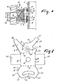
- annular support bracket 2 is welded to its stator tube 1 with its foot 3 pointing radially inwards.
- this annular support bracket 2 has a collar with two conical surfaces 4, 5 facing each other and a third conical lateral surface 6 in its lower part.
- This support bracket 2 is encompassed on its upper and lower surface by the two legs 7, 8 of a bow-shaped connecting member 10, on the rear end wall 9 of which a connecting pin in the form of a so-called tilting pin 11 is fastened, for example by welding.
- the flattened end 12 of a cross strut is pivotally attached to this pin 11 and secured against sliding out by the pin 13 articulated on the pin 11.
- the bracket-shaped connecting member 10 is held on the support bracket by a bolt 14, each with a head 15, 16 at its ends, which has an opening 17 in the upper leg 7, an opening 18 in the bracket 2 and an opening 19 in the lower leg 8 of the Intermediate link.
- This captive bolt 14 held in the connecting member 10 can be pulled out with its lower head 16 from the opening 19 and the opening 18 in order to be able to pull the connecting member 10 radially from the support bracket 2.
- His lower head 16 is in a bulge 20 in the region of the bore 17 in the upper leg 7 of the connecting member added so that it is sunk when removing the connecting member.
- the end wall 9 of the connecting member 10 can be adapted to the contour of the annular support bracket 2 in the circumferential direction as well as vertically, which results in a firmer fit. If, for example, the end wall 9 does not run in a straight line, as shown in FIG. 1, but rather its inner surface corresponds to the conical outer surfaces 5 and 6 of the support bracket 2, then when these surfaces are in mutual contact, the connecting member 10 is securely fixed to the support bracket 2 against upward and downward forces.
- This form-fitting fixation is further intensified by such a wedge-shaped design of the bolt 14 that the connecting member 10 is pulled against the two conical surfaces 5 and 6 with its two-faced rear end wall 9 when the bolt is driven in. This results in a tight fit, even if the two legs 7 and 8 of the connecting member 10 only loosely grip around the support bracket 2.
- the bow-shaped connecting member is shown as a sheet metal blank in plan view before bending to its U-shaped cross section shown in Fig. 1.
- the lower tab 8 has an arc-shaped end face 22, the radius of which is adapted to the curvature of the tube wall 1 and which is delimited laterally by two edges 23, 24 which run obliquely towards one another. Two arches 25, 26 and two inclined surfaces 27, 28 adjoin these surfaces.
- the Relatively wider flap forming the lower leg 8 merges with the dashed bend line 29 into the central part forming the rear wall 9 with parallel side lines 30, 31 and via the second bend line 32 into the flap forming the upper leg 7.
- the bore 17 and the bulge 20 are located approximately in the middle of this upper tab.
- This upper tab also has an arcuate end edge 35, the radius of which is adapted to that of the tube stand 1.
- This circular arc-shaped end edge is laterally delimited by two oblique edges 36, 37, of which the edge 36 delimits an incision 38 and the edge 37 delimits a tab 39.
- the other edge of the incision 38 delimits an oblique tab 40, the end 41 of which has a shape such that it fits into a recess 42 delimiting the tab 39.
- This recess 42 is delimited by a short side tab 43.
- the two side tongues 44, 45 shown can be formed, which are bent inwards around the side lines 30, 31 to such an extent that their free ends in the installed state on the support bracket 2 and on the side walls of adjacent connecting links 10 and / or of wedge hook connectors 51.
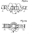
- 3a, 3b is a possibility for connecting two cross struts perpendicular to one another by means of two of the devices shown in FIGS. 1 and 2 gene shown in schematic side view and in plan view.
- Two crossbars 50a, 50b are fastened to the support bracket 2 welded to the pipe stand 1 by means of hook-wedge connectors 51a, 51b.
- the arcuate end edges 35a, 35b of the two connecting members 10a, 10b bear against the wall of the pipe stand 1.
- the tab 39a of the connecting member 10a engages in the cutout 38b of the connecting member 10b.
- the tab 40a is supported with its end face 41a on the radial side face of the hook-wedge connector 51a.
- the tab 40b of the connecting member 10b engages in the cutout 42a of the connecting member 10a. Finally, the end face 37b is supported on a radial side face of the hook-wedge connector 51b.
- the mutual interlocking of the two connecting links 10a and 10b and their respective abutment on the tubular stand 1 and on the crossbar connectors 51a, 51b achieve a secure positional fixation without a strong clamping effect between the connecting links 10 and the support bracket 2 being necessary .
- Fig. 4a, 4b differs from that according to Fig. 3a, 3b only in that the two crossbars 50a, 50b are connected diametrically opposite to the support bracket 2 and that only a single device 10 is present, which by the System of the radial inner surface 35 and the end surfaces 37, 41 of the two tabs 39, 40 supported laterally on each connector and thus ge against horizontal movements in the circumferential direction is secured.
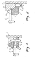
- radial bores 60 are machined into the support bracket 2 at predetermined angular intervals, into which a connecting bolt 61 can be inserted radially from the outside.
- This connecting bolt 61 has an outer end part which corresponds to the bolt 11 of the embodiment according to FIG. 1, i. H. forms a tilt pin.
- a stop z. B. in the form of a flange 62 is permanently attached to the bolt shaft and determines the position of the connecting bolt 61 in the inserted and fixed state.
- the front end of the bolt shank 63 has an opening 64 which serves to receive a wedge 65 which, when driven into a vertical recess 66 in the base of the ring console 2, pulls the bolt with the stop 62 firmly against the outer end face of the ring console.
- radial grooves 70 are incorporated in the collar of the ring bracket offset from each other, which each serve to receive a connecting bolt 71
- the front end z. B. can be designed as a tilt pin - corresponding to the tilt pin 11 of FIG. 1.
- This connecting bolt 71 is rigidly attached to a link 72, the cross section of which is designed such that it fits exactly into the space delimited by the tube wall 1 and the radially inner conical surface 4 of the support bracket 2.
- this link 72 has at least one - expediently two - pins or lugs 73 which reach through corresponding bores or recesses 74 in the annular base of the support bracket and with their ends z. B.
- the link 72 has a circular segment shape in plan view, so that it occupies a certain arc of the space between the tube stand 1 and the collar of the support bracket 2 and rests with its end faces on the side faces of connectors 50 or adjacent links 72.
- the engagement of the pins 73 in the bores 74 in the console foot, which are arranged at an angle to one another, provides effective protection against rotation with respect to horizontal and oblique forces acting in the circumferential direction.
- the invention is not limited to the embodiments shown. Rather, other design variants are possible.
- the radial bores 60 shown in FIG. 5 can have an internal thread, into which the connecting bolts 61 provided with a threaded shaft are then screwed.
- the stop 62 in the embodiment according to FIG. 5 can be adapted to the shape of the two conical surfaces 5, 6 of the support bracket 2, as a result of which a better positive locking is achieved.
Landscapes
- Engineering & Computer Science (AREA)
- Architecture (AREA)
- Mechanical Engineering (AREA)
- Civil Engineering (AREA)
- Structural Engineering (AREA)
- Gyroscopes (AREA)
- Mutual Connection Of Rods And Tubes (AREA)
Priority Applications (2)
| Application Number | Priority Date | Filing Date | Title |
|---|---|---|---|
| EP84100078A EP0147496A1 (fr) | 1984-01-05 | 1984-01-05 | Dispositif pour assembler des contrefiches aux montants d'un échafaudage modulaire |
| NO842242A NO842242L (no) | 1984-01-05 | 1984-06-05 | Anordning ved stillas |
Applications Claiming Priority (1)
| Application Number | Priority Date | Filing Date | Title |
|---|---|---|---|
| EP84100078A EP0147496A1 (fr) | 1984-01-05 | 1984-01-05 | Dispositif pour assembler des contrefiches aux montants d'un échafaudage modulaire |
Publications (1)
| Publication Number | Publication Date |
|---|---|
| EP0147496A1 true EP0147496A1 (fr) | 1985-07-10 |
Family
ID=8191682
Family Applications (1)
| Application Number | Title | Priority Date | Filing Date |
|---|---|---|---|
| EP84100078A Withdrawn EP0147496A1 (fr) | 1984-01-05 | 1984-01-05 | Dispositif pour assembler des contrefiches aux montants d'un échafaudage modulaire |
Country Status (2)
| Country | Link |
|---|---|
| EP (1) | EP0147496A1 (fr) |
| NO (1) | NO842242L (fr) |
Cited By (2)
| Publication number | Priority date | Publication date | Assignee | Title |
|---|---|---|---|---|
| US7975803B2 (en) * | 2001-06-15 | 2011-07-12 | Peri Gmbh | Dismantlable scaffold and a railing adapter for it |
| US20130319797A1 (en) * | 2012-06-01 | 2013-12-05 | Yu Shing SO | Scaffolding |
Citations (4)
| Publication number | Priority date | Publication date | Assignee | Title |
|---|---|---|---|---|
| DE2822676A1 (de) * | 1978-05-24 | 1979-11-29 | Eberhard Layher | Rohrgeruestsystem, insbesondere fuer baugerueste |
| EP0053970A1 (fr) * | 1980-12-04 | 1982-06-16 | Marcel Henri René Roux | Dispositif d'assemblage directionnel entre les éléments, notamment tubulaires, d'un échafaudage |
| DE8211065U1 (de) * | 1982-04-19 | 1982-10-07 | Flashlok Interscaffold AG, 63100 Zug | Bausatz fuer ein schnellbaugeruest |
| GB2097507A (en) * | 1981-04-29 | 1982-11-03 | Layher Eberhard | Scaffold member |
-
1984
- 1984-01-05 EP EP84100078A patent/EP0147496A1/fr not_active Withdrawn
- 1984-06-05 NO NO842242A patent/NO842242L/no unknown
Patent Citations (4)
| Publication number | Priority date | Publication date | Assignee | Title |
|---|---|---|---|---|
| DE2822676A1 (de) * | 1978-05-24 | 1979-11-29 | Eberhard Layher | Rohrgeruestsystem, insbesondere fuer baugerueste |
| EP0053970A1 (fr) * | 1980-12-04 | 1982-06-16 | Marcel Henri René Roux | Dispositif d'assemblage directionnel entre les éléments, notamment tubulaires, d'un échafaudage |
| GB2097507A (en) * | 1981-04-29 | 1982-11-03 | Layher Eberhard | Scaffold member |
| DE8211065U1 (de) * | 1982-04-19 | 1982-10-07 | Flashlok Interscaffold AG, 63100 Zug | Bausatz fuer ein schnellbaugeruest |
Cited By (4)
| Publication number | Priority date | Publication date | Assignee | Title |
|---|---|---|---|---|
| US7975803B2 (en) * | 2001-06-15 | 2011-07-12 | Peri Gmbh | Dismantlable scaffold and a railing adapter for it |
| US20130319797A1 (en) * | 2012-06-01 | 2013-12-05 | Yu Shing SO | Scaffolding |
| US10125505B2 (en) * | 2012-06-01 | 2018-11-13 | Wls Intellectual Property Limited | Scaffolding |
| US20190048600A1 (en) * | 2012-06-01 | 2019-02-14 | Wls Intellectual Property Limited | Scaffolding |
Also Published As
| Publication number | Publication date |
|---|---|
| NO842242L (no) | 1985-07-08 |
Similar Documents
| Publication | Publication Date | Title |
|---|---|---|
| DE60307910T2 (de) | Abstandshalter für Wirbelkörper | |
| DE2554855C3 (de) | Kupplungsstück für Baugerüste | |
| DE3147081A1 (de) | "geruest fuer betonschalungen" | |
| EP3464753A1 (fr) | Module de support vertical pour tour d'échafaudage pour charges lourdes | |
| CH656438A5 (de) | Einrichtung zur bildung eines geruests. | |
| EP3768915B1 (fr) | Cadre de support | |
| EP3538745B1 (fr) | Procédé de montage et/ou de démontage de composants d'une turbine comportant un carter de turbine, adaptateur et système à utiliser dans le procédé | |
| DE2557640A1 (de) | Befestigung fuer ein arbeitsgeruest, insbesondere an schiffen | |
| CH643401A5 (de) | Schutzleiter-reihenklemme. | |
| EP0147496A1 (fr) | Dispositif pour assembler des contrefiches aux montants d'un échafaudage modulaire | |
| EP0009680B1 (fr) | Echafaudage en tube d'acier | |
| DE2311199C2 (de) | Vorrichtung zum Verriegeln von Plattformen an Gerüstteilen | |
| EP1870534A2 (fr) | Structure de raidissement, élément de fixation et procédé destiné au raidissement du cadre de support d'un coffrage de plafond | |
| DE19703558B4 (de) | Stabeinrichtung für ein Gerüstsystem | |
| EP0622504B1 (fr) | Noeud et raccord de noeud pour système d'échafaudage | |
| AT396278B (de) | Stuetzvorrichtung | |
| DE60101513T2 (de) | Montierhilfe für Raupenkette | |
| EP0443111B1 (fr) | Connecteur pour la connexion d'une colonne avec une barre tubulaire, colonne connectée et ensemble avec au moins une colonne et une barre | |
| EP0317695B1 (fr) | Echafaudage métallique pour le bâtiment | |
| DE3222811C1 (de) | Verbindungsvorrichtung fuer zerlegbare Fachwerksbauten | |
| DE2920782A1 (de) | Kupplungsvorrichtung fuer stab- oder fachwerk-konstruktionen | |
| CH657656A5 (de) | Tragprofil zur abstandsbefestigung von fassadenverkleidungselementen an bauwerksteilen. | |
| DE20318433U1 (de) | Geländereinrichtung für den zeitweiligen Seitenschutz eines Baugerüstes | |
| DE3143951A1 (de) | "kombinierte dreh- und verschiebesicherung fuer einen bolzen" | |
| WO2007045300A1 (fr) | Systeme de bancs d'etirage pour machine textile |
Legal Events
| Date | Code | Title | Description |
|---|---|---|---|
| PUAI | Public reference made under article 153(3) epc to a published international application that has entered the european phase |
Free format text: ORIGINAL CODE: 0009012 |
|
| AK | Designated contracting states |
Designated state(s): BE DE FR GB IT NL SE |
|
| 17P | Request for examination filed |
Effective date: 19850722 |
|
| STAA | Information on the status of an ep patent application or granted ep patent |
Free format text: STATUS: THE APPLICATION HAS BEEN WITHDRAWN |
|
| 18W | Application withdrawn |
Withdrawal date: 19870819 |