EP0147032B1 - Manipulation de particules - Google Patents
Manipulation de particules Download PDFInfo
- Publication number
- EP0147032B1 EP0147032B1 EP84307496A EP84307496A EP0147032B1 EP 0147032 B1 EP0147032 B1 EP 0147032B1 EP 84307496 A EP84307496 A EP 84307496A EP 84307496 A EP84307496 A EP 84307496A EP 0147032 B1 EP0147032 B1 EP 0147032B1
- Authority
- EP
- European Patent Office
- Prior art keywords
- standing wave
- liquid
- particles
- column
- particle
- Prior art date
- Legal status (The legal status is an assumption and is not a legal conclusion. Google has not performed a legal analysis and makes no representation as to the accuracy of the status listed.)
- Expired - Lifetime
Links
Images


Classifications
-
- B—PERFORMING OPERATIONS; TRANSPORTING
- B01—PHYSICAL OR CHEMICAL PROCESSES OR APPARATUS IN GENERAL
- B01D—SEPARATION
- B01D21/00—Separation of suspended solid particles from liquids by sedimentation
- B01D21/28—Mechanical auxiliary equipment for acceleration of sedimentation, e.g. by vibrators or the like
- B01D21/283—Settling tanks provided with vibrators
-
- A—HUMAN NECESSITIES
- A61—MEDICAL OR VETERINARY SCIENCE; HYGIENE
- A61M—DEVICES FOR INTRODUCING MEDIA INTO, OR ONTO, THE BODY; DEVICES FOR TRANSDUCING BODY MEDIA OR FOR TAKING MEDIA FROM THE BODY; DEVICES FOR PRODUCING OR ENDING SLEEP OR STUPOR
- A61M1/00—Suction or pumping devices for medical purposes; Devices for carrying-off, for treatment of, or for carrying-over, body-liquids; Drainage systems
- A61M1/36—Other treatment of blood in a by-pass of the natural circulatory system, e.g. temperature adaptation, irradiation ; Extra-corporeal blood circuits
-
- B—PERFORMING OPERATIONS; TRANSPORTING
- B01—PHYSICAL OR CHEMICAL PROCESSES OR APPARATUS IN GENERAL
- B01D—SEPARATION
- B01D15/00—Separating processes involving the treatment of liquids with solid sorbents; Apparatus therefor
- B01D15/08—Selective adsorption, e.g. chromatography
- B01D15/26—Selective adsorption, e.g. chromatography characterised by the separation mechanism
- B01D15/38—Selective adsorption, e.g. chromatography characterised by the separation mechanism involving specific interaction not covered by one or more of groups B01D15/265 - B01D15/36
- B01D15/3861—Selective adsorption, e.g. chromatography characterised by the separation mechanism involving specific interaction not covered by one or more of groups B01D15/265 - B01D15/36 using an external stimulus
- B01D15/3866—Selective adsorption, e.g. chromatography characterised by the separation mechanism involving specific interaction not covered by one or more of groups B01D15/265 - B01D15/36 using an external stimulus using ultra-sound
-
- B—PERFORMING OPERATIONS; TRANSPORTING
- B01—PHYSICAL OR CHEMICAL PROCESSES OR APPARATUS IN GENERAL
- B01D—SEPARATION
- B01D43/00—Separating particles from liquids, or liquids from solids, otherwise than by sedimentation or filtration
-
- B—PERFORMING OPERATIONS; TRANSPORTING
- B03—SEPARATION OF SOLID MATERIALS USING LIQUIDS OR USING PNEUMATIC TABLES OR JIGS; MAGNETIC OR ELECTROSTATIC SEPARATION OF SOLID MATERIALS FROM SOLID MATERIALS OR FLUIDS; SEPARATION BY HIGH-VOLTAGE ELECTRIC FIELDS
- B03B—SEPARATING SOLID MATERIALS USING LIQUIDS OR USING PNEUMATIC TABLES OR JIGS
- B03B1/00—Conditioning for facilitating separation by altering physical properties of the matter to be treated
-
- C—CHEMISTRY; METALLURGY
- C12—BIOCHEMISTRY; BEER; SPIRITS; WINE; VINEGAR; MICROBIOLOGY; ENZYMOLOGY; MUTATION OR GENETIC ENGINEERING
- C12M—APPARATUS FOR ENZYMOLOGY OR MICROBIOLOGY; APPARATUS FOR CULTURING MICROORGANISMS FOR PRODUCING BIOMASS, FOR GROWING CELLS OR FOR OBTAINING FERMENTATION OR METABOLIC PRODUCTS, i.e. BIOREACTORS OR FERMENTERS
- C12M47/00—Means for after-treatment of the produced biomass or of the fermentation or metabolic products, e.g. storage of biomass
- C12M47/02—Separating microorganisms from the culture medium; Concentration of biomass
-
- C—CHEMISTRY; METALLURGY
- C12—BIOCHEMISTRY; BEER; SPIRITS; WINE; VINEGAR; MICROBIOLOGY; ENZYMOLOGY; MUTATION OR GENETIC ENGINEERING
- C12N—MICROORGANISMS OR ENZYMES; COMPOSITIONS THEREOF; PROPAGATING, PRESERVING, OR MAINTAINING MICROORGANISMS; MUTATION OR GENETIC ENGINEERING; CULTURE MEDIA
- C12N13/00—Treatment of microorganisms or enzymes with electrical or wave energy, e.g. magnetism, sonic waves
-
- C—CHEMISTRY; METALLURGY
- C12—BIOCHEMISTRY; BEER; SPIRITS; WINE; VINEGAR; MICROBIOLOGY; ENZYMOLOGY; MUTATION OR GENETIC ENGINEERING
- C12Q—MEASURING OR TESTING PROCESSES INVOLVING ENZYMES, NUCLEIC ACIDS OR MICROORGANISMS; COMPOSITIONS OR TEST PAPERS THEREFOR; PROCESSES OF PREPARING SUCH COMPOSITIONS; CONDITION-RESPONSIVE CONTROL IN MICROBIOLOGICAL OR ENZYMOLOGICAL PROCESSES
- C12Q1/00—Measuring or testing processes involving enzymes, nucleic acids or microorganisms; Compositions therefor; Processes of preparing such compositions
- C12Q1/02—Measuring or testing processes involving enzymes, nucleic acids or microorganisms; Compositions therefor; Processes of preparing such compositions involving viable microorganisms
- C12Q1/24—Methods of sampling, or inoculating or spreading a sample; Methods of physically isolating an intact microorganisms
-
- G—PHYSICS
- G01—MEASURING; TESTING
- G01N—INVESTIGATING OR ANALYSING MATERIALS BY DETERMINING THEIR CHEMICAL OR PHYSICAL PROPERTIES
- G01N15/00—Investigating characteristics of particles; Investigating permeability, pore-volume, or surface-area of porous materials
- G01N15/02—Investigating particle size or size distribution
-
- B—PERFORMING OPERATIONS; TRANSPORTING
- B01—PHYSICAL OR CHEMICAL PROCESSES OR APPARATUS IN GENERAL
- B01D—SEPARATION
- B01D21/00—Separation of suspended solid particles from liquids by sedimentation
- B01D21/0087—Settling tanks provided with means for ensuring a special flow pattern, e.g. even inflow or outflow
-
- G—PHYSICS
- G01—MEASURING; TESTING
- G01N—INVESTIGATING OR ANALYSING MATERIALS BY DETERMINING THEIR CHEMICAL OR PHYSICAL PROPERTIES
- G01N30/00—Investigating or analysing materials by separation into components using adsorption, absorption or similar phenomena or using ion-exchange, e.g. chromatography or field flow fractionation
- G01N30/02—Column chromatography
- G01N2030/022—Column chromatography characterised by the kind of separation mechanism
- G01N2030/027—Liquid chromatography
-
- G—PHYSICS
- G01—MEASURING; TESTING
- G01N—INVESTIGATING OR ANALYSING MATERIALS BY DETERMINING THEIR CHEMICAL OR PHYSICAL PROPERTIES
- G01N30/00—Investigating or analysing materials by separation into components using adsorption, absorption or similar phenomena or using ion-exchange, e.g. chromatography or field flow fractionation
- G01N30/02—Column chromatography
Definitions
- the present invention relates to the manipulation of particulate matter in a fluid medium by the use of ultrasonic wave energy, and in particular for the separation of particles, including the segregation of dissimilar particles from a mixture of particles in a fluid, whether for example for concentrating particular types of particle or for finely separating or "chromatographing" particulate matter.
- the transducer is positioned at one end of a hollow gas-filled tube and is reflected back from the opposite end.
- the interference between the incident and reflected waveforms produce a standing wave that is said to function as the plates of a conventional chromatographic column, as is known for molecular separation, by retaining different size molecular particles at the nodes of the wave pattern for different times.
- the standing wave pattern is generated in a vertical gas column into which a sample of body fluid components, such as blood cells or bacteria, are injected to be transported by the combined effects of gravity and the carrier gas flow through the column and past a detector for detecting the passage of constituents of the sample which have undergone some degree of separation by the standing wave pattern.
- the standing wave is produced by tuning the generator driving the transducer to a resonant frequency of the column length so that interference between the emission from the transducer and the reflection from the opposite end of the column produces a stationary pattern of nodes and antinodes.
- Such an arrangement is subject to many practical limitations, such as the difficulty of injecting a particulate sample into a gas stream, the difficulty of controlling the separation rate in the carrier gas flow while maintaining the particles suspended therein, and the practical impossibility of achieving a measurable separation between sample components that act very similarly to external forces, such as gravity, upon them.
- US 4280823 suggests that the wave frequency can be changed to control the resolution of the column, (i.e. altering the distance between nodes or "plates") and if the wavelength is small in relation to the column length there would be a number of discrete resonant frequencies. It is also suggested that a non-resonant mode can be employed, although with a loss of efficiency, but unless there is resonance the transducer emission will then be unable to produce a standing wave pattern. Control of the separation of the constituents of a sample is thus limited in practice to varying the carrier gas speed and/or the wave intensity, both of which can introduce undesirable secondary effects. Any control of selectivity by change of frequency must be limited to a relatively small number of discrete steps if the standing wave pattern is to be maintained.
- the particles are also subjected to an external force, in particular gravity, acting transversely to the flow and there is some separation within the well depending upon the reactions of particular particle types to the acoustic energy force and the additional transverse force, so that the different particle types tend to settle at different heights within the force-potential well, or if the influence of the transverse force is sufficiently strong they fall to the bottom of the chamber because the acoustic energy force falls off rapidly once the particle has fallen more than half way between the centre of the well (a node) and the antinode below.
- an external force in particular gravity, acting transversely to the flow and there is some separation within the well depending upon the reactions of particular particle types to the acoustic energy force and the additional transverse force, so that the different particle types tend to settle at different heights within the force-potential well, or if the influence of the transverse force is sufficiently strong they fall to the bottom of the chamber because the acoustic energy force falls off rapidly once the particle has fallen more than half way between the centre of the well
- GB 2098498A in which there is described a method of displacing contaminating particles in a flow of lubricant through a pipe to bring them towards a magnetic collector, by the use of two opposed ultrasonic sources that generate a standing wave with its axis running transversely across the pipe.
- the ultrasonic sources are so controlled in phase that the standing wave drifts across the flow.
- Metallic particles carried in the flow are thereby deflected towards one side of the pipe as they pass through the standing wave to bring them under the influence of the magnetic collector in an offset collection zone at that side of the pipe.
- the collector then retains the particles and can be removed and cleaned from time to time.
- apparatus for separating one or more particle types present in particulate matter comprising a liquid-filled space and fluid inlet and outlet means for admitting the liquid and matter into and removing them from said space, spaced ultrasonic energy sources directing respective outputs into the liquid-filled space to generate by interference between their outputs a standing wave in the space occupied by said liquid and the particulate matter, wherein the liquid-filled space is in the form of a column with the axis of the standing wave directed longitudinally of the column and the inlet and outlet means spaced therealong, and for the separation of the or each specific particle type there being provided means for varying the frequency of the ultrasonic energy sources, and/or means for controlling the amplitudes of the outputs of the two sources so as to vary the intensity of the standing wave, and/or means for controlling the relative phase of the two outputs so as to hold the standing wave fixed or to produce an adjustable rate of drift of said standing wave along the liquid-filled space, and/or means for producing a controll
- the standing wave pattern results from the superimposition of the progressive wave outputs of the two sources, the standing wave occurring in the area of overlap of the two progressive wave patterns whether or not the axes of propagation of the outputs from the two sources are coincident. If the two opposing progressive waves differ in amplitude the net effect is a standing wave upon which is superimposed a progressive element. In practice this will almost always arise to some degree due to the attenuation of the waves in the fluid medium (although at frequencies up to the order of 10 2 MHz it is possible to balance the amplitudes to produce operating zone of useful length in which progressive wave components are negligibly small and in some special cases higher frequencies may be applicable). If the two progressive waves differ slightly in frequency, the standing wave will drift towards the source emitting the lower frequency. If the two opposing waves differ both in frequency and in amplitude a combination of these effects will be observed, and by means of the control of the sources each effect can be regulated to achieve the desired result.
- the invention utilises a phenomenon which we shall term herein as "nodal delay".
- a particle suspended in a liquid and located in a drifting standing wave will move with the nodes of the standing wave if the acoustic forces predominate, whereas if subject to Stokes force due to movement of the liquid and these viscous drag forces predominate it will move with a mean velocity equal to the liquid velocity. If the peak acoustic forces are almost exactly balanced by the non-acoustic forces, the particle will move at times with the same velocity as the nodes, and at other times will move with a complex oscillating motion in which, however, the standing wave does not impart any net motion to the particle.
- the acoustic energy density of each part of a nodal array will not be exactly equal, nor may it be possible to have non-acoustic forces with a constant magnitude in every part of a system.
- the particle may be subject to Brownian motion which at one moment may augment the acoustic forces and at another moment may augment the non-acoustic forces. For such reasons, when the opposing forces are nearly in balance, a given particle will at one moment move with the standing wave but at another moment will not move with the wave.
- the "nodal delay" is the sum of all those times during which the given particle is not moving with the wave. Thus, if the tendency of a given particule type to mass at the nodes overrides totally the effect of the opposing forces in the fluid medium, the nodal delay then experienced by that particle type is zero. If the tendency of a given particle type to remain at the nodes is overriden totally by the effect of the opposing forces, the nodal delay experienced by that particle type can be said to be infinite. Nodal delays having intermediate values arise only when the acoustic and the non-acoustic forces are nearly in balance.
- nodes are used herein to include both nodes and antinodes, because in practice it does not appear to matter to the results that can be achieved.
- the acoustic forces acting on a particle that is small compared to the wavelength of a stationary standing wave having no progressive element, if these forces predominate they urge the particle to the nearest node (in this explanation, those stations along the axis or propagation which the adjacent net acoustic forces act towards are termed nodes and those which said acoustic forces act away from are termed antinodes).
- nodes those stations along the axis or propagation which the adjacent net acoustic forces act towards
- antinodes those stations along the axis or propagation which the adjacent net acoustic forces act away from are termed antinodes.
- the particle moves to the node at a velocity proportional to the magnitude of the net acoustic force on it at any instant-i.e. the particle reaches a maximum velocity when at an intermediate point between a node and an adjacent antinode.
- the position of the standing wave is fixed (i.e. the array of nodes forming the standing wave is at least substantially motionless relative to the sources generating the standing wave) and the carrier liquid flows through the standing wave.
- the nodes of the standing wave can be likened to a series of filters or grids through which the particles in the liquid have to pass as they are carried along by the stream.
- the nodes of the standing wave can be likened to a comb that is passed through the liquid medium and tends to sweep particles with it. It will be understood that by combination of the movements of both the liquid and the standing wave, as well as by controlling the standing wave intensity and/or frequency, it is readily possible to achieve an extremely wide degree of control.
- the present invention also comprises an arrangement in which there is a component of fluid flow normal to the axis of the standing wave, in an extreme case the fluid flow being substantially at right angles to the standing wave axis. It is therefore necessary to consider also the effect of forces acting normal to the axis of the standing wave.
- a particle influenced by the standing wave will not only move towards a node but because the acoustic energy density in the nodal plane will generally not be uniform, it will move parallel to the plane in the direction of increasing energy density.
- the energy density gradient in the plane of the node is very much smaller than the gradient axially of the standing wave, especially at the ultrasonic frequencies used in the present invention. It can thus be displaced parallel to the nodal plane by a much smaller non-acoustic force.
- the work done to remove the particle axially from a node to an adjacent antinode is however the same as removing it parallel to the nodal plane, the displacement required parallel to the nodal plane being much greater than the displacement from a node to an adjacent antinode. It is therefore easier to detach a particle from a standing wave by a liquid flow normal to the axis of the wave than by an axial flow relative to the standing wave.
- the velocity with which a particle moves in the plane of a node is not always the same as the liquid flow velocity in this direction; the particle will accelerate as it moves up an acoustic energy density gradient and will slow in a decreasing gradient.
- the average velocity is that of the velocity of the carrier liquid in the plane of the node, unless the particle is held by the node at some local high acoustic energy density region from which the Stokes forces cannot dislodge it for a time. Finite nodal delays therefore can operate in directions both analog and transverse to the axis of the standing wave.
- the nodal delay experienced in this transverse flow case will be a composite of the transverse nodal delay and the previously described axial nodal delay.
- the invention may be used for the analysis and separation of a very wide size range of particles.
- suitable biological particles there can be considered animal cells, for instance mammalian cells.
- red blood cells (7 microns) which have a density of 1.09 gm/cc and are disc shaped
- reticulocytes which are immature red cells (5 microns) and have a distinctive internal structure and acoustic character
- other blood particulates such as neutrophils (10 microns), monocytes (14-20 microns) and lymphocytes (10 microns).
- suitable biological particles for treatment are plant cells (typically 20-30 microns), microorganisms (a typical coccus being about 1-2 microns in diameter while a bacillus is rod-shaped about 2-3 microns long), and spores of microorganisms which are much denser (specific gravity 1.3) than when in the vegitative state.
- Cell constituents such as nuclei, mitachondria and microsomes are further examples of biological particles that can be treated using the method of the present invention, and as further instances may be mentioned plankton, yeasts, pollen, protozoa, richetsia and viruses.
- the method of the invention can be employed for the manipulation of many industrial particulates, including dispersions, suspensions and finely-divided precipitates.
- clays the plate-like hydrous aluminium silicate particles which range in size from colloidal to 4 microns
- cement the particles of Portland cement are ground to sizes mostly below 10 microns
- paint pigments titanium dioxide may be used in particles about 0.3 microns in diameter
- dusts such as coal dusts and asbestos.
- the upper size limit for manipulation of particles by the method of the invention is determined by the internodal distance in the standing wave. Acoustic forces on the particles essentially cease to be effective when the particle is so large that it spans the distance between a node and the adjacent antinode. In water at NTP, with directly opposed ultrasonic sources at 100 kHz, this distance is about 3.5 mm.
- the lower limit to size is more difficult to specify because of the number of factors involved and requires to be determined experimentally in any particular case. It appears that one factor is the size of particles relative to the internodal distance, between the efficiency of separation falls as the difference between these dimensions increases.
- the optimum frequency needed to establish an appropriate standing wave in water will be in the range 100 kHz to as high as 250 MHz, or more usually 100 MHz. In the upper end of this range it is necessary to consider the reduction of intensity of the ultrasonic radiation with distance from the source: such attenuation means that the two progressive waves cannot be identical in amplitude except in a very small region and in practice the standing wave will include a minor progressive component.
- liquid e.g.
- the use of water has an advantage in that it is a benign medium for biological particles generally.
- At higher frequencies there are also the advantages of a reduction of beam spread and the ability to use higher powers without risk of cavitation. It has been found, moreover, that the efficiency of association of particles with nodes increases with frequency.
- water is the most appropriate medium it may be advantageous to increase the density of the liquid by the addition of solutes such as sucrose, or to control osmotic effects, or to increase viscosity by the addition of suitable macromolecular materials.
- Polar liquids having a lower density than water such as methyl alcohol, may be useful carrier liquids for some particulate materials, while for the analysis of substances sensitive to polar liquids, such as cereal flours, or for water-sensitive powders such as cements, non-polar liquids such as kerosene would be chosen.
- oils having a higher viscosity and lower density than water. It will be understood that the different characteristics of such diverse liquids will be a factor in determining the frequencies of the ultrasonic sources employed.
- the invention may be embodied in applications in which the carrier liquid has a higher density than the particulate material.
- a high density mobile liquid such as bromoform may be suitable to some particular cases.
- the method of the present invention can be operated at temperatures both considerably higher and lower than room temperature, and the static pressure may also be controlled, so that substances normally solid or gaseous at normal temperatures and pressures can also be considered as carrier liquids.
- inorganic particles it may be preferred to use liquid carriers other than water, e.g. for density considerations or in order to ensure that the particulate material is dispersed.
- the net free energy of the system is reduced as the particles collect at the nodes.
- the degree to which the net free energy of the system is reduced as a particle moves to a node, and conversely the work which needs to be done in order to remove the particle from the node depends on the acoustic properties of the particle, that is, its shape, size, density, compressibility, rigidity and general physical internal structure, the properties of the fluid, e.g. its density and the speed of sound in the fluid, and the intensity and frequency of the ultrasonic standing wave.
- the tendency of the wave to accumulate particles at its nodes can be opposed by a wide variety of means in order to counterbalance, wholly or partially, the forces exerted on the particles due to the standing wave, so creating a situation in which motion of the particles can be controlled.
- Relative motion between the fluid medium supporting the particles and the standing wave as already described provides an important means .of control, but in general the controlling influences may include further external forces, e.g. electromagnetic or electrostatic or centrifugal or gravitational force fields, and these can be controllably combined to determine the rate and degree of separation.
- red blood cells carry a charge and in an electric field they therefore have acting on them a force proportional to the product of the charge and the electric field strength. This force could be used to oppose the acoustic forces holding a red blood cell in a standing wave.
- Variation of the energy intensity of the standing wave and/or its frequency provides further means of control.
- the apparatus comprises a vertical column 100 formed from a glass tube 101 having a bore 2.5 mm diameter and an external diameter of 7 mm fitted with access ports, 102, 103, 104, 105 and 106.
- These ports comprise small stainless steel tubes having a bore of 1 mm diameter and having ends flush with the internal bore of tune 101.
- Each port has a 0.5 mm bore silicone rubber connecting tube provided with a pinch valve 107, 108, 109, 110 and 111 respectively.
- Gelatine plugs 112, 113 respectively are cast into the section of tube 101 between the bottom of port 102 and the base of the column 100 and between the top of the port 102 and the base of the column 100 and between the top of the port 105 and the top of the column 100.
- These plugs of 10% w/w gelative in water have been hardened with formaldehyde and form low attenuation acoustic windows having an ultrasonic impedance very similar to water.
- the lower end of column 100 dips into water contained in a vessel 114 in which there is a 10 mm diameter barium titanate piezoelectric transducer 115 having a resonant frequency of 2.02 MHz.
- the transducer 115 is mounted inside the vessel 114 on a horizontal base 116 with its centre in line with the vertical axis of the column 100 and with the transducer transmitting face normal to this axis.
- the upper end of the glass tube 101 projects into a vessel 117 and is in contact with water contained in the vessel.
- a second 10 mm diameter barium titanate transducer 118 having a resonant frequency of 2.02 MHz is positioned such that the centre line of transducer 118 coincides with the centre line of the glass tube 101, and the transmitting face of transducer 118 dips into the water in vessel 117 and is normal to the centre line of glass tube 101.
- Each transducer 115, 118 has an impedance of about 50.
- Means are provided (not shown) to set and maintain the alignment of transducers 115 and 118 coaxial one with the other and with their transmitting faces parallel. Means are also provided (not shown) for transverse and angular adjustment of the tube 101 to set the axis of the column 100 coincident with the common axis of the transducers 115 and 118.
- a peristaltic pump 119 is connected by 0.76 mm bore plastic tubes 120, 121 to port 102 via valve 107 and to a vessel 122. Similar small bore plastic tubing 123 connects the distal end of valve 108 to the contents of vessel 122. A miniature ultrasonic bath 124 contains vessel 122 and provides agitation to the contents of the vessel. A motorised syringe 125 is connected via the valve 109 to the port 104 with similar bore plastic tubing 126. The valve 110 connects the port 105 to a vessel 127, also via small bore plastic tubing 128. Similar tubing 129 connects the valve 111 to vessel 130 via a peristaltic pump 131.
- a power source 132 is connected to a phase shift control arrangement 133 whereby two electrical driving outputs are produced with a progressive change of phase between them, whereby the interaction of ultrasonic outputs from the opposed transducers in the column produce a standing wave pattern having a relative slow drift towards the lagging phase output.
- a Wavetek Model 186 Phase Lock Sweep Generator which is able to produce an output in predetermined phase relationship to a reference input voltage, in dependence upon the application of a dc bias voltage.
- the two transducers are driven, one by the reference voltage and the other by the phase-controlled output voltage.
- a microprocessor is programmed to produce a cyclic stepped output that controls the bias voltage, so that the phase difference between the reference voltage and the phase-controlled output voltage change in progressive steps to produce a series of momentary frequency differences that result in drifting of the standing wave.
- the rate of drift is determined of course by the magnitude and frequency of the changes of reference voltage as set by the microprocessor programme.
- Polystyrene divinyl microspheres having a density of about 1.05 grams per ml and a known size distribution were separated into fractions having different size distributions using the apparatus described above.
- Clean, particle-free water was placed in vessel 122 and pumped by pump 119 via valve 107 into the column 100 and out via port 105 to fill completely the space between the plugs 112, 113. Care was taken to ensure that no small bubbles remained in the column. Clean water was also expressed by the motorised syringe 125 via valve 109 to displace all air but thereafter the valve 109 was closed. When the column was completely filled with water, the water in vessel 122 was replaced by the segregation sample consisting of 10 ml of an aqueous suspension of 3.3x10 7 microspheres having a diameter of a few microns.
- the transducers 15, 118 and the glass tube 101 aligned as already described the transducers were energised at 55 volts and by the driving outputs, the voltage applied being adjusted to produce equal acoustic outputs from the transducers.
- a standing wave was thus formed throughout the bore of the glass tube 101.
- the phase shift control arrangement was so adjusted that the standing wave pattern progressed upwards at a velocity of 50 mm per minute.
- the apparatus was operated with valves 111 and 110 closed.
- the suspension of particles contained in vessel 122 gently agitated by the ultrasonic bath 123 was drawn by the pump 119 through valve 108 into port 103 to flow down the column and return to the vessel via port 102, valve 107 and tubing 120 at a rate of 0.77 ml per minute in the return to the vessel 122.
- the working length of the column between the ports 102, 103 is about 10 mm.
- the motorised syringe 125 was operated to drive water down the column via valve 109 and port 104 at a rate of 0.1 ml per minute, to join the flow of suspended particles in the tube 120 into vessel 122.
- a liquid flow was thus established having an average velocity of 20 mm per minute down the tube 101 between ports 104 and 103 and a velocity of 180 mm per minute between ports 103 and 102. Since the standing wave was moving up the column at 50 mm per minute, the mean relative velocity between the water and the standing wave was 70 mm per min between ports 104 and 103 and 230 mm per minute between ports 103 and 102.
- Polystyrene particles exceeding a specific minimum diameter were collected by the moving nodal array from the junction of the port 103 and carried to the top of the column to collect on the lower face of the upper gelatine acoustic window. The process was operated for 20 minutes when the circulation of the supply of particles to the column was stopped by stopping the pump 119 and the syringe 125. Valves 107 and 108 were closed, valve 111 was kept closed and valve 110 was opened.
- Table 1 shows the change in composition of the population of microspheres in vessel 122 at the beginning and the end of the run and the composition of the population collected in the vessel 127.
- Group A particles were fed to the drifting standing wave at a rate of 1.2 million per minute, and 55,000 of these lifted to the top of the column per minute, that is 4.5%.
- Group B particles were fed to the drifting standing wave through port 103 at a rate of 1.09 million per minute, and 150,000 of these were transported to the top of the column per minute, that is, 14%.
- the internodal distance of the standing wave in water is about 0.35 mm, so at a wave drift of 50 mm per minute, 143 nodes pass per minute. Since the total number of particles collected in vessel 127 was 4.35x10 6 collected in 20 minutes, 217,500 particles per minute were being transported up the column, that is an average of over 1,500 on each node.
- the process may be operated continuously, that is to say, with a continuous supply of fresh material to port 103, the port 105 remaining open to a small scavenging liquid flow that carries separated particles out of the column. It may also be noted that in a discontinuous mode of operation different groups of particles can be collected successively at the port 105, the apparatus being controlled in such a way that the different types of particles in a sample are retained in the column for different periods of time, e.g. by progressive changes of the intensity of the standing wave or of the relative velocity between the standing wave and the carrier liquid so that the nodal delay characteristic of each particle type determines the order in which the respective types reach the port 105.
- Polystyrene microspheres were separated into fractions having different size distributions as for Example 1 and using the apparatus hereinbefore described, but the concentration of particles initially in vessel 122 was only half that in Example 1.
- Fig. 2 shows a histogram of the percentage of the total number of particles falling into various size groups in a sample being taken from the vessel 122 at the start of the run, while
- Fig. 3 shows a similar histogram of the size distribution of particles taken from a vessel 127 at the end of the run.
- the mean diameter of particles in the vessel 122 at the start of the run was 7.04 p and that of the particles in the vessel 127 at the end of the run was 9.4 p.
- Fig. 1 Using the method of Example 1, the apparatus shown in Fig. 1 was used to test its ability to select quickly and concentrate a small fraction of larger particles about 9 microns in diameter present in a large proportion of smaller particles, about 2 microns in diameter.
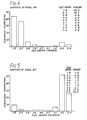
- the analysis of the size of distribution of the initial mixture of polystyrene microspheres placed in the vessel 122 is given as a histogram in Fig. 4, based on a count of 30,000 particles.
- Fig. 5 is a histogram to the same scale of the size distribution of the particles collected in the vessel 127 after 30 minutes.
- the ratio of these two size groups therefore changed from an initial 10 to 1 down to 0.9 to 1, that is, an overall change exceeding 50 to 1. This was achieved in a single pass through a 38 mm length of working column with ultrasonic standing wave patterns drifting at a rate of 50 mm per minute.
- Adjustment of the velocities of the standing wave and of the counter-flow in the column 101 result in the predicted results. For instance, in a further experiment, the percentage of the particles falling in the size group 14.3 microns increased when the wave drift velocity was increased, while those somewhat smaller decreased. The change in this size group with changing wave velocity at a constant acoustic energy and a constant counter flow is shown in Table 3.
- the apparatus of Fig. 1 can also be employed with circulation of liquid from the vessel 122 through the column from port 102 to port 103, i.e. in the same direction as the wave drift.
- the velocity of liquid flow then has the same direction and can be arranged to be not far different from the velocity of wave drift.
- the nodes of the wave pattern are loaded with particles experiencing little if any nodal delay and consequently there is no significant separation of the particles.
- the port 103 where the liquid flow exits, the particles reach a local zone in which the relative velocity between the liquid and the drifting wave increases, causing separation of the particles here, with a fraction of larger mean size being carried up the column by the standing wave, while the remainder of the particles return via port 103 to the tank 122.
- the vessel 127 is not needed nor is the connection from port 103 to the vessel 122.
- the pinch valve 108 is repositioned so that a short length of 0.5 mm bore silicone tubing connects the valve to the port 103, sufficient to allow the needle of a hypodermic syringe (not shown) to pierce the tubing wall and pass through the bore of port 103 to enter the bore of tube 101.
- this suspension of microorganisms was loaded into a 5 ml hypodermic syringe fitted with a long needle and the needle was passed through the wall of the tubing connected to the port 103, and through that port to inject 40 microlitres of the suspension into the base of the filled tube 101.
- This injected suspension of microorganisms occupied about an 8 mm length of the tube 101 adjacent to port 103. Whilst the sample was being loaded into the column, valves 107,108,109 and 111 were closed and valve 110 was opened to allow displaced peptone water to leave the column.
- valve 107 With valve 107 then opened, the transducers 115 and 118 were energised at 2 MHz and 50 volts and the resultant standing wave was held stationary or nearly so e.g. with a downwards drift of 1 mm per minute, while sterile 0.1% peptone water contained in vessel 122 was pumped through port 102 at an average velocity in the bore of the tube 101 of 4 mm per minute. After eight minutes, the carrier fluid emerging from the outlet tube connected to the valve 110 at a rate of one drop every two minutes was collected.
- each drop was separately collected in a sterile McCartney bottle containing 10 ml of sterile 0.1 % peptone water and the number of colony-forming units contained in each drop (0.4 ml) of carrier fluid emerging from the column was determined separately for each of the two microorganisms.
- the standing wave was extinguished and the contents of the tube 101 were flushed out.
- PCA Plate Count Agar
- PDA Potato Dextrose Agar
- the PDA plates incubated at 30°C for 3 to 4 days allowed colonies of yeast only to develop because the low pH of the medium suppressed all growth of the Serratia marcescens.
- the colonies which developed on the plates were counted after incubation at temperature and times given above. Any appropriate counting method can be used, but in this example the counts on the plates having large numbers of colonies were given greater statistical weight than the count of the next highest dilution.
- the viable counts of the yeasts and the bacterium in the mixed population as injected into the column were:
- Fig. 6 The number of Serratia marcescens and Torulopsis bombicola colony-forming units found in each drop of carrier fluid emerging from the outlet of the column via the port 105 is shown in Fig. 6 plotted against time. Note that the highest concentration Serratia marcescens appears as a peak 4 minutes before the highest concentration of Torulopsis bombicola was reached.
- the ratio of the bacteria to the yeast was always greater than the ratio (7.5:1) at which they were injected into the column and the maximum ratio reached was 80:1.
- the average ratio over the period during which the column was working was 24:1, nearly a three-fold enrichment.
- the total number of bacteria injected was 16.5x10⁶, while 11 x10 6 were recovered from the outlet of the column while the standing wave was maintained and a further 5x10 6 were recovered subsequently while the column was flushed out. Thus all the bacteria subjected to the ultrasonic wave were recovered as viable, colony forming units after one hour of exposure, within experimental error.
- the total number of yeast cells injected was 22 ⁇ 10 5 of which 5x10 5 were recovered from the outlet while the standing wave was maintained and 1 x 10 colony-forming units were recovered after the column was shut down and flushed out.
- the apparent loss is believed to have been due to the observed clumping of the yeast cells at the nodes of the standing wave, because these clumps were not completely broken down in the counting procedure and hence each colony-forming unit constituted a group of viable cells.
- the ratio of the concentrations of the two microorganisms at 10 minutes and after 50 minutes operation would have been different. No such difference was observed.
- the enrichment of the bacteria in the population emerging from the column was due to the greater nodal delay to which the somewhat larger yeast cells were subjected to as they passed through the standing wave.
- the process involves separation of a mixture of particles into two groups.
- the ports 102, 103 are used to provide a continuous supply of feedstock while the port 104 is employed to establish a liquid flow down the column.
- Port 105 is opened intermittently to remove the particles of one separated group, otherwise it and the port 106 remain closed.
- Example 4 a discontinuous process using the illustrated apparatus was performed in which particle size groups were separated by bringing them to the port 105 spaced in time, and in principle such temporal separation can be employed if more than two groups are to be differentiated. In this case only the ports 102 and 105 are open continuously, the port 103 being used simply for initial injection of the sample.
- the apparatus can also be operated to provide further degrees of separation in a continuous process by control of the velocities of the liquid flow and the standing wave, and by opening valve 111 to permit a flow through port 106, which has not been employed in any of the examples so far described.
- the flow through the port 104 is established such that the, liquid flows from port 104 to port 106 with a velocity less than the flow velocity between ports 103 and 102. Because liquid is drawn off at the port 106, the flow velocity from port 106 to port 103 is lower still.
- apparatus may comprise further liquid inlet and/or outlet ports along the length of the column to establish a series of different flow velocity regimes, thereby to increase the number of fractions into which a mixed group of particles is separated in a continuous process.
- Separation of different groups of particles that are differently influenced by the standing wave can also be obtained by controlling the intensity of the standing wave.
- a mixed sample of particles is injected into a flow of fluid in a column in which a standing wave pattern is established, as already described, it is possible to select an initial acoustic energy level at which all but a first group of weakly influenced particles are retained at the nodes. This first group is carried along in the liquid flow and can be collected separately from the remainder of the particles. The energy level of the standing wave is then decreased to allow a further fraction of the particles to be released and collected, and the process can be repeated to collect further fractions. It will be clear that it is also possible to control separation by a combined variation of the standing wave intensity and the relative movement between the carrier fluid and the standing wave pattern.
- a chamber 202 fabricated from polymethylmethacrylate with front and back plates 204, 206 each 6 mm thick defining between them a working column 2083 3 mm deep extending between parallel side walls 210.
- the working length between the inlet and the end sections is 24 mm.
- an inlet tube 218 is an inlet tube 218 through which a mixture of particles to be separated is introduced into the chamber.
- the chamber is mounted vertically with the outlets uppermost in a larger container (not shown) where it is immersed in a carrier fluid (Isoton II-Coulter Electronics Limited) which fills the container and provides acoustic coupling for two ceramic (barium titanate) transducers 220, 20 mm highx10 mm deep, operating at a frequency of 4.36 MHz.
- the transducers are mounted about 260 mm apart facing each other and are both coaxial with the centre line of 20 mm high acoustic windows 222 in the opposite side walls 210 of the chamber.
- the windows have a thickness equal to an integral number of half wavelengths of the outputs from the transducers, thus maximising acoustic transmissions into the working column 208.
- Other parts of the chamber walls have thicknesses which are of numbers of quarter wavelengths in order to provide maximum sound reflection, thus shielding areas inside the cell from the standing wave.
- the outlet ports are connected by small bore tubing to a peristaltic multi-channel pump (Watson-Marlow 202U/AA10) (not shown) which draws carrier liquid uniformly from the larger container into the chamber 208 from where uniform flows are drawn through the outlet sections 214.
- a peristaltic multi-channel pump Watson-Marlow 202U/AA10
- the amplitudes of both transducers 222 are matched such that, in the absence of the chamber 202 the energy density at the centre of the larger container on the common axis of the transducers is 2.5 J/m 3 .
- a mixture of polystyrene and divinylbenzene microspheres having a concentration of about 2.1 0 7 ml was pumped through the inlet tube 218 at 0.0112 ml per minute while 0.148 ml per minute was pumped out of each of the six outlet tubes 216, giving a mean liquid flow velocity in the working volume of the chamber of 12.3 mm per minute.
- the standing wave was caused to drift, the movement being to the right as seen in Fig. 8 (i.e. away from the side wall at which the particles are fed into the chamber), at 24.2 mm per minute.
- composition of the particle population appearing at the outlet tubes is shown in Fig. 10 in a grouped histogram of percentage composition in each of seven size groups (2.5 to 12.7 microns) for each port. Table 4 below also shows the percentage composition of the particle population going through the chamber inlet tube.
- Fig. 11 illustrates a further apparatus according to the invention in which separation of a selected type of particle suspended in a liquid is effected by the action of an ultrasonic standing wave while the liquid flows transversely through the standing wave.
- the apparatus comprises a chamber 302 having a relatively shallow depth similarly to the example of Fig. 9.
- Respective ultrasonic transducers 304, 306 at opposite ends of the chamber direct their outputs coaxially through windows 308, 310 substantially in the manner described in the preceding example to provide a drifting standing wave that occupies essentially the total cross-section of the chamber in an intermediate region between opposite side walls 312, 314.
- At opposite ends of the intermediate region in one side wall are respective entry ports 316, 318 and in the other side wall respective exit ports 320, 322 are similarly arranged, so that the liquid flow between the entry and exit ports must pass through the standing wave.
- the apparatus is intended to separate one type of particle from a mixture of particles in a liquid flow supplied from a container 324 to the first entry port 316, where guide vanes 317 ensure a parallel streamline flow, the standing wave being adapted in this instance to allow that one type to pass through it in the liquid flow to the opposite exit port 320 from which the particles are then collected in a discharge container 326.
- the remaining particles in the liquid flow entrained by the drifting standing wave are carried to the end window 310. At intervals the particles collected on the window are returned to the container via the other exit port when a valve 328 in return line is opened.
- the second entry port 318 receives from a reservoir 330 an additional flow of liquid free of particles to establish in the zone of action of the standing wave a liquid flow counter to the direction of drift of the wave, so assisting the delivery to the first exit port 320 any particles of said one type that may have been carried along with the particles attached to the standing wave.
- the container 324 may hold a plant cell culture in a liquid medium, the apparatus being employed to remove damaging microorganisms therefrom.
- Continuous inputs from the container 324 and the reservoir 330 are pumped through the respective entry ports 316, 318, the main flow being from the container 324, e.g. the flows through the respective ports being in the ratio 5: 1.
- the standing wave characteristics are chosen so that the plant cells are attracted strongly to the nodes but any microorganisms present are unaffected or are only weakly attached to the nodes. Because of the very large difference in size it is possible it differentiate thus between the plant cells and a spectrum of different microrganisms.
- the microorganisms are accordingly carried by the liquid flow through the standing wave to be discharged in a continuous flow of liquid through the outlet port 320 to the discharge container 326.
- Microorganisms that happen to be initially attached to the nodes of the standing wave are removed by the liquid flow from the other inlet port 318 which will provide a small but positive counterflow to the drift of the standing wave.
- the plant cells carried across the chamber by the standing wave collect on the window 310 and by intermittently opening the valve 328 and simultaneously admitting a much higher flow of liquid from the reservoir 330 the cells will be washed out of the chamber back to the container 324.
- the method of operation is so controlled that the volume of liquid in the container 324 is replenished from the reservoir 330, and the sequence can be repeated to purify the contents of the container. In general, it is of course not essential to achieve complete separation. It is sufficient simply to control the microorganism population in the container 324 so as to maintain the healthy growth of the plant cells in it.
- a blood fraction such as platelets.
- Diluted blood is admitted through port 316, the standing wave characteristics being so adjusted that only the platelets are carried by the liquid flow to the exit port 320, the remaining particulate matter being collected on the window 310.
- Periodic removal of this collected material is obtained by a washing flow of undiluted blood from the reservoir 328 which also introduces further platelets into the separation.
- a modified arrangement according to the invention that may be applied particularly simply to apparatus such as that shown in Figs. 8 and 9 or Fig. 11, in which the carrier liquid flows transversely through the standing wave, it is possible to establish two or more standing waves in different flow regions so that the liquid passes successively through each standing wave.
- the apparatus of Figs. 8 and 9 or Fig. 11 for example may have the single pair of transducers replaced by a number of pairs of coaxial transducers (three pairs of transducers being indicated by the broken lines 230 in Fig. 8) that establish a corresponding number of parallel standing waves.
- the output characteristics of each pair of transducers may be individually controlled to give a different form of separation. By these means it is possible to achieve greater discrimination between a number of different particle types.
- the outputs will be transmitted through windows to a liquid-filled space in which the standing wave performs the separation process and the thickness of a window is related to the wavelength of the output.
- a window of given thickness will, however, transmit ultrasound at a number of frequencies if those frequencies bear a simple relation to the window thickness in terms of an integral number of half wavelengths. It is thus possible to change the frequency substantially in order to establish a different internodal distance in the standing wave so that the selectivity of the standing wave is changed.
- Fig. 11 Such a technique can be applied to any of the apparatus illustrated, but as an example, reference will be made to Fig. 11 in the use of the separation apparatus with a plant cell culture containing single cells and various clumps of cells.
- the culture is pumped from the vessel 324 into port 316.
- the transducer outputs, initially at a frequency of 16 MHz, establish a uniform wave drift as the flow of fluid through the port 316 into the standing wave is established. At that frequency the internodal distance in water (45 microns) is such that only single cells will be carried to the window 306 and thus to port 322, while all cell clumps emerge from the port 320.
- the internodal distance is 90 microns, and only medium and large clumps are carried to the port 320.
- a further halving of the frequency to 2 MHz results in an internodal distance of about 360 microns so that only the largest clumps, with a size of about 0.25 mm upwards, are carried to the port 320.
Claims (13)
- Claims 1. A method of separating at least one particle type present in particulate matter in a liquid-filled space by means of at least one ultrasonic standing wave established by interference between the outputs of spaced ultrasonic energy sources (115, 118; 220; 304, 306), said standing wave having an array of wave fronts extending transversely to the axis of the standing wave wherein said liquid-filled space is in the form of a column (100), the axis of the standing wave being directed longitudinally of the column, the separation of said at least one particle type being obtained by controlling the frequency of the standing wave and/or the rate of liquid flow, and/or the rate of drift of the standing wave along the column, and/or the intensity of the standing wave, and said at least one separated particle type being removed from the column suspended in a flow of liquid.
- 2. A method according to claim 1, wherein a separated group of particles is collected in a chosen region of the column, and said chosen region has an exit station (105) through which said separated group of particles is removed by directing a flow of liquid into the region to entrain the particles through said exit station.
- 3. A method according to claim 2, wherein successive groups of particles are retained for different periods of time to be removed sequentially through said outlet.
- 4. A method according to claim 1, wherein a continuous flow of liquid is passed through the column between spaced entry and exit ports (103-106; 218, 216; 316, 318, 320, 322) thereof, and said at least one separated particle type is removed whilst suspended in the flow of liquid through said exit port.
- 5. A method according to claim 4, wherein more than one particle type is separated and each said particle type is extracted through a respective exit port (105, 106; 214).
- 6. A method according to any one of the preceding claims, wherein respective liquid flow systems with different velocities are established in different parts of the length of the column.
- 7. A method according to any one of the preceding claims, wherein the liquid flow removing said particles is directed transversely to the axis of the standing wave.
- 8. A method according to any one of the preceding claims, wherein a non-acoustic force field acts on the particles to promote said separation in the standing wave
- 9. A method according to any of the preceding claims, wherein said transducers (115, 118; 220; 304, 306) are operated at ultrasonic frequencies of at least 100 kHz, and preferably 1 MHz or more.
- 10. Apparatus for separating one or more particle types present in particulate matter and comprising a liquid-filled space and fluid inlet and outlet means (103-106; 218,216; 316,318,320,322) for admitting the liquid and matter into and removing them from said space, spaced ultrasonic energy sources (115, 118; 220; 304, 306) directing respective outputs into the liquid-filled space to generate by interference between their outputs a standing wave in the space occupied by said liquid and the particulate matter, wherein the liquid-filled space is in the form of a column with the axis of the standing wave directed longitudinally of the column and the inlet and outlet means spaced therealong, and for the separation of the or each specific particle type there being provided means for varying the frequency of the ultrasonic energy sources and/or means for controlling the amplitudes of the outputs of the two sources so as to vary the intensity of the standing wave, and/or means for controlling the relative phase of the two outputs so as to hold the standing wave fixed or to produce an adjustable rate of drift of said standing wave along the liquid-filled space, and/or means (119, 125, 131; 328) for producing a controllable flow of liquid through the liquid-filled space.
- 11. Apparatus according to claim 10, comprising means for establishing a continuous flow of liquid through the liquid-filled space.
- 12. Apparatus according to claim 10 or claim 11, wherein a non-acoustic force field means is arranged to act on the particles to cause them to respond selectively to the acoustic forces of the standing wave whereby to promote said separation in the standing wave.
- 13. Apparatus according to any one of claims 10 to 12, having more than one entry and/or exit station (103-106) at spaced positions along the column, whereby different liquid velocity flow regions can be established over respective parts of the length of the column.
Priority Applications (1)
| Application Number | Priority Date | Filing Date | Title |
|---|---|---|---|
| AT84307496T ATE50164T1 (de) | 1983-10-31 | 1984-10-31 | Beeinflussung von partikeln. |
Applications Claiming Priority (4)
| Application Number | Priority Date | Filing Date | Title |
|---|---|---|---|
| GB838328990A GB8328990D0 (en) | 1983-10-31 | 1983-10-31 | Manipulation of particulate matter |
| GB8328990 | 1983-10-31 | ||
| GB848412148A GB8412148D0 (en) | 1984-05-11 | 1984-05-11 | Manipulation of particles |
| GB8412148 | 1984-05-11 |
Publications (2)
| Publication Number | Publication Date |
|---|---|
| EP0147032A1 EP0147032A1 (fr) | 1985-07-03 |
| EP0147032B1 true EP0147032B1 (fr) | 1990-02-07 |
Family
ID=26286953
Family Applications (1)
| Application Number | Title | Priority Date | Filing Date |
|---|---|---|---|
| EP84307496A Expired - Lifetime EP0147032B1 (fr) | 1983-10-31 | 1984-10-31 | Manipulation de particules |
Country Status (5)
| Country | Link |
|---|---|
| US (1) | US4743361A (fr) |
| EP (1) | EP0147032B1 (fr) |
| JP (1) | JPH0679682B2 (fr) |
| DE (1) | DE3481281D1 (fr) |
| WO (1) | WO1985001892A1 (fr) |
Cited By (9)
| Publication number | Priority date | Publication date | Assignee | Title |
|---|---|---|---|---|
| WO2009110748A2 (fr) * | 2008-03-04 | 2009-09-11 | 광주과학기술원 | Procédé de sélection et de séparation de cellules normales et de cellules spécifiques au moyen d'ondes ultrasonores |
| US8083068B2 (en) | 2007-04-09 | 2011-12-27 | Los Alamos National Security, Llc | Apparatus for separating particles utilizing engineered acoustic contrast capture particles |
| US8134705B2 (en) | 2007-04-02 | 2012-03-13 | Life Technologies Corporation | Particle imaging systems and methods using acoustic radiation pressure |
| US8263407B2 (en) | 2007-10-24 | 2012-09-11 | Los Alamos National Security, Llc | Method for non-contact particle manipulation and control of particle spacing along an axis |
| US8266951B2 (en) | 2007-12-19 | 2012-09-18 | Los Alamos National Security, Llc | Particle analysis in an acoustic cytometer |
| US8528406B2 (en) | 2007-10-24 | 2013-09-10 | Los Alamos National Security, LLP | Method for non-contact particle manipulation and control of particle spacing along an axis |
| US8564776B2 (en) | 2006-11-03 | 2013-10-22 | Los Alamos National Security, Llc | System and method for measuring particles in a sample stream of a flow cytometer using a low power laser source |
| US8714014B2 (en) | 2008-01-16 | 2014-05-06 | Life Technologies Corporation | System and method for acoustic focusing hardware and implementations |
| US8783109B2 (en) | 2004-07-29 | 2014-07-22 | Los Alamos National Sercurity, LLC | Ultrasonic analyte concentration and application in flow cytometry |
Families Citing this family (149)
| Publication number | Priority date | Publication date | Assignee | Title |
|---|---|---|---|---|
| GB8417240D0 (en) * | 1984-07-06 | 1984-08-08 | Unilever Plc | Particle separation |
| GB8427546D0 (en) * | 1984-10-31 | 1984-12-05 | Unilever Plc | Processing |
| GB8612760D0 (en) * | 1986-05-27 | 1986-07-02 | Unilever Plc | Ultrasonic field generation |
| GB8612759D0 (en) * | 1986-05-27 | 1986-07-02 | Unilever Plc | Manipulating particulate matter |
| AT389235B (de) * | 1987-05-19 | 1989-11-10 | Stuckart Wolfgang | Verfahren zur reinigung von fluessigkeiten mittels ultraschall und vorrichtungen zur durchfuehrung dieses verfahrens |
| GB8718756D0 (en) * | 1987-08-07 | 1987-09-16 | Unilever Plc | Supporting means |
| GB8724067D0 (en) * | 1987-10-14 | 1987-11-18 | Unilever Plc | Manipulating particles |
| US4865748A (en) * | 1988-04-20 | 1989-09-12 | Aqua-D Corp. | Method and system for variable frequency electromagnetic water treatment |
| US4963268A (en) * | 1988-04-20 | 1990-10-16 | Aqua Dynamics Group Corp. | Method and system for variable frequency electromagnetic water treatment |
| US4948497A (en) * | 1988-05-18 | 1990-08-14 | General Atomics | Acoustically fluidized bed of fine particles |
| US4854170A (en) * | 1988-10-12 | 1989-08-08 | Separation Technology, Inc. | Apparatus and method for using ultrasound to determine hematocrit |
| GB8900274D0 (en) * | 1989-01-06 | 1989-03-08 | Schram Cornelius J | Controlling particulate material |
| GB8912420D0 (en) * | 1989-05-31 | 1989-07-19 | Schram Cornelius J | Ultrasonic systems |
| US4950751A (en) * | 1989-06-02 | 1990-08-21 | The Nanci Corporation International | Method of isolating arabinogalactan from larch |
| GB9005705D0 (en) * | 1990-03-14 | 1990-05-09 | Health Lab Service Board | Particle manipulation |
| US5085783A (en) * | 1990-08-16 | 1992-02-04 | Case Western Reserve University | Acoustically driven particle separation method and apparatus |
| US5190667A (en) * | 1991-06-19 | 1993-03-02 | University Of Florida | Separation of gases and solutes by augmented diffusion in counterflow |
| US6216538B1 (en) * | 1992-12-02 | 2001-04-17 | Hitachi, Ltd. | Particle handling apparatus for handling particles in fluid by acoustic radiation pressure |
| GB9304545D0 (en) * | 1993-03-05 | 1993-04-21 | Univ London | Method and apparatus for positional manipulation of suspended particles |
| AT398707B (de) * | 1993-05-11 | 1995-01-25 | Trampler Felix | Mehrschichtiger piezoelektrischer resonator für die separation von suspendierten teilchen |
| CA2137699A1 (fr) * | 1993-05-11 | 1994-11-24 | Felix Trampler | Resonateur piezo-electrique multicouche servant a la separation de particules en suspension |
| US5626767A (en) * | 1993-07-02 | 1997-05-06 | Sonosep Biotech Inc. | Acoustic filter for separating and recycling suspended particles |
| US5472620A (en) * | 1993-09-23 | 1995-12-05 | Exxon Production Research Company | Solid-liquid separation process using at least one polymer and cavitation energy |
| DE19520298A1 (de) * | 1995-06-02 | 1996-12-05 | Bayer Ag | Sortiervorrichtung für biologische Zellen oder Viren |
| US5803270A (en) * | 1995-10-31 | 1998-09-08 | Institute Of Paper Science & Technology, Inc. | Methods and apparatus for acoustic fiber fractionation |
| JP3487699B2 (ja) * | 1995-11-08 | 2004-01-19 | 株式会社日立製作所 | 超音波処理方法および装置 |
| US6221258B1 (en) * | 1996-06-14 | 2001-04-24 | Case Western Reserve University | Method and apparatus for acoustically driven media filtration |
| GB9708984D0 (en) * | 1997-05-03 | 1997-06-25 | Univ Cardiff | Particle manipulation |
| JPH11326155A (ja) | 1998-05-20 | 1999-11-26 | Hitachi Ltd | 細胞分画装置 |
| JP2000024431A (ja) | 1998-07-14 | 2000-01-25 | Hitachi Ltd | 微粒子処理装置 |
| GB2369308B (en) * | 1998-07-22 | 2002-11-06 | Protasis Uk Ltd | Particle manipulation device |
| FR2789398B1 (fr) * | 1999-02-08 | 2001-06-01 | Epac | Procede de separation rapide et de denombrement de microorganismes incorpores dans un produit solide |
| GB9905714D0 (en) * | 1999-03-13 | 1999-05-05 | Univ Cardiff | Clarification of plasma from blood samples |
| CN1181337C (zh) * | 2000-08-08 | 2004-12-22 | 清华大学 | 微流体系统中实体分子的操纵方法及相关试剂盒 |
| JP4529240B2 (ja) * | 2000-06-13 | 2010-08-25 | ソニー株式会社 | 情報処理装置および方法、情報処理システム、並びに記録媒体 |
| EP1309863A1 (fr) * | 2000-08-08 | 2003-05-14 | Aviva Biosciences Corporation | Techniques de manipulations de fragments dans des systemes microfluidiques |
| AU2002213426A1 (en) * | 2000-09-30 | 2002-04-15 | Aviva Biosciences Corporation | Apparatuses and methods for field flow fractionation of particles using acoustic and other forces |
| CN100495030C (zh) | 2000-09-30 | 2009-06-03 | 清华大学 | 多力操纵装置及其应用 |
| US6849423B2 (en) * | 2000-11-29 | 2005-02-01 | Picoliter Inc | Focused acoustics for detection and sorting of fluid volumes |
| EP1216778B1 (fr) * | 2000-12-22 | 2005-02-09 | Charmilles Technologies S.A. | Dispositif de purification de liquides d'usinage pour machines à életroérosion |
| SE0100820D0 (sv) * | 2001-03-09 | 2001-03-09 | Erysave Ab Ideon | Particle separation using an acoustic filter |
| US6776118B2 (en) * | 2002-04-16 | 2004-08-17 | The Mitre Corporation | Robotic manipulation system utilizing fluidic patterning |
| GB0221391D0 (en) * | 2002-09-16 | 2002-10-23 | Secr Defence | Apparatus for directing particles in a fluid |
| GB0223562D0 (en) * | 2002-10-10 | 2002-11-20 | Secr Defence | Apparatus for moving particles |
| US20080272034A1 (en) * | 2004-08-16 | 2008-11-06 | Searete Llc, | Separation of particles from a fluid by wave action |
| US20060034733A1 (en) * | 2004-08-16 | 2006-02-16 | Searete Llc, A Limited Liability Corporation Of The State Of Delaware | Separation of particles from a fluid by wave action |
| US7484414B2 (en) * | 2005-11-30 | 2009-02-03 | Nanoalert Ltd. | Method and apparatus for determination of the concentration of particles in multi-component fluid systems |
| US7703698B2 (en) | 2006-09-08 | 2010-04-27 | Kimberly-Clark Worldwide, Inc. | Ultrasonic liquid treatment chamber and continuous flow mixing system |
| US7810743B2 (en) | 2006-01-23 | 2010-10-12 | Kimberly-Clark Worldwide, Inc. | Ultrasonic liquid delivery device |
| US8034286B2 (en) | 2006-09-08 | 2011-10-11 | Kimberly-Clark Worldwide, Inc. | Ultrasonic treatment system for separating compounds from aqueous effluent |
| US9283188B2 (en) | 2006-09-08 | 2016-03-15 | Kimberly-Clark Worldwide, Inc. | Delivery systems for delivering functional compounds to substrates and processes of using the same |
| US20080063806A1 (en) * | 2006-09-08 | 2008-03-13 | Kimberly-Clark Worldwide, Inc. | Processes for curing a polymeric coating composition using microwave irradiation |
| US8182552B2 (en) * | 2006-12-28 | 2012-05-22 | Kimberly-Clark Worldwide, Inc. | Process for dyeing a textile web |
| US7712353B2 (en) * | 2006-12-28 | 2010-05-11 | Kimberly-Clark Worldwide, Inc. | Ultrasonic liquid treatment system |
| US20080156157A1 (en) * | 2006-12-28 | 2008-07-03 | Kimberly-Clark Worldwide, Inc. | Process For Cutting Textile Webs With Improved Microwave Absorbing Compositions |
| US7674300B2 (en) | 2006-12-28 | 2010-03-09 | Kimberly-Clark Worldwide, Inc. | Process for dyeing a textile web |
| US7673516B2 (en) * | 2006-12-28 | 2010-03-09 | Kimberly-Clark Worldwide, Inc. | Ultrasonic liquid treatment system |
| US20080156428A1 (en) * | 2006-12-28 | 2008-07-03 | Kimberly-Clark Worldwide, Inc. | Process For Bonding Substrates With Improved Microwave Absorbing Compositions |
| US7568251B2 (en) * | 2006-12-28 | 2009-08-04 | Kimberly-Clark Worldwide, Inc. | Process for dyeing a textile web |
| US7740666B2 (en) * | 2006-12-28 | 2010-06-22 | Kimberly-Clark Worldwide, Inc. | Process for dyeing a textile web |
| US7837040B2 (en) | 2007-04-09 | 2010-11-23 | Los Alamos National Security, Llc | Acoustic concentration of particles in fluid flow |
| US7998322B2 (en) | 2007-07-12 | 2011-08-16 | Kimberly-Clark Worldwide, Inc. | Ultrasonic treatment chamber having electrode properties |
| US7785674B2 (en) * | 2007-07-12 | 2010-08-31 | Kimberly-Clark Worldwide, Inc. | Delivery systems for delivering functional compounds to substrates and processes of using the same |
| US7947184B2 (en) * | 2007-07-12 | 2011-05-24 | Kimberly-Clark Worldwide, Inc. | Treatment chamber for separating compounds from aqueous effluent |
| US20090147905A1 (en) * | 2007-12-05 | 2009-06-11 | Kimberly-Clark Worldwide, Inc. | Ultrasonic treatment chamber for initiating thermonuclear fusion |
| US8858892B2 (en) * | 2007-12-21 | 2014-10-14 | Kimberly-Clark Worldwide, Inc. | Liquid treatment system |
| US8454889B2 (en) * | 2007-12-21 | 2013-06-04 | Kimberly-Clark Worldwide, Inc. | Gas treatment system |
| US8632613B2 (en) | 2007-12-27 | 2014-01-21 | Kimberly-Clark Worldwide, Inc. | Process for applying one or more treatment agents to a textile web |
| US8206024B2 (en) | 2007-12-28 | 2012-06-26 | Kimberly-Clark Worldwide, Inc. | Ultrasonic treatment chamber for particle dispersion into formulations |
| US20090166177A1 (en) | 2007-12-28 | 2009-07-02 | Kimberly-Clark Worldwide, Inc. | Ultrasonic treatment chamber for preparing emulsions |
| US9421504B2 (en) * | 2007-12-28 | 2016-08-23 | Kimberly-Clark Worldwide, Inc. | Ultrasonic treatment chamber for preparing emulsions |
| US8215822B2 (en) | 2007-12-28 | 2012-07-10 | Kimberly-Clark Worldwide, Inc. | Ultrasonic treatment chamber for preparing antimicrobial formulations |
| US8057573B2 (en) * | 2007-12-28 | 2011-11-15 | Kimberly-Clark Worldwide, Inc. | Ultrasonic treatment chamber for increasing the shelf life of formulations |
| US8685178B2 (en) | 2008-12-15 | 2014-04-01 | Kimberly-Clark Worldwide, Inc. | Methods of preparing metal-modified silica nanoparticles |
| US8163388B2 (en) * | 2008-12-15 | 2012-04-24 | Kimberly-Clark Worldwide, Inc. | Compositions comprising metal-modified silica nanoparticles |
| US20100195434A1 (en) * | 2009-01-30 | 2010-08-05 | Conocophillips Company | Heterodyned Seismic Source |
| US20100206818A1 (en) * | 2009-02-19 | 2010-08-19 | Chartered Semiconductor Manufacturing, Ltd. | Ultrasonic filtration for cmp slurry |
| US8691145B2 (en) | 2009-11-16 | 2014-04-08 | Flodesign Sonics, Inc. | Ultrasound and acoustophoresis for water purification |
| WO2011113064A1 (fr) * | 2010-03-12 | 2011-09-15 | Los Alamos National Security, Llc | Fabrication d'un matériau faisant appel à des forces de radiation acoustique |
| NL2004530C2 (en) * | 2010-04-09 | 2011-10-11 | Stichting Wetsus Ct Excellence Sustainable Water Technology | Purification device and method for purifying a fluid. |
| WO2011126371A2 (fr) * | 2010-04-09 | 2011-10-13 | Stichting Wetsus Centre Of Excellence For Sustainable Water Technology | Dispositif et procédé de purification destinés à purifier un fluide |
| WO2011159957A2 (fr) | 2010-06-16 | 2011-12-22 | Flodesign Sonics, Inc. | Système de dessalement à cristal phononique et méthode d'utilisation |
| WO2012017976A1 (fr) * | 2010-08-02 | 2012-02-09 | Murata Mitsuo | Dispositif de séparation en continu d'une substance étrangère d'avec une solution |
| US9421553B2 (en) | 2010-08-23 | 2016-08-23 | Flodesign Sonics, Inc. | High-volume fast separation of multi-phase components in fluid suspensions |
| US8679338B2 (en) | 2010-08-23 | 2014-03-25 | Flodesign Sonics, Inc. | Combined acoustic micro filtration and phononic crystal membrane particle separation |
| WO2012154238A1 (fr) * | 2011-02-04 | 2012-11-15 | Cidra Corporate Services Inc. | Filtre sonique pour la mesure et la capture de particules ayant une taille de particules particulière dans un fluide, mélange ou flux de traitement associés |
| DE112012002938A5 (de) | 2011-07-13 | 2014-04-24 | Dr. Hielscher Gmbh | Verfahren und Einrichtung zur Eigenschaftsänderung wenigstens eines flüssigen Mediums |
| JP6203733B2 (ja) * | 2011-09-28 | 2017-09-27 | アコーソート アクチエボラグAcouSort AB | 細胞および/または粒子を分離するシステムおよび方法 |
| US10040011B2 (en) | 2012-03-15 | 2018-08-07 | Flodesign Sonics, Inc. | Acoustophoretic multi-component separation technology platform |
| US9422328B2 (en) | 2012-03-15 | 2016-08-23 | Flodesign Sonics, Inc. | Acoustic bioreactor processes |
| US10953436B2 (en) | 2012-03-15 | 2021-03-23 | Flodesign Sonics, Inc. | Acoustophoretic device with piezoelectric transducer array |
| US10704021B2 (en) | 2012-03-15 | 2020-07-07 | Flodesign Sonics, Inc. | Acoustic perfusion devices |
| US9340435B2 (en) | 2012-03-15 | 2016-05-17 | Flodesign Sonics, Inc. | Separation of multi-component fluid through ultrasonic acoustophoresis |
| US9950282B2 (en) | 2012-03-15 | 2018-04-24 | Flodesign Sonics, Inc. | Electronic configuration and control for acoustic standing wave generation |
| US10322949B2 (en) | 2012-03-15 | 2019-06-18 | Flodesign Sonics, Inc. | Transducer and reflector configurations for an acoustophoretic device |
| US9416344B2 (en) | 2012-03-15 | 2016-08-16 | Flodesign Sonics, Inc. | Bioreactor using acoustic standing waves |
| US9752114B2 (en) | 2012-03-15 | 2017-09-05 | Flodesign Sonics, Inc | Bioreactor using acoustic standing waves |
| US10370635B2 (en) | 2012-03-15 | 2019-08-06 | Flodesign Sonics, Inc. | Acoustic separation of T cells |
| US9745548B2 (en) | 2012-03-15 | 2017-08-29 | Flodesign Sonics, Inc. | Acoustic perfusion devices |
| US9796956B2 (en) | 2013-11-06 | 2017-10-24 | Flodesign Sonics, Inc. | Multi-stage acoustophoresis device |
| US9688958B2 (en) | 2012-03-15 | 2017-06-27 | Flodesign Sonics, Inc. | Acoustic bioreactor processes |
| US9752113B2 (en) | 2012-03-15 | 2017-09-05 | Flodesign Sonics, Inc. | Acoustic perfusion devices |
| US9822333B2 (en) | 2012-03-15 | 2017-11-21 | Flodesign Sonics, Inc. | Acoustic perfusion devices |
| US9567559B2 (en) | 2012-03-15 | 2017-02-14 | Flodesign Sonics, Inc. | Bioreactor using acoustic standing waves |
| US9272234B2 (en) | 2012-03-15 | 2016-03-01 | Flodesign Sonics, Inc. | Separation of multi-component fluid through ultrasonic acoustophoresis |
| US9623348B2 (en) | 2012-03-15 | 2017-04-18 | Flodesign Sonics, Inc. | Reflector for an acoustophoretic device |
| US9458450B2 (en) | 2012-03-15 | 2016-10-04 | Flodesign Sonics, Inc. | Acoustophoretic separation technology using multi-dimensional standing waves |
| US10689609B2 (en) | 2012-03-15 | 2020-06-23 | Flodesign Sonics, Inc. | Acoustic bioreactor processes |
| US10967298B2 (en) | 2012-03-15 | 2021-04-06 | Flodesign Sonics, Inc. | Driver and control for variable impedence load |
| US9783775B2 (en) | 2012-03-15 | 2017-10-10 | Flodesign Sonics, Inc. | Bioreactor using acoustic standing waves |
| US11324873B2 (en) | 2012-04-20 | 2022-05-10 | Flodesign Sonics, Inc. | Acoustic blood separation processes and devices |
| US10737953B2 (en) | 2012-04-20 | 2020-08-11 | Flodesign Sonics, Inc. | Acoustophoretic method for use in bioreactors |
| NL2008816C2 (en) * | 2012-05-14 | 2013-11-18 | Univ Twente | Method for size-sorting microbubbles and apparatus for the same. |
| JP2014079748A (ja) | 2012-09-26 | 2014-05-08 | Hitachi Ltd | 超音波を用いた懸濁液処理装置 |
| US9440263B2 (en) * | 2013-02-21 | 2016-09-13 | Spencer Allen Miller | Material separation and conveyance using tuned waves |
| WO2014210046A1 (fr) | 2013-06-24 | 2014-12-31 | Flodesign Sonics, Inc. | Séparateur sonique par la dynamique des fluides |
| US10343165B2 (en) | 2013-09-05 | 2019-07-09 | Bio-Rad Laboratories, Inc. | On-demand particle dispensing system |
| WO2015035242A1 (fr) * | 2013-09-05 | 2015-03-12 | Bio-Rad Laboratories, Inc. | Système de distribution de particules sur demande |
| US9745569B2 (en) | 2013-09-13 | 2017-08-29 | Flodesign Sonics, Inc. | System for generating high concentration factors for low cell density suspensions |
| WO2015105955A1 (fr) | 2014-01-08 | 2015-07-16 | Flodesign Sonics, Inc. | Dispositif d'acoustophorèse avec double chambre acoustophorétique |
| EP3140387A1 (fr) | 2014-05-08 | 2017-03-15 | Flodesign Sonics Inc. | Dispositif d'acoustophorèse comprenant un ensemble de transducteurs piézoélectriques |
| US9744483B2 (en) | 2014-07-02 | 2017-08-29 | Flodesign Sonics, Inc. | Large scale acoustic separation device |
| SG11201610712XA (en) | 2014-07-02 | 2017-01-27 | Flodesign Sonics Inc | Acoustophoretic device with uniform fluid flow |
| US9675906B2 (en) | 2014-09-30 | 2017-06-13 | Flodesign Sonics, Inc. | Acoustophoretic clarification of particle-laden non-flowing fluids |
| CN111948015B (zh) | 2014-10-24 | 2023-10-10 | 生命科技股份有限公司 | 以声学方式沉淀的液-液样品纯化系统 |
| CN106998714A (zh) * | 2014-12-03 | 2017-08-01 | 皇家飞利浦有限公司 | 湿度调节 |
| US10106770B2 (en) | 2015-03-24 | 2018-10-23 | Flodesign Sonics, Inc. | Methods and apparatus for particle aggregation using acoustic standing waves |
| US11708572B2 (en) | 2015-04-29 | 2023-07-25 | Flodesign Sonics, Inc. | Acoustic cell separation techniques and processes |
| US11377651B2 (en) | 2016-10-19 | 2022-07-05 | Flodesign Sonics, Inc. | Cell therapy processes utilizing acoustophoresis |
| EP3288660A1 (fr) | 2015-04-29 | 2018-03-07 | Flodesign Sonics Inc. | Dispositif acoustophorétique pour déviation de particules à onde angulaire |
| US11021699B2 (en) | 2015-04-29 | 2021-06-01 | FioDesign Sonics, Inc. | Separation using angled acoustic waves |
| RU2708048C2 (ru) | 2015-05-20 | 2019-12-03 | Флодизайн Соникс, Инк. | Способ акустического манипулирования частицами в полях стоячих волн |
| US10161926B2 (en) | 2015-06-11 | 2018-12-25 | Flodesign Sonics, Inc. | Acoustic methods for separation of cells and pathogens |
| US9663756B1 (en) | 2016-02-25 | 2017-05-30 | Flodesign Sonics, Inc. | Acoustic separation of cellular supporting materials from cultured cells |
| CA2995043C (fr) | 2015-07-09 | 2023-11-21 | Bart Lipkens | Cristaux piezoelectriques non symetriques et non-planaires, et reflecteurs |
| US11459540B2 (en) | 2015-07-28 | 2022-10-04 | Flodesign Sonics, Inc. | Expanded bed affinity selection |
| US11474085B2 (en) | 2015-07-28 | 2022-10-18 | Flodesign Sonics, Inc. | Expanded bed affinity selection |
| EP3386652B1 (fr) * | 2015-10-14 | 2022-06-22 | Sonosep Technologies Inc. | Procédés, systèmes et appareils permettant de séparer et de laver acoustiquement des particules |
| US10245821B2 (en) | 2015-12-04 | 2019-04-02 | At&T Intellectual Property I, L.P. | Reusable networked 3-D printing |
| JP6703250B2 (ja) * | 2015-12-14 | 2020-06-03 | 国立大学法人静岡大学 | 粒子分離方法及び粒子分離装置 |
| US10710006B2 (en) | 2016-04-25 | 2020-07-14 | Flodesign Sonics, Inc. | Piezoelectric transducer for generation of an acoustic standing wave |
| WO2017192760A1 (fr) | 2016-05-03 | 2017-11-09 | Flodesign Sonics, Inc. | Lavage, concentration et séparation de cellules thérapeutiques par acoustophorèse |
| US11214789B2 (en) | 2016-05-03 | 2022-01-04 | Flodesign Sonics, Inc. | Concentration and washing of particles with acoustics |
| US11085035B2 (en) | 2016-05-03 | 2021-08-10 | Flodesign Sonics, Inc. | Therapeutic cell washing, concentration, and separation utilizing acoustophoresis |
| CA3041517A1 (fr) | 2016-10-19 | 2018-04-26 | Flodesign Sonics, Inc. | Extraction par affinite de cellules par un procede acoustique |
| FR3058644B1 (fr) * | 2016-11-17 | 2022-04-22 | Commissariat Energie Atomique | Procede et dispositif de concentration de particules par acoustophorese |
| JP2021507561A (ja) | 2017-12-14 | 2021-02-22 | フロデザイン ソニックス, インク.Flodesign Sonics, Inc. | 音響トランスデューサドライバ及びコントローラ |
| US11007502B2 (en) | 2018-05-03 | 2021-05-18 | Chevron Phillips Chemical Company Lp | Methods and systems for capturing particulates |
| CN117545834A (zh) * | 2021-04-01 | 2024-02-09 | 国家科学研究中心 | 对试样样品中含有的活微生物数量计数的方法及用于实施此类方法的仪器 |
Family Cites Families (14)
| Publication number | Priority date | Publication date | Assignee | Title |
|---|---|---|---|---|
| FR828204A (fr) * | 1936-10-24 | 1938-05-12 | Procédé pour le traitement de corps en fusion et de liquides de toute nature par les sons et les ultra-sons | |
| US2300761A (en) * | 1940-10-30 | 1942-11-03 | Amy Aceves & King Inc | Aggregation of dispersoids |
| DE836640C (de) * | 1950-04-27 | 1952-04-15 | Dr Gerhard Dickel | Verfahren zur Stofftrennung in fluessiger Phase |
| GB713272A (en) * | 1951-03-09 | 1954-08-11 | Clevite Corp | Apparatus and method for removing particles from a liquid |
| US3826740A (en) * | 1972-05-30 | 1974-07-30 | W Jewett | Method and apparatus for treating multi-phase systems |
| US4055491A (en) * | 1976-06-02 | 1977-10-25 | Porath Furedi Asher | Apparatus and method for removing fine particles from a liquid medium by ultrasonic waves |
| US4280823A (en) * | 1979-11-13 | 1981-07-28 | Honeywell Inc. | Method and apparatus for sonic separation and analysis of components of a fluid mixture |
| US4276913A (en) * | 1979-10-04 | 1981-07-07 | Honeywell Inc. | Method and apparatus for fluid sample injection for fluid chromatography |
| GB2059796B (en) * | 1979-10-04 | 1983-06-08 | Honeywell Inc | Controlling a sample fluid flow or volume in a carrier fluid |
| GB2098498B (en) * | 1980-10-27 | 1984-08-22 | Secr Defence | Separating particles from fluid |
| DE3218487A1 (de) * | 1982-05-15 | 1983-11-17 | Battelle-Institut E.V., 6000 Frankfurt | Verfahren und vorrichtung zum sortieren von teilchen verschiedenen durchmessers |
| US4523682A (en) * | 1982-05-19 | 1985-06-18 | The United States Of America As Represented By The Administrator Of The National Aeronautics And Space Administration | Acoustic particle separation |
| ZA837697B (en) * | 1982-10-15 | 1984-09-26 | Warren R Jewett | Improvements in or relating to the treatment of multi-phase systems |
| GB8417240D0 (en) * | 1984-07-06 | 1984-08-08 | Unilever Plc | Particle separation |
-
1984
- 1984-10-31 US US06/751,736 patent/US4743361A/en not_active Expired - Fee Related
- 1984-10-31 EP EP84307496A patent/EP0147032B1/fr not_active Expired - Lifetime
- 1984-10-31 WO PCT/GB1984/000368 patent/WO1985001892A1/fr unknown
- 1984-10-31 DE DE8484307496T patent/DE3481281D1/de not_active Expired - Lifetime
- 1984-10-31 JP JP59504114A patent/JPH0679682B2/ja not_active Expired - Lifetime
Cited By (31)
| Publication number | Priority date | Publication date | Assignee | Title |
|---|---|---|---|---|
| US8783109B2 (en) | 2004-07-29 | 2014-07-22 | Los Alamos National Sercurity, LLC | Ultrasonic analyte concentration and application in flow cytometry |
| US9074979B2 (en) | 2004-07-29 | 2015-07-07 | Los Alamos National Security, Llc | Ultrasonic analyte concentration and application in flow cytometry |
| US8564776B2 (en) | 2006-11-03 | 2013-10-22 | Los Alamos National Security, Llc | System and method for measuring particles in a sample stream of a flow cytometer using a low power laser source |
| US9494509B2 (en) | 2006-11-03 | 2016-11-15 | Los Alamos National Security, Llc | System and method for measuring particles in a sample stream of a flow cytometer using low-power laser source |
| US8767208B2 (en) | 2006-11-03 | 2014-07-01 | Los Alamos National Security, Llc | System and method for measuring particles in a sample stream of a flow cytometer using low-power laser source |
| US8227257B2 (en) | 2007-04-02 | 2012-07-24 | Life Technologies Corporation | Medium switching systems and methods using acoustic radiation pressure |
| US8134705B2 (en) | 2007-04-02 | 2012-03-13 | Life Technologies Corporation | Particle imaging systems and methods using acoustic radiation pressure |
| US9457139B2 (en) | 2007-04-02 | 2016-10-04 | Life Technologies Corporation | Kits for systems and methods using acoustic radiation pressure |
| US8900870B2 (en) | 2007-04-02 | 2014-12-02 | Life Technologies Corporation | Methods for fusing cells using acoustic radiation pressure |
| US8436993B2 (en) | 2007-04-02 | 2013-05-07 | Life Technologies Corporation | Methods and systems for controlling the flow of particles for detection |
| US8507293B2 (en) | 2007-04-02 | 2013-08-13 | Life Technologies Corporation | Medium switching systems and methods using acoustic radiation pressure |
| US9134271B2 (en) | 2007-04-02 | 2015-09-15 | Life Technologies Corporation | Particle quantifying systems and methods using acoustic radiation pressure |
| US8873051B2 (en) | 2007-04-02 | 2014-10-28 | Life Technologies Corporation | Methods and systems for controlling the flow of particles for detection |
| US8865476B2 (en) | 2007-04-02 | 2014-10-21 | Life Technologies Corporation | Particle switching systems and methods using acoustic radiation pressure |
| US8846408B2 (en) | 2007-04-02 | 2014-09-30 | Life Technologies Corporation | Particle analyzing systems and methods using acoustic radiation pressure |
| US9476855B2 (en) | 2007-04-02 | 2016-10-25 | Life Technologies Corporation | Particle analyzing systems and methods using acoustic radiation pressure |
| US8083068B2 (en) | 2007-04-09 | 2011-12-27 | Los Alamos National Security, Llc | Apparatus for separating particles utilizing engineered acoustic contrast capture particles |
| US8863958B2 (en) | 2007-04-09 | 2014-10-21 | Los Alamos National Security, Llc | Apparatus for separating particles utilizing engineered acoustic contrast capture particles |
| US9339744B2 (en) | 2007-04-09 | 2016-05-17 | Los Alamos National Security, Llc | Apparatus for separating particles utilizing engineered acoustic contrast capture particles |
| US8263407B2 (en) | 2007-10-24 | 2012-09-11 | Los Alamos National Security, Llc | Method for non-contact particle manipulation and control of particle spacing along an axis |
| US8932520B2 (en) | 2007-10-24 | 2015-01-13 | Los Alamos National Security, Llc | Method for non-contact particle manipulation and control of particle spacing along an axis |
| US8528406B2 (en) | 2007-10-24 | 2013-09-10 | Los Alamos National Security, LLP | Method for non-contact particle manipulation and control of particle spacing along an axis |
| US8266951B2 (en) | 2007-12-19 | 2012-09-18 | Los Alamos National Security, Llc | Particle analysis in an acoustic cytometer |
| US9038467B2 (en) | 2007-12-19 | 2015-05-26 | Los Alamos National Security, Llc | Particle analysis in an acoustic cytometer |
| US8266950B2 (en) | 2007-12-19 | 2012-09-18 | Los Alamos National Security, LLP | Particle analysis in an acoustic cytometer |
| US9488621B2 (en) | 2007-12-19 | 2016-11-08 | Los Alamos National Security, Llc | Particle analysis in an acoustic cytometer |
| US8714014B2 (en) | 2008-01-16 | 2014-05-06 | Life Technologies Corporation | System and method for acoustic focusing hardware and implementations |
| US8518661B2 (en) | 2008-03-04 | 2013-08-27 | Gwangju Institute Of Science And Technology | Method of selecting and separating normal cells and specific cells by using ultrasonic waves |
| WO2009110748A2 (fr) * | 2008-03-04 | 2009-09-11 | 광주과학기술원 | Procédé de sélection et de séparation de cellules normales et de cellules spécifiques au moyen d'ondes ultrasonores |
| KR100983623B1 (ko) | 2008-03-04 | 2010-09-24 | 광주과학기술원 | 초음파를 이용하여 정상 세포와 특이 세포를 선별 및분리하는 방법 |
| WO2009110748A3 (fr) * | 2008-03-04 | 2009-12-03 | 광주과학기술원 | Procédé de sélection et de séparation de cellules normales et de cellules spécifiques au moyen d'ondes ultrasonores |
Also Published As
| Publication number | Publication date |
|---|---|
| EP0147032A1 (fr) | 1985-07-03 |
| JPH0679682B2 (ja) | 1994-10-12 |
| US4743361A (en) | 1988-05-10 |
| JPS61500278A (ja) | 1986-02-20 |
| DE3481281D1 (de) | 1990-03-15 |
| WO1985001892A1 (fr) | 1985-05-09 |
Similar Documents
| Publication | Publication Date | Title |
|---|---|---|
| EP0147032B1 (fr) | Manipulation de particules | |
| US4673512A (en) | Particle separation | |
| Whitworth et al. | Transport and harvesting of suspended particles using modulated ultrasound | |
| CN108432132B (zh) | 微流体颗粒操纵 | |
| US6090295A (en) | Method and apparatus for acoustically demixing aqueous solutions | |
| Hawkes et al. | Filtration of bacteria and yeast by ultrasound‐enhanced sedimentation | |
| US4759775A (en) | Methods and apparatus for moving and separating materials exhibiting different physical properties | |
| DE60014391T2 (de) | Beeinflussung von partikeln in flüssigen medien | |
| Kumar et al. | Fractionation of cell mixtures using acoustic and laminar flow fields | |
| US4983189A (en) | Methods and apparatus for moving and separating materials exhibiting different physical properties | |
| EP1979467B1 (fr) | Dispositif et méthode destinés à manipuler des particules dans un fluide | |
| US9606086B2 (en) | High-efficiency separation and manipulation of particles and cells in microfluidic device using surface acoustic waves at an oblique angle | |
| Laurell et al. | Chip integrated strategies for acoustic separation and manipulation of cells and particles | |
| EP0270592B1 (fr) | Manipulation de substances particulaires | |
| DE60123773T2 (de) | Vorrichtung und verfahren zur ultraschallbehandlung einer flüssigkeit | |
| US9725690B2 (en) | Fluid dynamic sonic separator | |
| US4055491A (en) | Apparatus and method for removing fine particles from a liquid medium by ultrasonic waves | |
| US3826740A (en) | Method and apparatus for treating multi-phase systems | |
| Mandralis et al. | Enhanced synchronized ultrasonic and flow-field fractionation of suspensions | |
| US10975368B2 (en) | Acoustophoresis device with dual acoustophoretic chamber | |
| CN102170949A (zh) | 利用驻波型超声波分离液体中的颗粒 | |
| EP0154644B1 (fr) | Procede et appareil permettant d'extraire les corps etrangers d'une cellule a ecoulement d'un dispositif d'etude de particules | |
| Diewald et al. | Oscillatory hydrodynamic flow due to concentration dependence of surface tension | |
| GB2166659A (en) | Processing particulate material | |
| WO2023163162A1 (fr) | Procédé de détection de particules dans une gouttelette, procédé de fractionnement/distribution de gouttelettes comprenant des particules, procédé d'élimination de particules vers l'extérieur à partir d'une gouttelette après distribution, et dispositif associé |
Legal Events
| Date | Code | Title | Description |
|---|---|---|---|
| PUAI | Public reference made under article 153(3) epc to a published international application that has entered the european phase |
Free format text: ORIGINAL CODE: 0009012 |
|
| AK | Designated contracting states |
Designated state(s): AT BE CH DE FR GB IT LI NL SE |
|
| 17P | Request for examination filed |
Effective date: 19851209 |
|
| 17Q | First examination report despatched |
Effective date: 19870227 |
|
| RAP1 | Party data changed (applicant data changed or rights of an application transferred) |
Owner name: NATIONAL RESEARCH DEVELOPMENT CORPORATION |
|
| GRAA | (expected) grant |
Free format text: ORIGINAL CODE: 0009210 |
|
| AK | Designated contracting states |
Kind code of ref document: B1 Designated state(s): AT BE CH DE FR GB IT LI NL SE |
|
| PG25 | Lapsed in a contracting state [announced via postgrant information from national office to epo] |
Ref country code: SE Effective date: 19900207 Ref country code: NL Effective date: 19900207 Ref country code: BE Effective date: 19900207 Ref country code: AT Effective date: 19900207 |
|
| REF | Corresponds to: |
Ref document number: 50164 Country of ref document: AT Date of ref document: 19900215 Kind code of ref document: T |
|
| REF | Corresponds to: |
Ref document number: 3481281 Country of ref document: DE Date of ref document: 19900315 |
|
| ITF | It: translation for a ep patent filed |
Owner name: BARZANO' E ZANARDO ROMA S.P.A. |
|
| ET | Fr: translation filed | ||
| NLV1 | Nl: lapsed or annulled due to failure to fulfill the requirements of art. 29p and 29m of the patents act | ||
| PG25 | Lapsed in a contracting state [announced via postgrant information from national office to epo] |
Ref country code: LI Effective date: 19901031 Ref country code: CH Effective date: 19901031 |
|
| PLBE | No opposition filed within time limit |
Free format text: ORIGINAL CODE: 0009261 |
|
| STAA | Information on the status of an ep patent application or granted ep patent |
Free format text: STATUS: NO OPPOSITION FILED WITHIN TIME LIMIT |
|
| 26N | No opposition filed | ||
| REG | Reference to a national code |
Ref country code: CH Ref legal event code: PL |
|
| REG | Reference to a national code |
Ref country code: GB Ref legal event code: 732 |
|
| ITPR | It: changes in ownership of a european patent |
Owner name: CESSIONE;BRITISH TECHNOLOGY GROUP LIMITED |
|
| REG | Reference to a national code |
Ref country code: FR Ref legal event code: TP |
|
| ITTA | It: last paid annual fee | ||
| PGFP | Annual fee paid to national office [announced via postgrant information from national office to epo] |
Ref country code: FR Payment date: 19980917 Year of fee payment: 15 |
|
| PGFP | Annual fee paid to national office [announced via postgrant information from national office to epo] |
Ref country code: DE Payment date: 19980921 Year of fee payment: 15 |
|
| PGFP | Annual fee paid to national office [announced via postgrant information from national office to epo] |
Ref country code: GB Payment date: 19981001 Year of fee payment: 15 |
|
| PG25 | Lapsed in a contracting state [announced via postgrant information from national office to epo] |
Ref country code: GB Free format text: LAPSE BECAUSE OF NON-PAYMENT OF DUE FEES Effective date: 19991031 |
|
| GBPC | Gb: european patent ceased through non-payment of renewal fee |
Effective date: 19991031 |
|
| PG25 | Lapsed in a contracting state [announced via postgrant information from national office to epo] |
Ref country code: FR Free format text: LAPSE BECAUSE OF NON-PAYMENT OF DUE FEES Effective date: 20000630 |
|
| PG25 | Lapsed in a contracting state [announced via postgrant information from national office to epo] |
Ref country code: DE Free format text: LAPSE BECAUSE OF NON-PAYMENT OF DUE FEES Effective date: 20000801 |
|
| REG | Reference to a national code |
Ref country code: FR Ref legal event code: ST |