EP0147006B1 - Schaltgerät für einen Laserstrahl zum optischen Aufzeichnen - Google Patents
Schaltgerät für einen Laserstrahl zum optischen Aufzeichnen Download PDFInfo
- Publication number
- EP0147006B1 EP0147006B1 EP84305526A EP84305526A EP0147006B1 EP 0147006 B1 EP0147006 B1 EP 0147006B1 EP 84305526 A EP84305526 A EP 84305526A EP 84305526 A EP84305526 A EP 84305526A EP 0147006 B1 EP0147006 B1 EP 0147006B1
- Authority
- EP
- European Patent Office
- Prior art keywords
- write
- signal
- read
- path
- laser beam
- Prior art date
- Legal status (The legal status is an assumption and is not a legal conclusion. Google has not performed a legal analysis and makes no representation as to the accuracy of the status listed.)
- Expired
Links
- 230000003287 optical effect Effects 0.000 title claims description 69
- 230000002238 attenuated effect Effects 0.000 description 2
- 238000010586 diagram Methods 0.000 description 2
- 230000001419 dependent effect Effects 0.000 description 1
- 230000003993 interaction Effects 0.000 description 1
Images


Classifications
-
- G—PHYSICS
- G11—INFORMATION STORAGE
- G11B—INFORMATION STORAGE BASED ON RELATIVE MOVEMENT BETWEEN RECORD CARRIER AND TRANSDUCER
- G11B7/00—Recording or reproducing by optical means, e.g. recording using a thermal beam of optical radiation by modifying optical properties or the physical structure, reproducing using an optical beam at lower power by sensing optical properties; Record carriers therefor
- G11B7/12—Heads, e.g. forming of the optical beam spot or modulation of the optical beam
- G11B7/125—Optical beam sources therefor, e.g. laser control circuitry specially adapted for optical storage devices; Modulators, e.g. means for controlling the size or intensity of optical spots or optical traces
- G11B7/128—Modulators
-
- G—PHYSICS
- G11—INFORMATION STORAGE
- G11B—INFORMATION STORAGE BASED ON RELATIVE MOVEMENT BETWEEN RECORD CARRIER AND TRANSDUCER
- G11B7/00—Recording or reproducing by optical means, e.g. recording using a thermal beam of optical radiation by modifying optical properties or the physical structure, reproducing using an optical beam at lower power by sensing optical properties; Record carriers therefor
- G11B7/08—Disposition or mounting of heads or light sources relatively to record carriers
- G11B7/085—Disposition or mounting of heads or light sources relatively to record carriers with provision for moving the light beam into, or out of, its operative position or across tracks, otherwise than during the transducing operation, e.g. for adjustment or preliminary positioning or track change or selection
- G11B7/08547—Arrangements for positioning the light beam only without moving the head, e.g. using static electro-optical elements
-
- G—PHYSICS
- G11—INFORMATION STORAGE
- G11B—INFORMATION STORAGE BASED ON RELATIVE MOVEMENT BETWEEN RECORD CARRIER AND TRANSDUCER
- G11B7/00—Recording or reproducing by optical means, e.g. recording using a thermal beam of optical radiation by modifying optical properties or the physical structure, reproducing using an optical beam at lower power by sensing optical properties; Record carriers therefor
- G11B7/12—Heads, e.g. forming of the optical beam spot or modulation of the optical beam
Definitions
- This invention relates to switching laser beam apparatus for optical recording.
- a switching laser beam apparatus for optical recording comprising: a laser for projecting a laser beam in a first path; splitter means for generating a read-before-write beam, a read beam and a read-after-write beam from the laser beam; and an acoustic optical modulator between the laser and the splitter means in the path of the laser beam, characterised by generating means for generating a signal for causing the acoustic optical modulator to produce a write beam by diffracting a predetermined percentage of the laser beam into a second path; and diverting means for diverting the write beam into the first path after the splitter means.
- the apparatus includes detector means for detecting the write beam after reflection from an optical recording surface, the generating means including adjust means for altering the frequency of said signal in response to the detector means.
- the detector means may be a split field detector or a quad field detector.
- the quad field detector may include means for detecting the path of the reflected write beam in two dimensions to permit control in the two dimensions.
- Attenuator means are disposed between the acoustic optical modulator and the splitter means in the first path.
- the generating means preferably includes switch means responsive to a write signal for selectively passing said signal to the acoustic optical modulator for selectively producing the write beam.
- the apparatus includes a beam stop mounted at a position out of the second path, the generating means including means for generating a further signal having a frequency different from that of the first-mentioned signal for causing the write beam to be diffracted to said beam stop, and means responsive to a write signal for selectively applying the first-mentioned and further signals to the acoustic optical modulator.
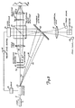
- Figure 1 illustrates a known switching laser beam apparatus for optical recording comprising a gas laser 10 which projects a beam 12 through an acoustic optical modulator 14, a half-wave plate 16, and a diffraction grating 18, which splits the beam into three beams (best seen in Figure 2) comprised of a central read or write beam 20, a read-before-write beam 22 and a read-after-write beam 24.
- the read or write beam 20 is intended to be centered on a recessed track 28 ( Figure 2), on an optical recording surface 30 while the read-before-write beam 22 follows the left-hand edge of the track 28 and the read-after write beam 24 follows the right edge of the track 28.
- the beams are reflected by the optical recording surface 30, and pass back through the objective lens 54 and the quarter-wave plate 52, to be reflected by the polarizing beam splitter 50 towards a cylindrical lens 32 which focuses the read-before-write beam 22 and the read-after-write beam 24 onto track signal detectors 34, 36 respectively, and the read or write beam 20 onto a quad field detector 60.
- a portion of the read or write beam 20 is reflected by the polarizing beam splitter 50 into a level detector 56 which provides a feedback through a power level control circuit 58 to a drive circuit 38 which, in turn, controls the power applied to the acoustic optical modulator 14.
- the power of the write beam is an order of magnitude greater than the power of the read beam.
- the laser 10 is operated at one power level for read operations and a second power level for write operations. This, likewise, causes the read-before-write beam 22 and the read-after-write beam 24, derived as they are from the read or write beam 20, to vary in the same ratio of power.
- the track signal detectors 34, 36 operate by discriminating between small changes in reflected intensity as the corresponding beams on the track 28 cross a track boundary as shown in Figure 2.
- the variations in signal power detected by the track signal detectors 34, 36 are, in turn, fed into a servo system (not shown) which maintains the optical system focused on the centre of the track 28.
- FIG 3 shows a first embodiment of a switching laser beam apparatus according to the present invention for optical recording. Like parts in Figures 1 and 3 have been designated by the same reference numerals.
- a write beam 44 is centred on an optical path 46.
- a mirror 62 having a central aperture, is mounted in the optical path 46 and an attenuator 40 is mounted between the half-wave plate 16 and the diffraction grating 18.
- the mirror 62 is mounted to intersect the write beam 44 and reflect it into the polarizing beam splitter 50 such that it is then reflected by the polarizing beam splitter through the quarter-wave plate 52 and the objective lens 54 onto the optical recording surface 30 at approximately the same location as that of a read beam 42 produced from the laser beam by the diffraction grating 18.
- the write beam is returned to the optical path of the read beam after the diffraction grating 18.
- the drive circuit 38 includes a fixed frequency oscillator 64 whose output is adjusted by a fine frequency adjust circuit 66 responsive to a control signal from the quad field detector 60.
- An adjusted oscillator signal from the adjust circuit 66 is fed to an on/off control circuit 68 which permits the adjusted oscillator signal to pass selectively to an RF amplifier 70.
- the on/off control circuit 68 is responsive to a write signal 72. Essentially when information, such as a "hole" is desired to be written on the optical recording surface 30, the write signal 72 causes the on/off control circuit 68 to pass the adjusted oscillator signal through to the RF amplifier 70.
- the write signal causes the on/off control circuit 68 to block the adjusted oscillator signal.
- the RF amplifier outputs no signal to a transducer 74 of the acoustic optical modulators 14.
- the acoustic optical modulator passes the entire beam 12 through the acoustic optical modulator 14 to the diffraction grating 18 at near maximum intensity.
- the on/off control circuit 68 passes the adjusted oscillator signal onto the RF amplifier 70, the amplified signal from the RF amplifier causes the transducer 74 to induce sonic waves in the acoustic optical modulator 14.
- the interference between the acoustic waves and the beam 12 passing through the acoustic optical modulator causes a portion of the laser beam to be deflected at an angle 6 by so-called Bragg diffraction.
- the write beam when the acoustic optical modulator 14 deflects the write beam 44 along the optical path 46, the write beam impinges on the mirror 62 which reflects it into the polarizing beam splitter 50, which, in turn, reflects the write beam through the quarter-wave plate 52, the objective lens 54 and on to the optical recording surface 30. Until the write beam burns a "hole" in the optical recording surface 30 it reflects back through the objective lens 54, the quarter-wave plate 52, the polarizing beam splitter 50, the central aperture in the mirror 62 and through the cylindrical lens 32 where it impinges on the quad field detector 60.
- a split field detector may be used in place of the quad field detector.
- the quad field detector detects the percentage of the beam lying in four respective quadrants and provides the control signal to the adjust circuit 66 thereby to adjust the Bragg angle 8 of the write beam. It also provides a signal to a servo system (not shown) to compensate for offset of the focusing of the objective lens 54. If a split field detector is used, only adjustment of the Bragg angle 0 is possible.
- the beam 12 passes through the half-wave plate 16 and encounters the attenuator 40.
- the attenuator cuts the power of the beam 12 by an order of magnitude. In the preferred embodiment, the power of the beam is cut to approximately 5% of the original power of the beam.
- the attenuated beam passed through the diffraction grating 18 where it is split into the read beam 42, the read-before-write beam 22 and the read-after-write beam 24, which, after passing through the polarizing beam splitter 50, the quarter-wave plate 52, and the objective lens 54, impinge upon the optical recording surface 30 as shown in Figure 2.
- the beams 22, 24, 42 are reflected back through the objective lens and the quarter-wave plate where they are reflected by the polarizing beam splitter downwards.
- the dotted lines in Figure 3 represent the paths taken by the read-before-write beam and the read-after-write beam.
- the beams 22, 24, 42 pass through the central aperture of the mirror 62, through the cylindrical lens 32 and impinge upon the respective track detectors 34, 36 and the quad field detector 60.
- the impingement of the read-before-write beam and the read-after-write beam on the track signal detectors 34, 36 respectively serve the same servo function as in the known apparatus of Figure 1 but the power level impinging upon these detectors has a maximum predetermined level determined by the maximum power of the beam 12 as attenuated by the attenuator 40.
- the quad field detector 60 detecting the reflected read signal, provides feedback to the servo system to adjust for accurate focusing of the objective lens 54.
- the write beam 44 when it enters the polarizing beam splitter 50 a percentage of the beam is transmitted directly through the polarizing beam splitter 50 and impinges upon the level detector 56.
- the level detector 56 then provides a feedback signal to the power level control circuit 58 which, in turn, provides a power level control signal to the RF amplifier 70 in the drive circuit 38.
- a certain percentage of the read beam 42 is reflected to the level detector 56 by the polarizing beam splitter 50 and the power of the read beam is also dynamically adjusted by the power level control circuit 58 providing the power level control signal to the RF amplifier 70 in the drive circuit 38.
- the implication of the above is as if the beam 12 were being entirely deflected into the optical path of the write beam 46 such that there remained no residual power along the optical path of the read beam 42.
- the percentage of the beam deflected along the optical path 44 which is a first order diffraction path depends upon the amount of power induced into the acoustic optical modulator 14 by the transducer 74.
- the intensity of light in the first order diffraction path is: where 1 0 is the incident intensity and where I is the interaction length, K is the wavelength of the laser light and where is a figure of merit for the material, p being the component of the photoelastic tensor, p the density in g/cc, Va the acoustic velocity in cm/s, n the refractive index of the acoustic medium, P is the acoustic power in watts, and A the cross-sectional area of the acoustic beam in cm 2 . It can be seen from the above equations that the percentage of beam deflected into the first order diffraction path is dependent upon the power of the transducer 74.
- the beam 12 is deflected along the optical path 44 of the write beam 46
- a certain percentage of the beam 12 is deflected along this optical path whilst the remainder continues along the optical path of the read beam 42. It will be appreciated that by controlling the attenuator 40 it is possible to select the appropriate percentage of the power of the beam 12 to be deflected along the optical path 46 so as to minimise or maximise the amount of power used either by the transducer 74 or the amount of power absorbed by the attenuator 40.
- Figure 5 shows a second embodiment of a switching laser beam apparatus according to the present invention.
- the attenuator 40 of Figure 3 has been eliminated so that the read beam 42 is permitted to pass onto the optical recording surface 30 at undiminished power.
- the write beam 44 is constantly "on", but when it is desired not to write, the write beam is deflected into a beam stop 78.
- the write beam is selectively directed along two optical paths: the optical path 46 where it is directed into the mirror 62 and used to write data onto the optical recording surface 30, and an optical path 80 where it is directed into the beam stop 78 when it is not desired to write data onto the optical recording surface 30.
- Data comprising a series of burns or not burned areas or "holes" of the optical recording surface 30 can be written using this switching laser beam apparatus by high frequency switching of the write beam between the optical paths 46, 80.
- the other parts shown in Figure 5 are the same as those shown in Figure 3 and will not be described further.
- Figure 6 shows the drive circuit 38 of the switching laser beam apparatus of Figure 5 necessary to achieve the deflection of the write beam along the optical paths 46, 80.
- the on/off control circuit 68 shown in Figure 4, has been replaced by frequency control circuits 74, 76 and a switch 82 for switching the outputs of the frequency control circuits 74, 76 into the RF amplifier 70.
- the switch 82 is responsive to the write signal 72.
- the output of the frequency control circuit 74 causes the acoustic optical modulator 14 to deflect a percentage of the beam 12 by an angle 0A along the optical path 46.
- the output of the frequency control circuit 76 causes the acoustic optical modulator 14 to deflect a percentage of the beam 12 at an angle ⁇ ⁇ along the optical path 80.
- the actual difference between angles 8A and 6 B need not be very large and in practice should be made small so that the deflection can be made rapidly. Therefore the frequency difference between the outputs of the frequency control circuits 74, 76 are similarly small. It will be appreciated that the frequency of the frequency control circuit 76 is a higher frequency than the frequency of the frequency control circuit 74.
- the power at which the transducer 74 is operated is sufficient to divert approximately 95% of the power of the beam 12 into either the optical path 46 or the optical path 80. The remaining 5% of the power continues along the optical path of the read beam 42.
- the track signal detectors 34, 36 detect the read-before-write beam and the read-after-write beam at a constant power, far less than the power were the right beam transmitted along the optical path of the read beam 42 undiminished in power.
Landscapes
- Physics & Mathematics (AREA)
- Optics & Photonics (AREA)
- Optical Recording Or Reproduction (AREA)
- Optical Head (AREA)
Claims (7)
Applications Claiming Priority (2)
| Application Number | Priority Date | Filing Date | Title |
|---|---|---|---|
| US567610 | 1984-01-03 | ||
| US06/567,610 US4670869A (en) | 1984-01-03 | 1984-01-03 | Switching laser beam apparatus with recombined beam for recording |
Publications (3)
| Publication Number | Publication Date |
|---|---|
| EP0147006A2 EP0147006A2 (de) | 1985-07-03 |
| EP0147006A3 EP0147006A3 (en) | 1988-03-02 |
| EP0147006B1 true EP0147006B1 (de) | 1990-07-11 |
Family
ID=24267896
Family Applications (1)
| Application Number | Title | Priority Date | Filing Date |
|---|---|---|---|
| EP84305526A Expired EP0147006B1 (de) | 1984-01-03 | 1984-08-14 | Schaltgerät für einen Laserstrahl zum optischen Aufzeichnen |
Country Status (6)
| Country | Link |
|---|---|
| US (1) | US4670869A (de) |
| EP (1) | EP0147006B1 (de) |
| JP (1) | JPS60147944A (de) |
| AU (1) | AU568673B2 (de) |
| CA (1) | CA1235811A (de) |
| DE (1) | DE3482692D1 (de) |
Families Citing this family (18)
| Publication number | Priority date | Publication date | Assignee | Title |
|---|---|---|---|---|
| NL8502835A (nl) * | 1985-10-17 | 1987-05-18 | Philips Nv | Inrichting voor het met optische straling aftasten van een informatievlak. |
| JPS62132242A (ja) * | 1985-12-04 | 1987-06-15 | Hitachi Ltd | 光デイスク装置 |
| US5161243A (en) * | 1986-01-21 | 1992-11-03 | Matsushita Electric Industrial Co., Ltd. | Tracking system for an optical recording/reproducing apparatus having a plurality of light spots |
| US5231621A (en) * | 1986-09-05 | 1993-07-27 | Canon Kabushiki Kaisha | Focus detector which serves to split off a portion of a detected light beam only when the detected light beam is not refocused at an expected refocus point |
| US4918675A (en) * | 1986-12-04 | 1990-04-17 | Pencom International Corporation | Magneto-optical head with separate optical paths for error and data detection |
| US4905216A (en) * | 1986-12-04 | 1990-02-27 | Pencom International Corporation | Method for constructing an optical head by varying a hologram pattern |
| JP2613200B2 (ja) * | 1987-01-09 | 1997-05-21 | 株式会社日立製作所 | 光デイスク原盤作製装置 |
| JP2542077Y2 (ja) * | 1988-10-07 | 1997-07-23 | 三洋電機株式会社 | 情報記録再生装置 |
| US4949311A (en) * | 1988-11-22 | 1990-08-14 | Eastman Kodak Company | Single laser direct read after write system (draw) |
| US5128693A (en) * | 1990-09-14 | 1992-07-07 | Nippon Telegraph & Telephone Corporation | Information recording apparatus |
| US5461602A (en) * | 1990-09-14 | 1995-10-24 | Matsushita Electric Industrial Co., Ltd. | Optical recording and reproducing method and apparatus using light beams of two different wavelenghts |
| JP3449769B2 (ja) * | 1993-12-29 | 2003-09-22 | ソニー株式会社 | 光ピックアップ装置 |
| JPH0863749A (ja) * | 1994-08-26 | 1996-03-08 | Nippon Conlux Co Ltd | 光学的情報記録装置および方法 |
| US7027369B1 (en) | 1997-08-19 | 2006-04-11 | Kabushiki Kaisha Kenwood | Optical pickup apparatus for simultaneously reading data from a plurality of tracks of an optical disc |
| JP3480810B2 (ja) * | 1998-06-16 | 2003-12-22 | 富士通株式会社 | 光学的情報記憶装置 |
| US6483797B1 (en) * | 1999-08-20 | 2002-11-19 | Lots Technology, Inc. | Apparatuses and methods for reading after writing in optical recording systems |
| US6980497B2 (en) * | 2001-10-10 | 2005-12-27 | Sanyo Electric Co., Ltd. | Optical disk recording apparatus and control method thereof |
| JP2006155698A (ja) * | 2004-11-26 | 2006-06-15 | Hitachi Ltd | 光記録再生装置 |
Family Cites Families (20)
| Publication number | Priority date | Publication date | Assignee | Title |
|---|---|---|---|---|
| US4000493A (en) * | 1971-04-12 | 1976-12-28 | Eastman Kodak Company | Acoustooptic scanner apparatus and method |
| SE7405076L (sv) * | 1974-04-16 | 1975-10-17 | Erik Gerhard Natanel Westberg | Optiskt massdataminne. |
| US3983317A (en) * | 1974-12-09 | 1976-09-28 | Teletype Corporation | Astigmatizer for laser recording and reproducing system |
| HU175630B (hu) * | 1976-12-15 | 1980-09-28 | Mta Szamitastech Autom Kutato | Lazernoe ustrojstvo dlja registracii dannykh i signalov |
| IL54319A (en) * | 1977-04-22 | 1980-07-31 | Jersey Nuclear Avco Isotopes | Systems for combining and for separating beams of electromagnetic radiation |
| JPS54133305A (en) * | 1978-04-07 | 1979-10-17 | Hitachi Ltd | Information recorder |
| US4180822A (en) * | 1978-04-13 | 1979-12-25 | Rca Corporation | Optical scanner and recorder |
| US4241246A (en) * | 1978-09-29 | 1980-12-23 | Timex Corporation | Thin touch type switch of sealed construction |
| GB2040539B (en) * | 1978-12-27 | 1983-01-26 | Hitachi Ltd | Optical information recording apparatus |
| US4355318A (en) * | 1979-12-27 | 1982-10-19 | Fuji Photo Film Co., Ltd. | Laser recording monitoring system |
| US4357627A (en) * | 1980-04-28 | 1982-11-02 | Xerox Corporation | Method and apparatus for improving resolution of scophony scanning system utilizing carrier phase reversal |
| US4447134A (en) * | 1981-03-23 | 1984-05-08 | Litton Systems, Inc. | Grating signal system using zero order beam of acousto-optic modulator |
| US4459690A (en) * | 1981-07-30 | 1984-07-10 | Rca Corporation | Multi-beam optical record and playback apparatus having an improved beam splitter |
| US4449212A (en) * | 1981-07-30 | 1984-05-15 | Rca Corporation | Multi-beam optical record and playback apparatus |
| JPS5862630A (ja) * | 1981-10-08 | 1983-04-14 | Sony Corp | 光変調装置 |
| NL8104588A (nl) * | 1981-10-08 | 1983-05-02 | Philips Nv | Bundelscheidingsprisma, werkwijze voor het vervaardigen van dit prisma en van dit prisma voorziene optische lees- en/of schrijfeenheid. |
| US4441175A (en) * | 1982-01-25 | 1984-04-03 | Magnetic Peripherals Inc. | Partial beam focus sensing in an optical recording system |
| US4462095A (en) * | 1982-03-19 | 1984-07-24 | Magnetic Peripherals Inc. | Moving diffraction grating for an information track centering system for optical recording |
| US4530573A (en) * | 1982-08-26 | 1985-07-23 | Rca Corporation | Optoelectronic multiposition RF signal switch |
| US4549288A (en) * | 1982-12-20 | 1985-10-22 | North American Philips Corporation | Apparatus for enhancing the playback signal in an optical data recording system |
-
1984
- 1984-01-03 US US06/567,610 patent/US4670869A/en not_active Expired - Fee Related
- 1984-07-16 CA CA000458954A patent/CA1235811A/en not_active Expired
- 1984-07-23 JP JP59152742A patent/JPS60147944A/ja active Pending
- 1984-08-14 EP EP84305526A patent/EP0147006B1/de not_active Expired
- 1984-08-14 DE DE8484305526T patent/DE3482692D1/de not_active Expired - Fee Related
- 1984-08-24 AU AU32352/84A patent/AU568673B2/en not_active Ceased
Also Published As
| Publication number | Publication date |
|---|---|
| EP0147006A3 (en) | 1988-03-02 |
| CA1235811A (en) | 1988-04-26 |
| US4670869A (en) | 1987-06-02 |
| DE3482692D1 (de) | 1990-08-16 |
| AU3235284A (en) | 1985-07-11 |
| AU568673B2 (en) | 1988-01-07 |
| JPS60147944A (ja) | 1985-08-05 |
| EP0147006A2 (de) | 1985-07-03 |
Similar Documents
| Publication | Publication Date | Title |
|---|---|---|
| EP0147006B1 (de) | Schaltgerät für einen Laserstrahl zum optischen Aufzeichnen | |
| EP0050967B1 (de) | Signalerkennungssystem für ein optisches Wiedergabegerät | |
| US4410969A (en) | Optical information playback apparatus | |
| EP0084871A2 (de) | Verfahren und Vorrichtung zur Reduzierung von optischen Rauschen in Halbleiterlasern | |
| EP0745977A1 (de) | Optische Kopfanordnung | |
| EP0044074B1 (de) | Brennpunktdetektor | |
| EP0378438A3 (de) | Optische Abtastvorrichtung | |
| ATE195829T1 (de) | Optische abtastvorrichtung | |
| EP0135750A2 (de) | Aufzeichnungs- und Wiedergabegerät für optische Informationen | |
| US4760565A (en) | High speed track access for optical disks using acousto-optic deflector | |
| KR910003615A (ko) | 광학 기록 및 재생 장치 | |
| US5151888A (en) | Optical information processing apparatus in which the output of an optical sensor is replaced by a reference signal during the occurrence of malfunction | |
| US5046061A (en) | Optical light beam scanner with zero order beam reflector | |
| US4766582A (en) | Optical head | |
| US4682316A (en) | Optical information processing apparatus for light beam focus detection and control | |
| EP0331475A3 (de) | Optisches Informationsberarbeitungsgerät mit einem Verstärkungsregelungssignalspitzenwerterfassungskreis | |
| JPH02183213A (ja) | 自動焦点装置 | |
| US5293372A (en) | Apparatus for optically recording and reproducing information from an optical recording medium | |
| US5253236A (en) | Optical beam focusing and tracking system for an optical disk information storage device | |
| US5088078A (en) | Optical pickup apparatus | |
| US4889415A (en) | Light beam deflector devices | |
| JP2600704B2 (ja) | 光記録再生装置 | |
| HK108095A (en) | Magneto-optical recording and/or reproducing device | |
| JPH03116449A (ja) | 偏光スイッチを利用した合焦方法および装置 | |
| KR100200807B1 (ko) | 초해상의 고밀도 광기록방법 및 이를 이용한 광픽업 |
Legal Events
| Date | Code | Title | Description |
|---|---|---|---|
| PUAI | Public reference made under article 153(3) epc to a published international application that has entered the european phase |
Free format text: ORIGINAL CODE: 0009012 |
|
| AK | Designated contracting states |
Designated state(s): DE FR GB NL |
|
| PUAL | Search report despatched |
Free format text: ORIGINAL CODE: 0009013 |
|
| AK | Designated contracting states |
Kind code of ref document: A3 Designated state(s): DE FR GB NL |
|
| 17P | Request for examination filed |
Effective date: 19880614 |
|
| 17Q | First examination report despatched |
Effective date: 19891025 |
|
| RAP1 | Party data changed (applicant data changed or rights of an application transferred) |
Owner name: CONTROL DATA CORPORATION |
|
| GRAA | (expected) grant |
Free format text: ORIGINAL CODE: 0009210 |
|
| AK | Designated contracting states |
Kind code of ref document: B1 Designated state(s): DE FR GB NL |
|
| ET | Fr: translation filed | ||
| REF | Corresponds to: |
Ref document number: 3482692 Country of ref document: DE Date of ref document: 19900816 |
|
| PG25 | Lapsed in a contracting state [announced via postgrant information from national office to epo] |
Ref country code: GB Effective date: 19900911 |
|
| PG25 | Lapsed in a contracting state [announced via postgrant information from national office to epo] |
Ref country code: NL Effective date: 19910301 |
|
| NLV4 | Nl: lapsed or anulled due to non-payment of the annual fee | ||
| PG25 | Lapsed in a contracting state [announced via postgrant information from national office to epo] |
Ref country code: DE Effective date: 19910501 |
|
| GBPC | Gb: european patent ceased through non-payment of renewal fee | ||
| PLBE | No opposition filed within time limit |
Free format text: ORIGINAL CODE: 0009261 |
|
| STAA | Information on the status of an ep patent application or granted ep patent |
Free format text: STATUS: NO OPPOSITION FILED WITHIN TIME LIMIT |
|
| PG25 | Lapsed in a contracting state [announced via postgrant information from national office to epo] |
Ref country code: FR Effective date: 19910628 |
|
| 26N | No opposition filed | ||
| REG | Reference to a national code |
Ref country code: FR Ref legal event code: ST |
|
| PG25 | Lapsed in a contracting state [announced via postgrant information from national office to epo] |
Ref country code: FR Effective date: 19900831 |