EP0144572A2 - Cathode-magnétron pour la pulvérisation de cibles ferromagnétiques - Google Patents
Cathode-magnétron pour la pulvérisation de cibles ferromagnétiques Download PDFInfo
- Publication number
- EP0144572A2 EP0144572A2 EP84110940A EP84110940A EP0144572A2 EP 0144572 A2 EP0144572 A2 EP 0144572A2 EP 84110940 A EP84110940 A EP 84110940A EP 84110940 A EP84110940 A EP 84110940A EP 0144572 A2 EP0144572 A2 EP 0144572A2
- Authority
- EP
- European Patent Office
- Prior art keywords
- target
- magnetic poles
- ferromagnetic
- magnetic
- pole
- Prior art date
- Legal status (The legal status is an assumption and is not a legal conclusion. Google has not performed a legal analysis and makes no representation as to the accuracy of the status listed.)
- Granted
Links
- 230000005294 ferromagnetic effect Effects 0.000 title claims abstract description 30
- 238000004544 sputter deposition Methods 0.000 title claims abstract description 15
- 230000005291 magnetic effect Effects 0.000 claims abstract description 112
- 229910052751 metal Inorganic materials 0.000 claims abstract description 23
- 239000002184 metal Substances 0.000 claims abstract description 23
- 239000013077 target material Substances 0.000 claims abstract description 20
- 239000003302 ferromagnetic material Substances 0.000 claims abstract description 14
- 239000002826 coolant Substances 0.000 claims abstract description 8
- 230000004907 flux Effects 0.000 claims description 11
- 230000002093 peripheral effect Effects 0.000 claims description 5
- 238000000889 atomisation Methods 0.000 abstract description 13
- 239000000463 material Substances 0.000 description 16
- 239000000696 magnetic material Substances 0.000 description 9
- 230000000694 effects Effects 0.000 description 7
- 230000003628 erosive effect Effects 0.000 description 7
- 238000000034 method Methods 0.000 description 6
- 230000008569 process Effects 0.000 description 6
- XKRFYHLGVUSROY-UHFFFAOYSA-N Argon Chemical compound [Ar] XKRFYHLGVUSROY-UHFFFAOYSA-N 0.000 description 4
- RYGMFSIKBFXOCR-UHFFFAOYSA-N Copper Chemical compound [Cu] RYGMFSIKBFXOCR-UHFFFAOYSA-N 0.000 description 4
- 230000008859 change Effects 0.000 description 4
- 230000005415 magnetization Effects 0.000 description 4
- XEEYBQQBJWHFJM-UHFFFAOYSA-N Iron Chemical compound [Fe] XEEYBQQBJWHFJM-UHFFFAOYSA-N 0.000 description 3
- 229910052802 copper Inorganic materials 0.000 description 3
- 239000010949 copper Substances 0.000 description 3
- 238000013461 design Methods 0.000 description 3
- 238000005457 optimization Methods 0.000 description 3
- 239000000243 solution Substances 0.000 description 3
- 125000006850 spacer group Chemical group 0.000 description 3
- BGPVFRJUHWVFKM-UHFFFAOYSA-N N1=C2C=CC=CC2=[N+]([O-])C1(CC1)CCC21N=C1C=CC=CC1=[N+]2[O-] Chemical compound N1=C2C=CC=CC2=[N+]([O-])C1(CC1)CCC21N=C1C=CC=CC1=[N+]2[O-] BGPVFRJUHWVFKM-UHFFFAOYSA-N 0.000 description 2
- 229910052786 argon Inorganic materials 0.000 description 2
- 238000009826 distribution Methods 0.000 description 2
- 238000010410 dusting Methods 0.000 description 2
- 230000002349 favourable effect Effects 0.000 description 2
- 239000011810 insulating material Substances 0.000 description 2
- 238000004519 manufacturing process Methods 0.000 description 2
- 230000002829 reductive effect Effects 0.000 description 2
- 239000000758 substrate Substances 0.000 description 2
- 238000012360 testing method Methods 0.000 description 2
- 230000008646 thermal stress Effects 0.000 description 2
- 229910000684 Cobalt-chrome Inorganic materials 0.000 description 1
- 229910000831 Steel Inorganic materials 0.000 description 1
- 229910045601 alloy Inorganic materials 0.000 description 1
- 239000000956 alloy Substances 0.000 description 1
- 229910052782 aluminium Inorganic materials 0.000 description 1
- XAGFODPZIPBFFR-UHFFFAOYSA-N aluminium Chemical compound [Al] XAGFODPZIPBFFR-UHFFFAOYSA-N 0.000 description 1
- 230000004323 axial length Effects 0.000 description 1
- 230000008901 benefit Effects 0.000 description 1
- 239000011248 coating agent Substances 0.000 description 1
- 238000000576 coating method Methods 0.000 description 1
- 239000010952 cobalt-chrome Substances 0.000 description 1
- 238000012937 correction Methods 0.000 description 1
- 230000008878 coupling Effects 0.000 description 1
- 238000010168 coupling process Methods 0.000 description 1
- 238000005859 coupling reaction Methods 0.000 description 1
- 230000003247 decreasing effect Effects 0.000 description 1
- 238000010586 diagram Methods 0.000 description 1
- 238000002474 experimental method Methods 0.000 description 1
- 238000002347 injection Methods 0.000 description 1
- 239000007924 injection Substances 0.000 description 1
- 238000009413 insulation Methods 0.000 description 1
- 239000012212 insulator Substances 0.000 description 1
- 229910052742 iron Inorganic materials 0.000 description 1
- 238000010584 magnetic trap Methods 0.000 description 1
- 230000003287 optical effect Effects 0.000 description 1
- 230000036961 partial effect Effects 0.000 description 1
- 239000002245 particle Substances 0.000 description 1
- 229910000889 permalloy Inorganic materials 0.000 description 1
- 238000004080 punching Methods 0.000 description 1
- 230000002441 reversible effect Effects 0.000 description 1
- 238000000926 separation method Methods 0.000 description 1
- 238000005477 sputtering target Methods 0.000 description 1
- 239000010959 steel Substances 0.000 description 1
Images


Classifications
-
- H—ELECTRICITY
- H01—ELECTRIC ELEMENTS
- H01J—ELECTRIC DISCHARGE TUBES OR DISCHARGE LAMPS
- H01J37/00—Discharge tubes with provision for introducing objects or material to be exposed to the discharge, e.g. for the purpose of examination or processing thereof
- H01J37/32—Gas-filled discharge tubes
- H01J37/34—Gas-filled discharge tubes operating with cathodic sputtering
- H01J37/3411—Constructional aspects of the reactor
- H01J37/3441—Dark space shields
-
- H—ELECTRICITY
- H01—ELECTRIC ELEMENTS
- H01J—ELECTRIC DISCHARGE TUBES OR DISCHARGE LAMPS
- H01J37/00—Discharge tubes with provision for introducing objects or material to be exposed to the discharge, e.g. for the purpose of examination or processing thereof
- H01J37/32—Gas-filled discharge tubes
- H01J37/34—Gas-filled discharge tubes operating with cathodic sputtering
- H01J37/3402—Gas-filled discharge tubes operating with cathodic sputtering using supplementary magnetic fields
- H01J37/3405—Magnetron sputtering
- H01J37/3408—Planar magnetron sputtering
-
- H—ELECTRICITY
- H01—ELECTRIC ELEMENTS
- H01J—ELECTRIC DISCHARGE TUBES OR DISCHARGE LAMPS
- H01J37/00—Discharge tubes with provision for introducing objects or material to be exposed to the discharge, e.g. for the purpose of examination or processing thereof
- H01J37/32—Gas-filled discharge tubes
- H01J37/34—Gas-filled discharge tubes operating with cathodic sputtering
- H01J37/3411—Constructional aspects of the reactor
- H01J37/3414—Targets
- H01J37/3426—Material
-
- H—ELECTRICITY
- H01—ELECTRIC ELEMENTS
- H01J—ELECTRIC DISCHARGE TUBES OR DISCHARGE LAMPS
- H01J37/00—Discharge tubes with provision for introducing objects or material to be exposed to the discharge, e.g. for the purpose of examination or processing thereof
- H01J37/32—Gas-filled discharge tubes
- H01J37/34—Gas-filled discharge tubes operating with cathodic sputtering
- H01J37/3488—Constructional details of particle beam apparatus not otherwise provided for, e.g. arrangement, mounting, housing, environment; special provisions for cleaning or maintenance of the apparatus
- H01J37/3497—Temperature of target
Definitions
- the invention relates to a magnetron cathode for sputtering ferromagnetic targets, consisting of a cathode base body with a magnet system with a yoke and on this circumferentially connected, interlocking magnetic poles of opposite polarity, the pole shoes consisting at least partially of target material with the course of the magnetic poles Similar exit surfaces are assigned, behind which in the depth direction of the arrangement, leaving two circumferential air gaps, a circumferentially connected target made of ferromagnetic metal with an atomizing surface is arranged, the magnetic poles and target not overlapping with respect to their projection surfaces in a plane parallel to the atomizing surface and the pole pieces and the target are connected to one another in an electrically conductive manner.
- Magnetron cathodes with flat or curved atomizing surfaces are well known.
- a spatially defined arrangement of permanent and / or electromagnets is provided in such a position relative to the atomizing surface that a ring-shaped tunnel of magnetic field lines is created above the atomizing surface, through which the glow discharge causing the atomizing process is carried out to an area in the immediate vicinity of the atomizing surface limited, thereby increasing the atomization rate by more than a power of ten.
- Sputtering surface refers to the effective target surface exposed to the glow discharge from which the sputtered particles originate, usually the target front surface (DE-AS 24 31 832).
- magnetron cathodes have become known in several variants, which either have a limited application and / or do not fully meet the expectations placed on them.
- the pole faces of the magnet system are arranged behind the target, so that the majority of the magnetic field lines penetrate the target area twice.
- targets made of magnetic materials e.g. are required for the production of magnetic recording tapes, either not or only usable in connection with additional measures.
- a magnetron cathode is known from US Pat. No. 4,198,283, in which the target, which consists of several sections, is clamped between soft magnetic pole pieces. This essentially fulfills the condition that the projections of targets and pole face do not overlap in a common plane parallel to the atomizing surface. Due to the type of clamping, any air gap parallel to the plane mentioned is avoided. This excludes the use of targets made of ferromagnetic materials, because in such a case the magnetic field lines from the pole pieces in the transverse direction into the target would occur so that there is no longer a magnetic tunnel or the magnetron effect.
- DE-PS 30 12 935 In a magnetron cathode known from DE-PS 30 12 935, the magnetic poles of opposite polarity lie between common planes and each have an endless, self-contained, elongated, round course, which can be described as concentric. The magnetic field lines between the inner and outer poles penetrate the distance between these poles. Within this distance there is a geometrically similar, i.e. oblong-round target arranged from the material to be atomized. However, this arrangement is only suitable for the atomization of non-ferromagnetic material. DE-PS 30 12 935 also describes the possibilities for atomizing ferromagnetic targets with the proviso that a second magnetic field is generated by further magnetic devices.
- this second magnetic field should run such that the tendency of the first magnetic field to penetrate the magnetically permeable sputtering surface is substantially reduced.
- This arrangement is very complex with regard to the additionally required magnet system.
- the degree of utilization of the plate-shaped target material would be extremely poor, so that the known solution for ferromagnetic target material is provided in rod or rod form.
- the unpublished DE-OS 33 16 640 discloses a magnetron cathode, in which the one magnetic pole is arranged behind the central part of the target made of magnetic material. This central part, surrounded by an air gap, is surrounded by a peripheral target part, which to a certain extent has the function of pole pieces. Insofar as the peripheral target part is spatially in front of the central target part, magnetic poles of the same type face each other in the air space in front of the central target part, so that no closed tunnel overlapping the central part can be formed from magnetic field lines.
- the magnetic field lines can therefore only enter the central target part in the area of the one circumferential air gap from the peripheral target part, the maximum atomizing effect occurring in the area of the air gap, in the vicinity of which there is relatively little atomizing material. Even special measures must be taken to ensure that material is not atomized from the bottom of the air gap, which in the case of a non-compatible material would contaminate the deposited layers. With such a solution, essentially only material in the immediate vicinity of the air gap can be atomized, so that the degree of material utilization is very low.
- the magnetic field concentration which is harmful for a flat erosion of the target material and is locally high in the area of the single air gap, is even reinforced by the direct coupling of the target parts to the magnetic poles via highly permeable components.
- the air gaps present at this point may be one Do not exceed a gap of about 1 to 2 mm.
- keeping these air gaps small is only possible in view of the necessary length of the permanent magnets in that the pole shoes are provided with collar-shaped extensions on their inner edges.
- the field lines emerging at the collar ends are guided in a very short way into the target material, from which, following the path of least resistance, they re-enter the opposite poles of the permanent magnets, since the ferromagnetic target, the ferromagnetic support plate and the permanent magnets directly without air gaps sit on top of each other.
- the result is a narrow limitation of the "magnetic trap", so that instead of a flat removal of the target material which is desirable per se, two trench-shaped erosion zones below-the collar edges are the result.
- the arrangement of the collars makes the manufacturing process significantly more expensive, which is disadvantageous insofar as the pole shoes themselves take part in the atomization process, so that the result is only a short service life.
- magnetron cathodes are very popular because of their high specific atomization power, on the other hand, the degree of utilization of the target material is very poor due to the magnetron principle.
- the plasma creates deep erosion trenches in the culmination region of the magnetic field lines, which make the target unusable prematurely.
- DE-PS 25 56 607 discloses that the course of the magnetic field lines is periodically shifted by superimposing a second oscillating magnetic field. From DE-OS 27 07 144 it has become known for the same purpose to periodically shift the magnet system parallel to the atomizing surface.
- the invention is therefore based on the object of improving a magnetron cathode of the type described at the outset in such a way that with it ferromagnetic target materials economically, i.e. can be atomized with high specific atomization performance and with high material utilization.
- the problem is solved in the case of the magnetron cathode described at the outset according to the invention in that the pole shoes are separated from the magnetic poles by a distance “S” in which a non-ferromagnetic medium is located, in that the magnetic poles are in a region which is extends in a manner known per se from a plane going through the atomizing surface of the target in the depth direction of the arrangement and that between the pole shoes and the target on the one hand and the magnetic poles on the other hand a thermally conductive metal body is arranged which is connected to at least one coolant channel and does not consist of one -ferromagnetic material.
- the distance “S” is not necessarily the total distance between the underside of the pole shoes and the magnetic poles (in this total distance there may be ferromagnetic flow guide bodies, for example), but a "gap" located outside of ferromagnetic materials.
- opposite magnetic poles face each other in the air space in front of the annular target or in front of the two air gaps, so that the magnetic field lines can also form a "bridge" over the target. So it is not so, and this is in contrast to DE-OS 32 44 691, that the magnetic field lines in a relatively short way beyond the respective bridged air gap back into the target. occur, from which they flow back into the opposite poles of the permanent magnets with low magnetic resistance.
- this way is equipped with the highest possible magnetic resistance, in that the target and the magnetic poles are arranged in such a way that their projection surfaces do not overlap in a plane parallel to the atomizing surface, but in a particularly advantageous embodiment even lie at intervals "x" and that there is no magnetic, highly conductive connection between target and magnet.
- the proportion of the magnetic flux passing through the target can be varied to the proportion of the flux passing through the target (“bridge”).
- This has a direct influence on the geometric shape of the magnetic field lines and thus the plasma trap and the areal distribution of the target consumption.
- the conditions can be easily optimized, so that the atomizing surface remains approximately level even as the target material continues to be used, so that the result is a target utilization of more than 50%, which far exceeds the state of the art .
- pole shoes are not necessary to provide the pole shoes with a collar with a view to the depth extension of the permanent magnets, so that the pole shoes can be manufactured correspondingly cheaply by removing them from a plate-shaped material. This also eliminates the undesirable conductance of the collar-shaped projections on the magnetic flux.
- magnetron cathode Using the magnetron cathode according to the invention, thick targets made of ferromagnetic materials can be atomized. This possibility is given in particular because magnetic saturation of the target material is not necessary. This is associated with an extremely long service life for the magnetron cathode until the target is changed. Nevertheless, a high atomization speed is possible, which would not be possible with thick ferromagnetic targets without using the device according to the invention.
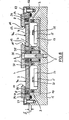
- the magnet system consists of a defined arrangement of permanent magnets 3 and 4, which are connected to a magnet yoke 5 on their rear side without the interposition of an air gap.
- the direction of magnetization is indicated by the arrows in the permanent magnets, and it can be seen that the permanent magnets 3 and 4 have an opposite magnetization direction, which runs in the direction of the legs 5a and 5b of the magnet yoke 5.
- magnetic poles 3a and 4a are formed which run in a common plane.
- the permanent magnets 3 form a circumferentially connected system that can preferably be composed of individual permanent magnets.
- the axis of which is designated A-A the permanent magnets 3 lie in close succession on the circumference of an annular surface which is formed by the upper side of the leg 5a.
- FIGS. 2 and 3 It will be shown with the aid of FIGS. 2 and 3 that the invention is not limited to a rotationally symmetrical system, but can also be used with so-called oval or rectangular cathodes. However, to simplify the description, the following explanations are given using a rotationally symmetrical system.
- the magnetic yoke 5 has the shape of an "E" in cross section, but is cup-shaped.
- the magnetic poles 3a and 4a form a contiguous arrangement on the circumference, which in the case of FIG. 1 is formed concentrically.
- Such a field line is shown on the right in FIG. 1 and is designated by “M”.
- M Magnetic field line
- annular target 7 which also can be composed of sections. Permanent magnets and targets composed of sections are always referred to as "contiguous on the circumference".
- the surface of the target 7 which is effective for coating purposes is its atomizing surface 7a which is directed upwards or outwards.
- magnetic poles 3a and 4a and target 7 do not overlap in a plane parallel to the atomizing surface 7a, but rather lie within one another with the distances "x" mentioned.
- the target 7 consists of a ferromagnetic material. Without the presence of magnetic pole pieces, this would have the consequence that the magnetic field lines penetrate into the target 7 in the shortest possible way, so that the desired field line course known from non-ferromagnetic targets cannot be achieved via this, as shown in FIG 1, right, represented by the dashed line "M". This means that a so-called magnetron effect cannot develop, so that only the usual, very low atomization rate was achieved, as is known from so-called diode systems.
- the magnetic poles 3a and 4a are now assigned pole shoes 8 and 9, their projection surfaces are a circular surface or a circular surface in a plane parallel to the atomizing surface 7a.
- These pole pieces 8 and 9 consist at least partially, ie on their upward or outward-facing surfaces of the same material as the target 7, and are therefore ferromagnetic.
- the pole pieces are in fact subject, albeit slightly, to an atomization process in the area of their exit surfaces (FIG. 10), so that the material of the pole pieces is also deposited on the substrates. Due to the material identity, this is by no means a disadvantage.
- the target and pole pieces can be produced from one and the same plate of ferromagnetic material, for example by punching or burning out, so that an optimal material utilization is possible.
- atomizing the pole pieces does not involve any shifting of the exit surfaces over time. It has been observed that the atomization of the exit surfaces is largely compensated for by the fact that material dusted by the target is deposited on the exit surfaces of the pole shoes, so that the pole shoes are protected by a dynamic balance between dusting and dusting.
- the atomizing surface 7a lies in the same plane as the surfaces of the magnetic poles 3a and 4a. However, deviations from this position are possible, which can also be used to optimize the system (FIGS. 8 to 10).
- Optimization is understood to mean a design of the system with regard to the highest possible atomization rate while simultaneously removing the target material from the atomization surface 7a as uniformly as possible. Whether these requirements are met can be determined by relatively simple tests: a target 7 is atomized over several hours or days and then the remaining geometry of the target 7 is measured. The above-described change in the distances "x" and "s" relative to one another a correction in the sense shown is possible.
- the overlap can be positive as shown in Figure 1, left, i.e. the projection surfaces overlap on a common plane parallel to the atomizing surface 7a.
- the pole shoes 8 and 9 have outlet surfaces 10 and 11 which are closed on the circumference and whose imaginary generatrix runs perpendicular to the atomizing surface 7a.
- the course of the exit surfaces on their circumference is geometrically similar to the course of the magnetic poles and the target edges, i.e. the distances "x" and the extent of the positive or negative overlap "d" are the same over the entire circumference.
- the target 7 has on both sides of the atomizing surface 7a two cylindrical and therefore circumferential side surfaces 7b and 7c, which generally have the described geometrically similar course, in the special case according to FIG. 1, on the right, but in the projection onto a plane parallel to the atomizing surface 7a the exit surfaces 10 and 11 are congruent.
- FIG. 2 sections of magnetron cathodes with different geometric shapes are shown in the top view of the atomizing surface of the target.
- the target width is indicated with "B" by a double arrow.
- the target 7 and pole pieces 8 and 9 have a positive overlap "d” according to FIG. 1, left and FIG. 5.
- the side surfaces 7b and 7c of the target are covered and only shown in broken lines.
- FIG. 2 half H 1 and H 2 of a magnetron cathode according to FIG. 1 are shown above and below, that is, the union of the two halves H 1 and H 2 leads to a rotationally symmetrical magnetron with the common axis AA according to FIG. 1 the two halves H 1 and H 2 form a rectilinear part T, in which all side surfaces, exit surfaces and air gaps open continuously into the corresponding parts of the rotationally symmetrical halves, so that an elongated magnetron cathode of almost any length dimensions results.
- Such magnetron cathodes can be produced with lengths of approximately 4 m, so that they can also be used to coat large-area substrates such as architecture g las is possible.
- the course of the plasma captured by the magnetic fields corresponds to the course of the target 7, so that the term “racetrack” is also used for the closed area in which the plasma is formed.
- the metal body - as drawn - is meandering in cross section, so that the distances or air gaps described above are maintained. Under "air gaps” such distances within the Understand magnet systems that are filled with non-ferromagnetic materials, such as the insulating material 14/15 and the metal body 16, which may consist of aluminum, .Copper or non-magnetic steel.
- the target 7 and the pole pieces 8/9 are at a relatively high level. Potential and are in electrically conductive connection with the metal body, the two connection ends 17a and 17b of the coolant channel 17 must be passed through the cathode base body 1 with a corresponding insulation distance.
- the target 7 is clamped together with the metal body 16 and the coolant channel 17 against the cathode g round body 1 by a plurality of tension screws 18 distributed over the circumference. This is done with the interposition of a pressure plate 19 which also serves for the connection (not shown) for the cathode voltage. The required voltage is isolated by balgele g te insulator 20 and 21.
- the target 7 has on its back a plurality of jacks 7d, each of which carries a thread for the tension screws 18th
- target 7 and pole pieces 8 and 9 are generally at the same potential (cathode potential), it is also possible to provide a potential difference (relative voltage) between the target on the one hand and pole pieces on the other hand.
- a potential difference relative voltage
- target 7 and pole pieces 8/9 must be isolated from one another. This can be done in a simple manner by interposing further insulating bodies which lie on the metal body 16 at suitable points, which are not indicated separately in FIG. 4.
- FIG. 5 shows in solid lines an arrangement which corresponds to that in FIG. 1, left half.
- the magnetic yoke 5 is enlarged radially with unchanged dimensions of the pole shoes 8/9 and also has a longer leg 5d in the axial direction, the annular surface 5e of which in the same plane E 1 lies in which the upper boundary surfaces of the pole pieces 8/9 are also located.
- a magnet 3b is now attached radially inward to this (circumferential) leg 5d, which corresponds to the magnet 3, but lies opposite the outer cylindrical surface of the pole piece 8. This increases the distance to the target 7, so that a larger proportion of the magnetic flux enters the pole piece 8.
- the overlap "d" is positive in FIG. 5.
- Figure 6 shows an analog arrangement, but with the difference that in this case the overlap "d" is negative is, as has already been described above.
- Such a measure facilitates the removal of the target 7, since this can be removed upwards through the space between the pole pieces 8 and 9. It can also be seen in particular that the two pole pieces 8 and 9 of opposite polarity lie between the same planes E i and E2.
- FIG. 7 again shows an analog arrangement, and likewise with a negative overlap "d".
- a permanent magnet 23 has been stepped in place, which is magnetized radially in accordance with the arrow.
- the pole faces are connected to a cylindrical, ferromagnetic core 24 and to a ferromagnetic hollow cylinder 25, on the upper end faces of which the magnetic poles 4a and 3a are formed.
- the course of the magnetic flux is essentially the same as in the previous embodiments, but the arrangement of the permanent magnet 23 or - with an elongated arrangement of the permanent magnets - is simpler designed. Designs are also conceivable in which the magnet system 2 consists of a piece of a hard magnetic material that is magnetized in a suitable manner.
- the cathode base body 1 is not identical to the magnetic yoke, but is designed as an additional hollow body, and closed by the metal body 16, which is designed here as a plane-parallel plate made of an amagnetic material (copper).
- the seal compared to the cathode base body 1 is effected by unspecified round cord seals and lag screws 27 and 28.
- a coolant channel 17 Between the metal. Body 16 and the cathode base body 1 is a coolant channel 17 in which the permanent magnets 3 and 4 and the magnetic yoke are housed. Fastening is carried out using insulating bodies 27 and lag screws 28.
- the ring-shaped closed target 7 as well as the central pole piece 9 and the peripheral pole pieces 8 are arranged.
- the pole shoes 8 and 9 are attached to spacers 29 and 30, which have a height that is about the width of the air gaps 12 and 13 is greater than the thickness of the target 7. Since this increases the distance between the pole pieces 8 and 9 and the associated magnetic poles of the permanent magnets 3 and 4, the distance between the top of the metal body 16 and the bottom of the pole pieces 8 and 9 is due to ferromagnetic bodies 34 and 35 bridges, which are arranged within the spacers 29 and 30 made of non-magnetic material.
- the outer bodies 34 and the inner bodies 35 are designed as strips, the course of which follows the course of the pole shoes 8.
- the distance "S" is made up of the thickness of the metal body 16 and the distance between the magnetic poles and the inside of the metal body 16. As already explained above, it is important to maintain such a distance, which represents a magnetic resistance of considerable size, with regard to the flow distribution between the target 7 on the one hand and the pole pieces 8 and 9 on the other hand.
- FIG. 8 shows that the projections of the permanent magnets 3 and 4 and of the ferromagnetic bodies 34 and 35 on a common plane parallel to the target surface 7a need not be congruent. Rather, as shown, a considerable lateral offset is possible. This also makes it possible to change the relative proportions of the magnetic flux entering the target 7 on the one hand and the pole shoes 8 and 9 on the other hand, a magnetic short circuit between the ferromagnetic bodies 34 and 35 and the target 7 having to be prevented under all circumstances. For this reason is between the ferromagnetic bodies 34 and 35 and the target 7 each also have a corresponding section of the spacers 29 and 30 made of non-magnetic material.
- FIG. 9 only the target 7 and the pole shoes 8 and 9 above the flat metal body 16 are shown in FIG. 8, and the position of the air gaps 12 and 13 in relation to the atomizing surface 7a can also be seen.
- the axis of the magnetron is labeled "A”, i.e. only the parts of a h a 1 b e n magnetron are shown.
- the course of the horizontal component H of the magnetic field strength is plotted in the upper part of FIG. 9 with exact radial assignment to the axis A, namely the field strength at a distance of 2 mm above the pole shoe surface 8a or 9a. It can be seen that the horizontal component has a maximum in the area of the exit surfaces 10 and 11. However, the curve does not go through zero between the maxima, but even at the location of the minimum, which lies above the center of the target cross section, there is still a considerable horizontal component.
- the course of the curve lying between the two maxima is evidence of the existence of a "bridge" of magnetic field lines F 1 which crosses target 7 and which are present in addition to field lines F 2 directly entering target 7 (FIG. 10). This bridge is the same with that of the previous ones known planar magnetrons existing "magnetic tunnel” comparable. This ensures effective plasma injection in the entire target area, which leads to the extremely flat erosion profile observed (see FIG. 10).
- the ferromagnetic bodies 34 and 35 are also present in the arrangement according to FIG. Attempts to omit the. outer ferromagnetic body 34 have not shown the same favorable result as the tests with an arrangement according to Figure 8.
- the outer ferromagnetic body 34 the magnetic field was in particular in the middle of the target cross section and on the outer target edge significantly increased, so that a more even removal of the target material resulted. This was also reflected in the optical observation of the plasma, which was distributed almost homogeneously over the entire target width at a pressure of 5 x 10 -3 mbar. Based on the atomizing surface 7a, a specific atomizing power of 22.0 w cm -2 was maintained in continuous operation.
- FIG. 10 shows the same parts of the device as hatched in FIG. 9, specifically before the start of the first sputtering process.
- the dashed line shows the location of the Surfaces of the pole shoes 8 and 9 on the one hand and the target 7 on the other hand after the magnetron cathode has been in use for a total of 82 hours. It can be seen that the utilization of the target material is above average evenly over the entire target cross-section and that the feared V-shaped erosion trenches, which occur even when sputtering non-ferromagnetic materials, have not occurred. This process is all the more remarkable since there are no additional aids for the mechanical or electrical movement of the magnetic field.
- FIG. 11 shows a typical magnetron characteristic curve, as was obtained when the magnetron according to FIG. 8 was operated at an argon pressure of 5 ⁇ 10 -3 mbar. From a voltage value of about 400 V, the cathode current I could be increased considerably by a relatively small voltage increase in a linear dependence, which is common for the operation of planar magnetrons with non-ferromagnetic targets. The end point of the characteristic curve shown corresponds to an average power density on the target of 22 W cm -2 .
Landscapes
- Physics & Mathematics (AREA)
- Engineering & Computer Science (AREA)
- Plasma & Fusion (AREA)
- Chemical & Material Sciences (AREA)
- Analytical Chemistry (AREA)
- Physical Vapour Deposition (AREA)
- Thin Magnetic Films (AREA)
Priority Applications (1)
| Application Number | Priority Date | Filing Date | Title |
|---|---|---|---|
| AT84110940T ATE47504T1 (de) | 1983-12-05 | 1984-09-13 | Magnetronkatode zum zerstaeuben ferromagnetischer targets. |
Applications Claiming Priority (2)
| Application Number | Priority Date | Filing Date | Title |
|---|---|---|---|
| DE3343904 | 1983-12-05 | ||
| DE3343904 | 1983-12-05 |
Publications (3)
| Publication Number | Publication Date |
|---|---|
| EP0144572A2 true EP0144572A2 (fr) | 1985-06-19 |
| EP0144572A3 EP0144572A3 (en) | 1986-07-30 |
| EP0144572B1 EP0144572B1 (fr) | 1989-10-18 |
Family
ID=6216066
Family Applications (1)
| Application Number | Title | Priority Date | Filing Date |
|---|---|---|---|
| EP84110940A Expired EP0144572B1 (fr) | 1983-12-05 | 1984-09-13 | Cathode-magnétron pour la pulvérisation de cibles ferromagnétiques |
Country Status (6)
| Country | Link |
|---|---|
| US (1) | US4572776A (fr) |
| EP (1) | EP0144572B1 (fr) |
| JP (1) | JPS60138070A (fr) |
| KR (1) | KR910009249B1 (fr) |
| AT (1) | ATE47504T1 (fr) |
| DE (1) | DE3480245D1 (fr) |
Cited By (6)
| Publication number | Priority date | Publication date | Assignee | Title |
|---|---|---|---|---|
| DE3601439C1 (de) * | 1986-01-20 | 1987-04-09 | Glyco Metall Werke | Schichtverbundwerkstoff,insbesondere fuer Gleit- und Reibelemente,sowie Verfahren zu seiner Herstellung |
| EP0334347A1 (fr) * | 1988-03-25 | 1989-09-27 | ELAN Elektronische Anlagen GmbH | Dispositif de pulvérisation cathodique |
| EP0187226B1 (fr) * | 1984-11-14 | 1990-01-31 | Hitachi, Ltd. | Appareil de pulvérisation dans lequel la formation du film est directive |
| DE4000941A1 (de) * | 1989-01-20 | 1990-08-02 | Ulvac Corp | Magnetron-zerstaeubungsquelle |
| DE19648390A1 (de) * | 1995-09-27 | 1998-05-28 | Leybold Materials Gmbh | Target für die Sputterkathode einer Vakuumbeschichtungsanlage |
| EP4283011A1 (fr) * | 2022-05-26 | 2023-11-29 | Instytut Fizyki Polskiej Akademii Nauk | Dispositif à magnétron pour une cible de pulvérisation |
Families Citing this family (41)
| Publication number | Priority date | Publication date | Assignee | Title |
|---|---|---|---|---|
| JPH0689443B2 (ja) * | 1984-11-14 | 1994-11-09 | 株式会社日立製作所 | スパツタリング用タ−ゲツト |
| DE3527626A1 (de) * | 1985-08-01 | 1987-02-05 | Leybold Heraeus Gmbh & Co Kg | Zerstaeubungskatode nach dem magnetronprinzip |
| US4855033A (en) * | 1986-04-04 | 1989-08-08 | Materials Research Corporation | Cathode and target design for a sputter coating apparatus |
| CA1308060C (fr) * | 1986-04-04 | 1992-09-29 | Tokyo Electron Limited | Conception de cathode et de cible pour appareil d'enduction par pulverisation |
| DE3624150C2 (de) * | 1986-07-17 | 1994-02-24 | Leybold Ag | Zerstäubungskatode nach dem Magnetronprinzip |
| JPH07107188B2 (ja) * | 1986-09-12 | 1995-11-15 | 松下電器産業株式会社 | スパッタリングターゲット |
| US4892633A (en) * | 1988-11-14 | 1990-01-09 | Vac-Tec Systems, Inc. | Magnetron sputtering cathode |
| US4865708A (en) * | 1988-11-14 | 1989-09-12 | Vac-Tec Systems, Inc. | Magnetron sputtering cathode |
| JPH02243761A (ja) * | 1989-03-15 | 1990-09-27 | Ulvac Corp | マグネトロンスパッタリング源用電磁石の制御方法 |
| DE4018914C1 (fr) * | 1990-06-13 | 1991-06-06 | Leybold Ag, 6450 Hanau, De | |
| US5080772A (en) * | 1990-08-24 | 1992-01-14 | Materials Research Corporation | Method of improving ion flux distribution uniformity on a substrate |
| DE4120690A1 (de) * | 1991-06-22 | 1992-12-24 | Leybold Ag | Targetvorrichtung aus ferromagnetischem material fuer eine magnetron-elektrode |
| US5174880A (en) * | 1991-08-05 | 1992-12-29 | Hmt Technology Corporation | Magnetron sputter gun target assembly with distributed magnetic field |
| DE4135939A1 (de) * | 1991-10-31 | 1993-05-06 | Leybold Ag, 6450 Hanau, De | Zerstaeubungskathode |
| US5407551A (en) * | 1993-07-13 | 1995-04-18 | The Boc Group, Inc. | Planar magnetron sputtering apparatus |
| JP3886209B2 (ja) * | 1997-06-02 | 2007-02-28 | 貞夫 門倉 | 対向ターゲット式スパッタ装置 |
| US6235170B1 (en) * | 1998-06-10 | 2001-05-22 | David A. Glocker | Conical sputtering target |
| US6432286B1 (en) * | 1998-06-10 | 2002-08-13 | David A. Glocker | Conical sputtering target |
| US6224725B1 (en) * | 1999-02-09 | 2001-05-01 | Isoflux, Inc. | Unbalanced magnetron sputtering with auxiliary cathode |
| US6359388B1 (en) | 2000-08-28 | 2002-03-19 | Guardian Industries Corp. | Cold cathode ion beam deposition apparatus with segregated gas flow |
| US6783638B2 (en) * | 2001-09-07 | 2004-08-31 | Sputtered Films, Inc. | Flat magnetron |
| GB0126721D0 (en) * | 2001-11-07 | 2002-01-02 | Bellido Gonzalez V | Ferromagnetic magnetron |
| US6988463B2 (en) * | 2002-10-18 | 2006-01-24 | Guardian Industries Corp. | Ion beam source with gas introduced directly into deposition/vacuum chamber |
| US6812648B2 (en) | 2002-10-21 | 2004-11-02 | Guardian Industries Corp. | Method of cleaning ion source, and corresponding apparatus/system |
| US8440301B2 (en) * | 2006-07-13 | 2013-05-14 | Teer Coatings Limited | Coating apparatus and method |
| JP5265149B2 (ja) | 2006-07-21 | 2013-08-14 | アプライド マテリアルズ インコーポレイテッド | マルチカソード設計用冷却暗部シールド |
| US20080083611A1 (en) * | 2006-10-06 | 2008-04-10 | Tegal Corporation | High-adhesive backside metallization |
| CN101720493B (zh) * | 2007-06-15 | 2012-08-15 | Oc欧瑞康巴尔斯公司 | 多靶溅射源及沉积多层的方法 |
| US8808513B2 (en) * | 2008-03-25 | 2014-08-19 | Oem Group, Inc | Stress adjustment in reactive sputtering |
| US20090246385A1 (en) * | 2008-03-25 | 2009-10-01 | Tegal Corporation | Control of crystal orientation and stress in sputter deposited thin films |
| US20100018857A1 (en) * | 2008-07-23 | 2010-01-28 | Seagate Technology Llc | Sputter cathode apparatus allowing thick magnetic targets |
| US8482375B2 (en) * | 2009-05-24 | 2013-07-09 | Oem Group, Inc. | Sputter deposition of cermet resistor films with low temperature coefficient of resistance |
| TWI338721B (en) * | 2009-10-16 | 2011-03-11 | Suntek Prec Corp | A sputtering apparatus with a side target and a method for sputtering a workpiece having non-planer surfaces |
| JP5853487B2 (ja) * | 2010-08-19 | 2016-02-09 | 東レ株式会社 | 放電電極及び放電方法 |
| US8575565B2 (en) | 2011-10-10 | 2013-11-05 | Guardian Industries Corp. | Ion source apparatus and methods of using the same |
| DE102013112861B4 (de) * | 2013-01-15 | 2018-11-15 | VON ARDENNE Asset GmbH & Co. KG | Magnetronanordnung und Target für eine Magnetronanordnung |
| US9328410B2 (en) | 2013-10-25 | 2016-05-03 | First Solar, Inc. | Physical vapor deposition tile arrangement and physical vapor deposition arrangement |
| TWI618809B (zh) * | 2016-08-31 | 2018-03-21 | Linco Technology Co Ltd | 具高靶材利用率之磁性靶材陰極裝置 |
| CN111996504A (zh) * | 2020-07-10 | 2020-11-27 | 包头稀土研究院 | 铁磁性靶材磁控溅射装置 |
| CN111996505B (zh) * | 2020-07-10 | 2023-07-14 | 包头稀土研究院 | 磁控溅射铁磁性靶材的装置 |
| CN114574830B (zh) * | 2022-03-11 | 2024-03-26 | 陕西理工大学 | 用于磁控溅射靶阴极的磁铁布置结构 |
Family Cites Families (5)
| Publication number | Priority date | Publication date | Assignee | Title |
|---|---|---|---|---|
| US4198283A (en) * | 1978-11-06 | 1980-04-15 | Materials Research Corporation | Magnetron sputtering target and cathode assembly |
| US4299678A (en) * | 1979-07-23 | 1981-11-10 | Spin Physics, Inc. | Magnetic target plate for use in magnetron sputtering of magnetic films |
| JPS5893872A (ja) * | 1981-11-30 | 1983-06-03 | Anelva Corp | スパツタリング装置 |
| US4391697A (en) * | 1982-08-16 | 1983-07-05 | Vac-Tec Systems, Inc. | High rate magnetron sputtering of high permeability materials |
| US4414086A (en) * | 1982-11-05 | 1983-11-08 | Varian Associates, Inc. | Magnetic targets for use in sputter coating apparatus |
-
1984
- 1984-09-13 EP EP84110940A patent/EP0144572B1/fr not_active Expired
- 1984-09-13 AT AT84110940T patent/ATE47504T1/de not_active IP Right Cessation
- 1984-09-13 DE DE8484110940T patent/DE3480245D1/de not_active Expired
- 1984-12-04 KR KR1019840007652A patent/KR910009249B1/ko not_active Expired
- 1984-12-05 US US06/678,597 patent/US4572776A/en not_active Expired - Lifetime
- 1984-12-05 JP JP59255875A patent/JPS60138070A/ja active Granted
Cited By (7)
| Publication number | Priority date | Publication date | Assignee | Title |
|---|---|---|---|---|
| EP0187226B1 (fr) * | 1984-11-14 | 1990-01-31 | Hitachi, Ltd. | Appareil de pulvérisation dans lequel la formation du film est directive |
| DE3601439C1 (de) * | 1986-01-20 | 1987-04-09 | Glyco Metall Werke | Schichtverbundwerkstoff,insbesondere fuer Gleit- und Reibelemente,sowie Verfahren zu seiner Herstellung |
| US4832809A (en) * | 1986-01-20 | 1989-05-23 | Glyco-Metall-Werke Daelan & Loos Gmbh | Process for preparation layered composite constructional material, especially for sliding and friction members |
| EP0334347A1 (fr) * | 1988-03-25 | 1989-09-27 | ELAN Elektronische Anlagen GmbH | Dispositif de pulvérisation cathodique |
| DE4000941A1 (de) * | 1989-01-20 | 1990-08-02 | Ulvac Corp | Magnetron-zerstaeubungsquelle |
| DE19648390A1 (de) * | 1995-09-27 | 1998-05-28 | Leybold Materials Gmbh | Target für die Sputterkathode einer Vakuumbeschichtungsanlage |
| EP4283011A1 (fr) * | 2022-05-26 | 2023-11-29 | Instytut Fizyki Polskiej Akademii Nauk | Dispositif à magnétron pour une cible de pulvérisation |
Also Published As
| Publication number | Publication date |
|---|---|
| KR910009249B1 (ko) | 1991-11-07 |
| KR850005004A (ko) | 1985-08-19 |
| JPS60138070A (ja) | 1985-07-22 |
| EP0144572A3 (en) | 1986-07-30 |
| DE3480245D1 (en) | 1989-11-23 |
| US4572776A (en) | 1986-02-25 |
| ATE47504T1 (de) | 1989-11-15 |
| EP0144572B1 (fr) | 1989-10-18 |
| JPH0373633B2 (fr) | 1991-11-22 |
Similar Documents
| Publication | Publication Date | Title |
|---|---|---|
| EP0144572B1 (fr) | Cathode-magnétron pour la pulvérisation de cibles ferromagnétiques | |
| EP0144838B1 (fr) | Cathode-magnétron pour la pulvérisation de cibles ferromagnétiques | |
| DE3177309T2 (de) | Mittels magnetische Mitteln verbesserte Zerstäubungsquelle. | |
| DE2431832B2 (de) | Kathodenzerstäubungsgerät | |
| EP0210473B1 (fr) | Cathode de pulvérisation selon le principe magnétron | |
| EP0253344B1 (fr) | Cathode de pulvérisation selon le principe magnétron | |
| DE3135208C2 (fr) | ||
| DE19853943B4 (de) | Katode zur Zerstäubung oder Bogenaufdampfung sowie Vorrichtung zur Beschichtung oder Ionenimplantation mit einer solchen Katode | |
| DE3339482A1 (de) | Magnetisches zerstaeubungstarget | |
| EP0461525B1 (fr) | Procédé et dispositif pour revêtement d'un substrat utilisant une cathode-magnétron | |
| EP0242826A2 (fr) | Cathode de pulvérisation magnétron | |
| DE2264437A1 (de) | Mit hochfrequenz-spannung betriebene entladungsvorrichtung | |
| DE69605840T2 (de) | Magnetron Zerstäubungssystem | |
| DE3012935C2 (de) | Zerstäubungsvorrichtung mit magnetischer Verstärkung | |
| DE3331406A1 (de) | Zerstaeubungskatode | |
| DE3429988A1 (de) | Magnetronkatode zum zerstaeuben ferromagnetischer targets | |
| DE69027344T2 (de) | Magnetronzerstäubungsanlage | |
| DE3226717A1 (de) | System und verfahren zum sputtern mit einer hohen rate | |
| EP0316523A2 (fr) | Cathode pour pulvérisation selon le principe magnétron | |
| DE19623359A1 (de) | Vorrichtung zum Beschichten eines Substrats | |
| DE3244691C2 (fr) | ||
| DE3411536C2 (fr) | ||
| DE3442206C2 (fr) | ||
| DE4127261C1 (en) | Sputtering equipment for coating large substrates with ferromagnetic and non-magnetic material - has cathode target comprising sub-targets, and cooling plates contg. magnet unit and poles shoes | |
| DE4304581A1 (de) | Vorrichtung zum Beschichten eines Substrats |
Legal Events
| Date | Code | Title | Description |
|---|---|---|---|
| PUAI | Public reference made under article 153(3) epc to a published international application that has entered the european phase |
Free format text: ORIGINAL CODE: 0009012 |
|
| AK | Designated contracting states |
Designated state(s): AT BE CH DE FR GB IT LI LU NL SE |
|
| RTI1 | Title (correction) | ||
| PUAL | Search report despatched |
Free format text: ORIGINAL CODE: 0009013 |
|
| AK | Designated contracting states |
Kind code of ref document: A3 Designated state(s): AT BE CH DE FR GB IT LI LU NL SE |
|
| 17P | Request for examination filed |
Effective date: 19870114 |
|
| 17Q | First examination report despatched |
Effective date: 19880419 |
|
| RAP1 | Party data changed (applicant data changed or rights of an application transferred) |
Owner name: LEYBOLD AKTIENGESELLSCHAFT |
|
| GRAA | (expected) grant |
Free format text: ORIGINAL CODE: 0009210 |
|
| AK | Designated contracting states |
Kind code of ref document: B1 Designated state(s): AT BE CH DE FR GB IT LI LU NL SE |
|
| REF | Corresponds to: |
Ref document number: 47504 Country of ref document: AT Date of ref document: 19891115 Kind code of ref document: T |
|
| ET | Fr: translation filed | ||
| ITF | It: translation for a ep patent filed | ||
| GBT | Gb: translation of ep patent filed (gb section 77(6)(a)/1977) | ||
| REF | Corresponds to: |
Ref document number: 3480245 Country of ref document: DE Date of ref document: 19891123 |
|
| PLBE | No opposition filed within time limit |
Free format text: ORIGINAL CODE: 0009261 |
|
| STAA | Information on the status of an ep patent application or granted ep patent |
Free format text: STATUS: NO OPPOSITION FILED WITHIN TIME LIMIT |
|
| 26N | No opposition filed | ||
| PGFP | Annual fee paid to national office [announced via postgrant information from national office to epo] |
Ref country code: FR Payment date: 19930809 Year of fee payment: 10 |
|
| PGFP | Annual fee paid to national office [announced via postgrant information from national office to epo] |
Ref country code: AT Payment date: 19930810 Year of fee payment: 10 |
|
| PGFP | Annual fee paid to national office [announced via postgrant information from national office to epo] |
Ref country code: SE Payment date: 19930813 Year of fee payment: 10 |
|
| PGFP | Annual fee paid to national office [announced via postgrant information from national office to epo] |
Ref country code: GB Payment date: 19930816 Year of fee payment: 10 |
|
| PGFP | Annual fee paid to national office [announced via postgrant information from national office to epo] |
Ref country code: BE Payment date: 19930823 Year of fee payment: 10 |
|
| PGFP | Annual fee paid to national office [announced via postgrant information from national office to epo] |
Ref country code: LU Payment date: 19930903 Year of fee payment: 10 |
|
| ITTA | It: last paid annual fee | ||
| PGFP | Annual fee paid to national office [announced via postgrant information from national office to epo] |
Ref country code: NL Payment date: 19930930 Year of fee payment: 10 |
|
| EPTA | Lu: last paid annual fee | ||
| PG25 | Lapsed in a contracting state [announced via postgrant information from national office to epo] |
Ref country code: LU Free format text: LAPSE BECAUSE OF NON-PAYMENT OF DUE FEES Effective date: 19940913 Ref country code: GB Effective date: 19940913 Ref country code: AT Effective date: 19940913 |
|
| PG25 | Lapsed in a contracting state [announced via postgrant information from national office to epo] |
Ref country code: SE Effective date: 19940914 |
|
| PG25 | Lapsed in a contracting state [announced via postgrant information from national office to epo] |
Ref country code: BE Effective date: 19940930 |
|
| EAL | Se: european patent in force in sweden |
Ref document number: 84110940.8 |
|
| BERE | Be: lapsed |
Owner name: LEYBOLD A.G. Effective date: 19940930 |
|
| PG25 | Lapsed in a contracting state [announced via postgrant information from national office to epo] |
Ref country code: NL Effective date: 19950401 |
|
| GBPC | Gb: european patent ceased through non-payment of renewal fee |
Effective date: 19940913 |
|
| NLV4 | Nl: lapsed or anulled due to non-payment of the annual fee | ||
| PG25 | Lapsed in a contracting state [announced via postgrant information from national office to epo] |
Ref country code: FR Effective date: 19950531 |
|
| EUG | Se: european patent has lapsed |
Ref document number: 84110940.8 |
|
| REG | Reference to a national code |
Ref country code: FR Ref legal event code: ST |
|
| PGFP | Annual fee paid to national office [announced via postgrant information from national office to epo] |
Ref country code: DE Payment date: 19980826 Year of fee payment: 15 |
|
| PGFP | Annual fee paid to national office [announced via postgrant information from national office to epo] |
Ref country code: CH Payment date: 19980827 Year of fee payment: 15 |
|
| PG25 | Lapsed in a contracting state [announced via postgrant information from national office to epo] |
Ref country code: LI Free format text: LAPSE BECAUSE OF NON-PAYMENT OF DUE FEES Effective date: 19990930 Ref country code: CH Free format text: LAPSE BECAUSE OF NON-PAYMENT OF DUE FEES Effective date: 19990930 |
|
| REG | Reference to a national code |
Ref country code: CH Ref legal event code: PL |
|
| PG25 | Lapsed in a contracting state [announced via postgrant information from national office to epo] |
Ref country code: DE Free format text: LAPSE BECAUSE OF NON-PAYMENT OF DUE FEES Effective date: 20000701 |