EP0144513A1 - Device for the mechanical dividing of cheese loafs or blocks - Google Patents
Device for the mechanical dividing of cheese loafs or blocks Download PDFInfo
- Publication number
- EP0144513A1 EP0144513A1 EP84108799A EP84108799A EP0144513A1 EP 0144513 A1 EP0144513 A1 EP 0144513A1 EP 84108799 A EP84108799 A EP 84108799A EP 84108799 A EP84108799 A EP 84108799A EP 0144513 A1 EP0144513 A1 EP 0144513A1
- Authority
- EP
- European Patent Office
- Prior art keywords
- cheese
- cutting
- pieces
- elements
- base plate
- Prior art date
- Legal status (The legal status is an assumption and is not a legal conclusion. Google has not performed a legal analysis and makes no representation as to the accuracy of the status listed.)
- Granted
Links
- 235000013351 cheese Nutrition 0.000 title claims abstract description 70
- 238000005520 cutting process Methods 0.000 claims abstract description 72
- 238000000034 method Methods 0.000 claims description 20
- 239000007788 liquid Substances 0.000 claims description 2
- 239000007921 spray Substances 0.000 claims description 2
- XLYOFNOQVPJJNP-UHFFFAOYSA-N water Substances O XLYOFNOQVPJJNP-UHFFFAOYSA-N 0.000 claims description 2
- 230000007423 decrease Effects 0.000 claims 1
- 206010039509 Scab Diseases 0.000 description 8
- 235000011617 hard cheese Nutrition 0.000 description 7
- 229910000831 Steel Inorganic materials 0.000 description 5
- 239000010959 steel Substances 0.000 description 5
- 235000013305 food Nutrition 0.000 description 3
- 238000005219 brazing Methods 0.000 description 2
- 238000010276 construction Methods 0.000 description 2
- 229920003023 plastic Polymers 0.000 description 2
- 239000004033 plastic Substances 0.000 description 2
- 230000001681 protective effect Effects 0.000 description 2
- 239000007787 solid Substances 0.000 description 2
- 241000251730 Chondrichthyes Species 0.000 description 1
- 208000011092 Hand injury Diseases 0.000 description 1
- 240000002129 Malva sylvestris Species 0.000 description 1
- 235000006770 Malva sylvestris Nutrition 0.000 description 1
- VVQNEPGJFQJSBK-UHFFFAOYSA-N Methyl methacrylate Chemical compound COC(=O)C(C)=C VVQNEPGJFQJSBK-UHFFFAOYSA-N 0.000 description 1
- 229920005372 Plexiglas® Polymers 0.000 description 1
- 206010041953 Staring Diseases 0.000 description 1
- 239000004809 Teflon Substances 0.000 description 1
- 229920006362 Teflon® Polymers 0.000 description 1
- 208000027418 Wounds and injury Diseases 0.000 description 1
- 230000015572 biosynthetic process Effects 0.000 description 1
- 230000003749 cleanliness Effects 0.000 description 1
- 238000000576 coating method Methods 0.000 description 1
- 230000006378 damage Effects 0.000 description 1
- 238000009826 distribution Methods 0.000 description 1
- 239000000835 fiber Substances 0.000 description 1
- 210000004247 hand Anatomy 0.000 description 1
- 208000014674 injury Diseases 0.000 description 1
- 238000004519 manufacturing process Methods 0.000 description 1
- 238000004806 packaging method and process Methods 0.000 description 1
- 235000014059 processed cheese Nutrition 0.000 description 1
- 235000008983 soft cheese Nutrition 0.000 description 1
- 230000006641 stabilisation Effects 0.000 description 1
- 238000011105 stabilization Methods 0.000 description 1
- 230000004936 stimulating effect Effects 0.000 description 1
- 210000002435 tendon Anatomy 0.000 description 1
- 238000003466 welding Methods 0.000 description 1
- 210000000707 wrist Anatomy 0.000 description 1
Images


Classifications
-
- B—PERFORMING OPERATIONS; TRANSPORTING
- B26—HAND CUTTING TOOLS; CUTTING; SEVERING
- B26D—CUTTING; DETAILS COMMON TO MACHINES FOR PERFORATING, PUNCHING, CUTTING-OUT, STAMPING-OUT OR SEVERING
- B26D1/00—Cutting through work characterised by the nature or movement of the cutting member or particular materials not otherwise provided for; Apparatus or machines therefor; Cutting members therefor
- B26D1/01—Cutting through work characterised by the nature or movement of the cutting member or particular materials not otherwise provided for; Apparatus or machines therefor; Cutting members therefor involving a cutting member which does not travel with the work
- B26D1/02—Cutting through work characterised by the nature or movement of the cutting member or particular materials not otherwise provided for; Apparatus or machines therefor; Cutting members therefor involving a cutting member which does not travel with the work having a stationary cutting member
- B26D1/03—Cutting through work characterised by the nature or movement of the cutting member or particular materials not otherwise provided for; Apparatus or machines therefor; Cutting members therefor involving a cutting member which does not travel with the work having a stationary cutting member with a plurality of cutting members
-
- A—HUMAN NECESSITIES
- A01—AGRICULTURE; FORESTRY; ANIMAL HUSBANDRY; HUNTING; TRAPPING; FISHING
- A01J—MANUFACTURE OF DAIRY PRODUCTS
- A01J27/00—After-treatment of cheese; Coating the cheese
- A01J27/04—Milling or recasting cheese
-
- B—PERFORMING OPERATIONS; TRANSPORTING
- B26—HAND CUTTING TOOLS; CUTTING; SEVERING
- B26D—CUTTING; DETAILS COMMON TO MACHINES FOR PERFORATING, PUNCHING, CUTTING-OUT, STAMPING-OUT OR SEVERING
- B26D1/00—Cutting through work characterised by the nature or movement of the cutting member or particular materials not otherwise provided for; Apparatus or machines therefor; Cutting members therefor
- B26D1/01—Cutting through work characterised by the nature or movement of the cutting member or particular materials not otherwise provided for; Apparatus or machines therefor; Cutting members therefor involving a cutting member which does not travel with the work
- B26D1/02—Cutting through work characterised by the nature or movement of the cutting member or particular materials not otherwise provided for; Apparatus or machines therefor; Cutting members therefor involving a cutting member which does not travel with the work having a stationary cutting member
-
- B—PERFORMING OPERATIONS; TRANSPORTING
- B26—HAND CUTTING TOOLS; CUTTING; SEVERING
- B26D—CUTTING; DETAILS COMMON TO MACHINES FOR PERFORATING, PUNCHING, CUTTING-OUT, STAMPING-OUT OR SEVERING
- B26D3/00—Cutting work characterised by the nature of the cut made; Apparatus therefor
- B26D3/24—Cutting work characterised by the nature of the cut made; Apparatus therefor to obtain segments other than slices, e.g. cutting pies
-
- Y—GENERAL TAGGING OF NEW TECHNOLOGICAL DEVELOPMENTS; GENERAL TAGGING OF CROSS-SECTIONAL TECHNOLOGIES SPANNING OVER SEVERAL SECTIONS OF THE IPC; TECHNICAL SUBJECTS COVERED BY FORMER USPC CROSS-REFERENCE ART COLLECTIONS [XRACs] AND DIGESTS
- Y10—TECHNICAL SUBJECTS COVERED BY FORMER USPC
- Y10T—TECHNICAL SUBJECTS COVERED BY FORMER US CLASSIFICATION
- Y10T83/00—Cutting
- Y10T83/04—Processes
- Y10T83/0405—With preparatory or simultaneous ancillary treatment of work
- Y10T83/0443—By fluid application
-
- Y—GENERAL TAGGING OF NEW TECHNOLOGICAL DEVELOPMENTS; GENERAL TAGGING OF CROSS-SECTIONAL TECHNOLOGIES SPANNING OVER SEVERAL SECTIONS OF THE IPC; TECHNICAL SUBJECTS COVERED BY FORMER USPC CROSS-REFERENCE ART COLLECTIONS [XRACs] AND DIGESTS
- Y10—TECHNICAL SUBJECTS COVERED BY FORMER USPC
- Y10T—TECHNICAL SUBJECTS COVERED BY FORMER US CLASSIFICATION
- Y10T83/00—Cutting
- Y10T83/647—With means to convey work relative to tool station
- Y10T83/6584—Cut made parallel to direction of and during work movement
- Y10T83/6587—Including plural, laterally spaced tools
- Y10T83/6588—Tools mounted on common tool support
-
- Y—GENERAL TAGGING OF NEW TECHNOLOGICAL DEVELOPMENTS; GENERAL TAGGING OF CROSS-SECTIONAL TECHNOLOGIES SPANNING OVER SEVERAL SECTIONS OF THE IPC; TECHNICAL SUBJECTS COVERED BY FORMER USPC CROSS-REFERENCE ART COLLECTIONS [XRACs] AND DIGESTS
- Y10—TECHNICAL SUBJECTS COVERED BY FORMER USPC
- Y10T—TECHNICAL SUBJECTS COVERED BY FORMER US CLASSIFICATION
- Y10T83/00—Cutting
- Y10T83/647—With means to convey work relative to tool station
- Y10T83/6584—Cut made parallel to direction of and during work movement
- Y10T83/66—With means to press work to tool
-
- Y—GENERAL TAGGING OF NEW TECHNOLOGICAL DEVELOPMENTS; GENERAL TAGGING OF CROSS-SECTIONAL TECHNOLOGIES SPANNING OVER SEVERAL SECTIONS OF THE IPC; TECHNICAL SUBJECTS COVERED BY FORMER USPC CROSS-REFERENCE ART COLLECTIONS [XRACs] AND DIGESTS
- Y10—TECHNICAL SUBJECTS COVERED BY FORMER USPC
- Y10T—TECHNICAL SUBJECTS COVERED BY FORMER US CLASSIFICATION
- Y10T83/00—Cutting
- Y10T83/929—Tool or tool with support
- Y10T83/937—Tool mounted by and between spaced arms
-
- Y—GENERAL TAGGING OF NEW TECHNOLOGICAL DEVELOPMENTS; GENERAL TAGGING OF CROSS-SECTIONAL TECHNOLOGIES SPANNING OVER SEVERAL SECTIONS OF THE IPC; TECHNICAL SUBJECTS COVERED BY FORMER USPC CROSS-REFERENCE ART COLLECTIONS [XRACs] AND DIGESTS
- Y10—TECHNICAL SUBJECTS COVERED BY FORMER USPC
- Y10T—TECHNICAL SUBJECTS COVERED BY FORMER US CLASSIFICATION
- Y10T83/00—Cutting
- Y10T83/929—Tool or tool with support
- Y10T83/9454—Reciprocable type
Definitions
- the invention relates to a method and a device for dividing a cheese loaf or block, into individual pieces delimited by cut edges, with a mechanical dividing device.
- Means for chopping blocks of cheese are known. These are mostly slitting or slitting devices as well as devices for cutting round cheese rolls into sector-shaped parts.
- a known longitudinal and transverse cutting device is formed with cutting wires stretched vertically or horizontally in a frame, through which the block of cheese to be cut is pushed.
- a slotted stop is provided which interacts with a cross-cutting device equipped with a plurality of cutting wires on the opposite side of a conveyor.
- the slots which are aligned with the cutting wires, allow the wires to pass freely through the cheese pieces (DE-AS 18 16 008).
- a device for cutting round Roquefort cheese rolls into sector-shaped parts using cutting steel wires has a round, carriage movable in the vertical direction for receiving the cheese roll, a guide and centering device arranged above it and a cutting device mounted above it with a number of intersecting cutting wires.
- the cheese roll is pushed through the cutting wires during the upward movement of the carriage.
- the slide has diametrically extending, evenly distributed grooves into which the wires lie after the upward movement of the slide has ended in order to detach from the divided pieces of cheese (DE-AS 11 27 657).
- Cutting devices provided with cutting wires have the disadvantage that they can only be used for soft cheeses such as Roquefort or processed cheese blocks. Furthermore, the applicability of known cheese cutting devices is limited by the fact that only precisely shaped pieces of cheese with a round or angular cross section can be cut. They are designed for use in cheese factories in accordance with their design and intended use and are particularly suitable for series production of similar pieces of cheese suitable for a packaging machine.
- Known cheese slicing devices of this type are known for universal use, for example for slicing cheese loaves of different sizes and often having hard crusts, for example in the sales stand of a department store or supermarket unsuitable.
- the invention has for its object to provide a method and a matched device for the mechanical cutting of cheese loaves or blocks, whereby the previously existing difficulties in cutting medium-hard or hard cheese wheels, especially in the shop, are overcome.
- the device should be compact, simple and, in particular, safe to operate and suitable for cutting cheese loaves surrounded by hard crusts.
- the device should also meet the strict requirements for keeping food clean and hygienic, and should also take up as little space as possible.
- Another important part of the task is to make it possible to quickly and easily change the cutting inserts to cut different types of cheese with different cuts. In particular, this is intended to enable the division of a loaf of cheese into a large number of individual pieces of different sizes or different shapes and weights to form a sales-oriented assortment in a single operation.
- the object is achieved with the method according to the invention in that the cheese is freely pressed through from below by cutting a dividing device.
- a sales-oriented assortment of cheese pieces is understood to mean such a statistical distribution in size, shape and weight that optimally corresponds to the customers' purchase wishes and thus best accommodates.
- One embodiment of the method further provides that the pieces of cheese are pushed with their base over the cutting edges into a position accessible to all after the slicing process.
- the clearing of the cut pieces of cheese is advantageously facilitated here.
- the measure is also suitable for making the chopping process of a cheese loaf visible to the buying public and thus stimulating the desire to buy.
- a further embodiment of the method provides that the cheese loaf, the cutting edges, or both, preferably with a liquid cutting aid before the beginning of the dividing process Water spray to be sprayed.
- a device for dividing a cheese loaf or block into individual pieces delimited by cut edges with a mechanical dividing device is characterized in that the cutting elements within a rigid frame are knife-like blades arranged in parallel planes perpendicular to the frame, and in that the edition of the Pieces of cheese in shape, dimension and arrangement have corresponding surface parts with slots in between, the surface parts being connected by support elements at a distance to a base plate which is preferably parallel to the horizontal support surface.
- This arrangement of the surface parts on support elements advantageously means that the pieces of cheese can be lifted into a free position after the slicing process, up to and beyond the cutting elements.
- the arrangement has the advantage that cheese chips, such as crumbs, do not remain in the slots, as is the case with known slicing devices. This makes it easier to keep the device clean and effortlessly takes into account the requirement of cleanliness, which is essential for food.
- the device has a base plate with rigid, vertical guide elements, in which a vertically drivable, horizontal machine table is guided, which interchangeably receives the support with its base plate.
- the frame with the cutting elements can be quickly replaced.
- the base plate can also be quickly replaced in the machine table using drawer-like inserts.
- a further embodiment of the device provides that the frame with the cutting elements is placed in conical recesses of the upper guide ends by means of conical bores and with quick fastening elements, e.g. is fixed with wedges.
- Fig. La shows a cheese loaf 1 divided into individual pieces 2.
- the cutting lines 7 are laid so that initially two halves 3, 3 'of the originally approximately round cheese loaf 1 result. Furthermore, a rectangular center piece 4, 4 'is cut out of each of these halves 3, 3'.
- the surrounding - edge portions 5 are passing through from the middle pieces 4, 4 'to the edge cut lines 8 divided into sector-shaped pieces 6.
- each individual piece has a different size, shape and weight. This gives a salable assortment of individual pieces 2, which is largely adapted to the purchasing habits of the customer, as determined by experience. Should it also be necessary to further subdivide individual pieces 2 of these during the sale, this no longer represents a difficult or time-consuming requirement for the sales staff. It is also essential with the type of division shown that each individual piece has two, preferably of different lengths and has straight cut edges. This is important in order to either cut slices of different sizes in house slicing or to be able to process the piece of cheese with the cheese slicer.
- Fig. Lb shows another, but in principle similar way of dividing an elongated cheese wheel 1 into different individual pieces 2.
- the cutting lines 7 are essentially arranged in such a way that there is a larger number of angular individual pieces 2 ', some of which are approximately square, others are narrow and long.
- a cutting line 7 is placed obliquely to the longitudinal direction of the cheese wheel 1 'in order to cut out four obliquely angled corner pieces 2".
- Knife-like blades 10 are arranged in a frame 9 and combined to form a network of cutting lines.
- the frame 9 is of rigid construction welded together, for example, from box-shaped steel hollow profiles.
- Fastening tabs 11, 11 ' are also fastened to this by welding seams and are provided with conical recesses 12, 12' in the form of conical receiving bores.
- the arrangement of the blades 10 bil det according to the shape of the cheese, for example as shown in Fig. La, two middle rectangles 13, 13. From there, blades 14 extend perpendicular to the sides of the rectangle and blades 15, 15 'radially outwards. Additional blades 15 "are arranged parallel to the central axis.
- the blades 10 ', 14, 15, 15' and 15" are each metallically connected to one another.
- This connection is preferably carried out in the brazing process and in particular in the protective gas brazing process. This gives these connections a strength that corresponds approximately to that of the blade steel. This is necessary in order to give the blades combined to form a cutting element 30 the necessary strength in the overall assembly that is required when severing a cheese crust 1, 1 'with a hard crust.
- FIGS. 3 and 4 A support 17 matched to the arrangement of the cutting element 30 in FIG. 2 is shown in FIGS. 3 and 4.
- Fig. 3 shows a plan view
- Fig. 4 is a side view, e.g. T. in section, along a section line IV-IV in Fig. 3 shows.
- the individual surface parts 18 are fastened at a distance by means of supports 19 on a base plate 20.
- the base plate 20 is so rigid that it resists the forces acting on it during the cutting process without any noticeable deflection.
- the base plate 20 can also be made of fiber reinforced Made of plastic and preferably strongly ribbed on the underside for stabilization. It can also be a rigid plate made in sandwich construction. In any case, it must be both extremely stable and relatively light.
- the support elements or supports 19 are, for example, thin-walled steel tubes and are welded to both the base plate 20 and to the surface parts 18. Deviating from this, the base plate, supports and surface parts can be made of plastic or plexiglass.
- FIG. 4 shows surface parts 18 with coatings 21, for example with Teflon. These are particularly useful for the needs of food hygiene. Between the individual surface parts 18, 18 'there are slots 33 through which the blades 10 of the cutting element 30 can freely pass during the cutting process.
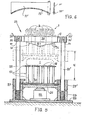
- a complete cutting device 22 is shown in FIG. 5 in a side view and in a partial sectional view. As a basis, this has a frame with a heavy base plate 23 and threaded bushings 24 welded thereon. Guide elements in the form of guide rods 25, 25 'are screwed into it.
- a horizontal machine table 26 provided with guide bushes 27, 27 'is supported by a hydraulic piston / cylinder unit 32. It is a hydraulic telescopic cylinder, which has an advantageously long length when pushed together Working stroke H owns.
- the guide bushes 27, 27 'and the machine table 26 are provided with slide-in guides 28, 28' into which the base plate 20 of the support 17 is inserted.
- the upper ends 29, 29 'of the guide elements or guide rods 25, 25' are conically offset for quick attachment or detachment of cutting elements 30 and with wedge slots 34, 34 ' Mistake. This results in an absolutely safe and uncomplicated positioning and centering of the cutting elements 30, the frame 9 with the fastening tabs 11 and their conical receiving bores 12 snapping exactly into the conical ends 29, 29 'of the guide elements 25, 25'.
- the wedge connections 34, 34 'easily establish a secure connection between the frame 9 and the guide elements 25, 25'.
- the cheese wheel 1 to be cut is placed loosely on the surface parts 18.
- a centering of the cheese wheel is neither necessary nor desirable due to the intended, non-uniform division into pieces of different sizes.
- the pad 17 can be color-coded in the form of circles or ellipses (not shown), which is designed approximately on the model of a shooting target.
- the cheese wheel 1 is pressed through by the cutting elements 30 from below and thus divided in a manner as can be seen, for example, from FIGS. 1 a and 1 b.
- the support 17 projects beyond the upper level of the cutting elements 30, so that the chopped cheese pieces 2 are freely accessible on all sides. This considerably simplifies the operability of the device.
- FIG. 5 and 6 show two embodiments of a blade 10 and 10 'which are essential to the invention.
- 5 is formed in the region of its downward-facing cutting edge 35 in a roof-shaped slope. It has a large number of pointed teeth 36. In contrast to saw teeth, these are not restricted. They are formed between curved tooth flanks and resemble shark teeth.
- the cutting edge 35' is approximately triangular in cross-section and bent in reverse, as the blade according to FIG. 5.
- the cutting pressure is first concentrated in a few areas, whereby for the first time the invention succeeds, surprisingly, in cutting and crusting hard types of cheese cut through.
- the device 22 according to the invention is both compact and uncomplicated. As a result, it is suitable for problem-free use within a sales room and ideally fulfills the task on which the invention is based.
Landscapes
- Life Sciences & Earth Sciences (AREA)
- Forests & Forestry (AREA)
- Engineering & Computer Science (AREA)
- Mechanical Engineering (AREA)
- Animal Husbandry (AREA)
- Environmental Sciences (AREA)
- Dairy Products (AREA)
- Yarns And Mechanical Finishing Of Yarns Or Ropes (AREA)
Abstract
Description
Die Erfindung betrifft ein Verfahren und eine Vorrichtung zum Zerteilen eines Käselaibes oder -blockes, in einzelne, von Schnittkanten begrenzte Stücke, mit einer mechanischen Zerteileinrichtung.The invention relates to a method and a device for dividing a cheese loaf or block, into individual pieces delimited by cut edges, with a mechanical dividing device.
Einrichtungen zum Zerteilen von Käseblöcken sind bekannt. Es handelt sich dabei zumeist um Längs- oder Ouerschneide-- vorrichtungen sowie um Vorrichtungen zum Zerschneiden von runden Käserollen in sektorförmige Teile.Means for chopping blocks of cheese are known. These are mostly slitting or slitting devices as well as devices for cutting round cheese rolls into sector-shaped parts.
Eine bekannte Längs- und Querschneidvorrichtung ist mit senkrecht bzw. waagerecht in einem Rahmen gespannten Schneiddrähten ausgebildet, durch welche der zu zerteilende Käseblock hindurchgeschoben wird. Hierfür ist ein geschlitzter Anschlag vorgesehen, der mit einer an der gegenüberliegenden Seite eines Förderers mit mehreren Schneiddrähten ausgestatteten Querschneidvorrichtung zusammenwirkt. Die Schlitze, die mit den Schneiddrähten fluchten, lassen die Drähte frei durch die Käsestücke hindurchtreten (DE-AS 18 16 008).A known longitudinal and transverse cutting device is formed with cutting wires stretched vertically or horizontally in a frame, through which the block of cheese to be cut is pushed. For this purpose, a slotted stop is provided which interacts with a cross-cutting device equipped with a plurality of cutting wires on the opposite side of a conveyor. The slots, which are aligned with the cutting wires, allow the wires to pass freely through the cheese pieces (DE-AS 18 16 008).
Weiter ist eine Vorrichtung zum Zerschneiden von runden Roquefort-Käserollen in sektorförmige Teile mit Hilfe von Schneidstahldrähten bekannt. Diese besitzt einen runden, in senkrechter Richtung beweglichen Schlitten zur Aufnahme der Käserolle, eine darüber angeordnete Führungs- und Zentriervorrichtung sowie eine oberhalb dieser gelagerte Schneidvorrichtung mit einer Anzahl sich kreuzender Schneiddrähte. Die Käserolle wird während der Aufwärtsbewegung des Schlittens durch die Schneiddrähte hindurchgedrückt. Der Schlitten weist diametral verlaufende, gleichmäßig verteilte Nuten auf, in welche sich die Drähte nach Beendigung der Aufwärtsbewegung des Schlittens einlegen, um sich von den aufgeteilten Käsestücken zu lösen (DE-AS 11 27 657).Furthermore, a device for cutting round Roquefort cheese rolls into sector-shaped parts using cutting steel wires is known. This has a round, carriage movable in the vertical direction for receiving the cheese roll, a guide and centering device arranged above it and a cutting device mounted above it with a number of intersecting cutting wires. The cheese roll is pushed through the cutting wires during the upward movement of the carriage. The slide has diametrically extending, evenly distributed grooves into which the wires lie after the upward movement of the slide has ended in order to detach from the divided pieces of cheese (DE-AS 11 27 657).
Mit Schneiddrähten versehene Zerteileinrichtungen haben den Nachteil, daß sie nur für Weichkäse wie Roquefort oder Schmelzkäseblöcke Verwendung finden können. Weiter ist die Anwendbarkeit bekannter Käsezerteileinrichtungen dadurch begrenzt, daß jeweils nur exakt geformte Käsestücke mit rundem oder eckigem Querschnitt zerteilt werden können. Sie sind gemäß ihrer Bauart und ihrem Verwendungszweck zur Verwendung in Käsefabriken geschaffen und insbesondere zur Serienfertigung gleichartiger für eine Verpackungsmaschine geeigneter Käsestücke geeignet.Cutting devices provided with cutting wires have the disadvantage that they can only be used for soft cheeses such as Roquefort or processed cheese blocks. Furthermore, the applicability of known cheese cutting devices is limited by the fact that only precisely shaped pieces of cheese with a round or angular cross section can be cut. They are designed for use in cheese factories in accordance with their design and intended use and are particularly suitable for series production of similar pieces of cheese suitable for a packaging machine.
Für eine universelle Anwendung, z.B. zur Zerteilung unterschiedlich großer und vielfach harte Krusten aufweisender Käselaibe, z.B. im Verkaufsstand eines Kaufhauses oder Supermarktes, sind solche bekannten Käsezerteilvorrichtungen ungeeignet.Known cheese slicing devices of this type are known for universal use, for example for slicing cheese loaves of different sizes and often having hard crusts, for example in the sales stand of a department store or supermarket unsuitable.
Beim Käseverkauf, insbesondere mittelharter und harter Sorten, wie Gouda, Emmentaler u. ä., kommt es darauf an, den Lagervorrat in unzerteilten Laibern vorrätig zu halten, wobei der unangeschnittene Käse infolge seiner schützenden Kruste sich lange frischhält. Käselaibe werden üblicherweise im Verkaufslokal von Hand zerteilt. Für das zumeist weibliche Verkaufspersonal stellt der Zerteilvorgang großer und harter Käselaibe eine Schwer- bis Schwerstarbeit dar. Nicht selten ergeben sich dabei Handverletzungen oder zum Arbeitsausfall führende Beschwerden durch Überlastung von Handgelenken und/oder Sehnen.When selling cheese, especially medium-hard and hard varieties such as Gouda, Emmentaler u. Ä., it is important to keep the stock in undistributed loafs, the uncut cheese keeps fresh for a long time due to its protective crust. Loaves of cheese are usually cut up by hand in the shop. For the mostly female sales personnel, the process of slicing large and hard cheeses is hard work or hard work. It is not uncommon for hand injuries or complaints that lead to loss of work to result from overloading wrists and / or tendons.
Der Erfindung liegt die Aufgabe zugrunde, ein Verfahren und eine hierauf abgestimmte Vorrichtung zum mechanischen Zerteilen von Käselaiben oder -blöcken anzugeben, womit die bisher bestehenden Schwierigkeiten beim Zerteilen mittelharter oder harter Käselaibe, insbesondere im Verkaufslokal, überwunden werden. Den besonderen Einsatzbedingungen entsprechend soll das Gerät kompakt, einfach und insbesondere unfallsicher in der Bedienung sowie zum Anschnitt mit harten Krusten umgebener Käselaibe geeignet sein. Auch soll die Vorrichtung den strengen Anforderungen an Sauberhaltung und Lebensmittelhygiene entsprechen und darüberhinaus einen möglichst geringen Platz beanspruchen. Ein wichtiger Teil der Aufgabe besteht weiter darin, durch problemloses schnelles Wechseln der Schneideinsätze die Möglichkeit zu schaffen, verschiedene Käsesorten mit unterschiedlichen Schnitteinteilungen zu zerteilen. Insbesondere soll damit die Aufteilung eines Läselaibes in eine Vielzahl von Einzelstücken von unterschiedlicher Größe bzw. unterschiedlichen Formen und Gewichten zu einem verkaufsgerechten Sortiment in einem einzigen Vorgang ermöglicht werden.The invention has for its object to provide a method and a matched device for the mechanical cutting of cheese loaves or blocks, whereby the previously existing difficulties in cutting medium-hard or hard cheese wheels, especially in the shop, are overcome. According to the particular conditions of use, the device should be compact, simple and, in particular, safe to operate and suitable for cutting cheese loaves surrounded by hard crusts. The device should also meet the strict requirements for keeping food clean and hygienic, and should also take up as little space as possible. Another important part of the task is to make it possible to quickly and easily change the cutting inserts to cut different types of cheese with different cuts. In particular, this is intended to enable the division of a loaf of cheese into a large number of individual pieces of different sizes or different shapes and weights to form a sales-oriented assortment in a single operation.
Die Lösung der Aufgabe gelingt mit dem erfindungsgemäßen Verfahren dadurch, daß der Käse von unten frei durch Schneiden einer Zerteileinrichtung hindurchgedrückt wird.The object is achieved with the method according to the invention in that the cheese is freely pressed through from below by cutting a dividing device.
Mit Vorteil wird hierdurch das Verkaufspersonal von der schweren manuellen Zerteilarbeit entlastet und kann sich dem eigentlichen Verkaufsgeschäft widmen. Personalausfall durch Verletzungen oder Überanstrengung von Händen und Armen wird vermieden. Durch Aufteilung des Käselaibes zu einem verkaufsgerechten Sortiment ergibt sich zugleich eine positive Verkaufsförderung beim Kaufpublikum.This advantageously relieves the sales staff of the heavy manual cutting work and can focus on the actual sales business. Loss of personnel due to injuries or overexertion of the hands and arms is avoided. By dividing the cheese loaf into a sales-oriented assortment, there is also positive sales promotion among the buying public.
Unter einem verkaufsgerechten Sortiment von Käsestücken wird eine solche statistische Verteilung in Größe, Gestalt und Gewicht verstanden, welche den Kaufwünschen der Kundschaft optimal entspricht und damit am besten entgegenkommt.A sales-oriented assortment of cheese pieces is understood to mean such a statistical distribution in size, shape and weight that optimally corresponds to the customers' purchase wishes and thus best accommodates.
Eine Ausgestaltung des Verfahrens sieht weiter vor, daß die Käsestücke nach dem Zerteilvorgang mit ihrer Unterlage über die Schneiden hinweg in eine allseits zugängliche Position geschoben werden.One embodiment of the method further provides that the pieces of cheese are pushed with their base over the cutting edges into a position accessible to all after the slicing process.
Mit Vorteil wird hierbei das Abräumen der geschnittenen Käsestücke erleichtert. Weiterhin ist die Maßnahme geeignet, dem kaufenden Publikum den Zerteilvorgang eines Käselaibes in anregender Weise sichtbar zu machen und damit die Kauflust anzuregen.The clearing of the cut pieces of cheese is advantageously facilitated here. The measure is also suitable for making the chopping process of a cheese loaf visible to the buying public and thus stimulating the desire to buy.
Um auch bei sehr harten Käsesorten, wie beispielsweise Emmentaler, mit entsprechend harter Kruste ein Eindringen der Schneiden ohne Überlastung zu ermöglichen, sieht eine weitere Ausgestaltung des Verfahrens vor, daß der Käselaib, die Schneiden oder beide vor Beginn des Zerteilungsvorganges mit einem flüssigen Zerteilungshilfsmittel, vorzugsweise Wassersprühnebel, besprüht werden.In order to allow the cutting edges to penetrate without overloading even with very hard cheeses, such as Emmental cheese, for example, with a correspondingly hard crust, a further embodiment of the method provides that the cheese loaf, the cutting edges, or both, preferably with a liquid cutting aid before the beginning of the dividing process Water spray to be sprayed.
Eine Vorrichtung zum Zerteilen eines Käselaibes oder -blockes in einzelne, von Schnittkanten begrenzte Stücke mit einer mechanischen Zerteileinrichtung, insbesondere zur Durchführung des Verfahrens ist dadurch gekennzeichnet, daß die Schneidelemente innerhalb eines starren Rahmens in parallelen, zum Rahmen senkrechten Ebenen angeordnete messerartige Klingen sind und daß die Auflage den Käsestücken in Form, Abmessung und Anordnung entsprechende Flächenteile mit dazwischenliegenden Schlitzen aufweist, wobei die Flächenteile durch Stützelemente im Abstand mit einer zur horizontalen Auflagefläche vorzugsweise parallelen Grundplatte verbunden sind.A device for dividing a cheese loaf or block into individual pieces delimited by cut edges with a mechanical dividing device, in particular for carrying out the method, is characterized in that the cutting elements within a rigid frame are knife-like blades arranged in parallel planes perpendicular to the frame, and in that the edition of the Pieces of cheese in shape, dimension and arrangement have corresponding surface parts with slots in between, the surface parts being connected by support elements at a distance to a base plate which is preferably parallel to the horizontal support surface.
Damit wird erstmals mit Vorteil das mechanische Zerteilen harter, von Kruste umgebener Käselaibe möglich gemacht. Mit Vorteil wird durch diese Anordnung der Flächenteile auf Stützelementen erreicht, daß die Käsestücke nach dem Zerteilvorgang bis über die Schneidelemente in eine freie Lage gehoben werden können. Weiterhin hat die Anordnung den Vorteil, daß Käseabrieb, wie Krümel, nicht in den Schlitzen liegen bleiben, wie dies bei bekannten Zerteileinrichtungen der Fall ist. Dadurch wird die Sauberhaltung der Vorrichtung erleichtert und dem Gebot der bei Lebensmitteln unerläßlichen Sauberkeit mühelos Rechnung getragen.This makes it possible for the first time to mechanically break up hard cheeses surrounded by crusts. This arrangement of the surface parts on support elements advantageously means that the pieces of cheese can be lifted into a free position after the slicing process, up to and beyond the cutting elements. Furthermore, the arrangement has the advantage that cheese chips, such as crumbs, do not remain in the slots, as is the case with known slicing devices. This makes it easier to keep the device clean and effortlessly takes into account the requirement of cleanliness, which is essential for food.
Weiterhin weist die Vorrichtung eine Fußplatte mit starren, vertikalen Führungselementen auf, in denen ein vertikal antreibbarer, horizontaler Maschinentisch geführt ist, der die Auflage mit ihrer Grundplatte auswechselbar aufnimmt. Am oberen Ende der Führungen ist der Rahmen mit den Schneidelementen schnell auswechselbar befestigt. Die Grundplatte ist im Maschinentisch mittels schubladenartiger Einschübe ebenfalls schnell auswechselbar eingesetzt. Mit Vorteil wird durch die unkomplizierte schnelle Auswechselbarkeit von Auflage und Schneidelementen eine leichte Säuberung dieser Teile ermöglicht und zugleich die Forderung nach problemloser Anpassung der Vorrichtung an unterschiedliche Schnitteinteilungen bei verschiedenen Käselaiben in optimaler Weise erfüllt.Furthermore, the device has a base plate with rigid, vertical guide elements, in which a vertically drivable, horizontal machine table is guided, which interchangeably receives the support with its base plate. At the upper end of the guides, the frame with the cutting elements can be quickly replaced. The base plate can also be quickly replaced in the machine table using drawer-like inserts. Advantageously, the uncomplicated, quick interchangeability of the support and cutting elements enables these parts to be easily cleaned and, at the same time, optimally fulfills the requirement for the device to be easily adapted to different cut divisions in different cheese wheels.
Um dabei eine besonders einfache und rasche Auswechselung der Schneidelemente zu ermöglichen, ist mit einer weiteren Ausgestaltung der Vorrichtung vorgesehen, daß der Rahmen mit den Schneidelementen in konischen Rezessen der oberen Führungsenden mittels konischen Bohrungen aufgesetzt und mit Schnellbefestigungselementen, z.B. mit Keilen festgesetzt ist.In order to enable a particularly simple and quick replacement of the cutting elements, a further embodiment of the device provides that the frame with the cutting elements is placed in conical recesses of the upper guide ends by means of conical bores and with quick fastening elements, e.g. is fixed with wedges.
Die Erfindung wird in Zeichnungen in einer bevorzugten Ausführungsform gezeigt, wobei aus den Zeichnungen weitere vorteilhafte Einzelheiten der Erfindung entnehmbar sind.The invention is shown in drawings in a preferred embodiment, further advantageous details of the invention being apparent from the drawings.
Die Zeichnungen zeigen im einzelnen:
- Fig. la einen erfindungsgemäß in Stücke zerteilten, ursprünglich annähernd runden Käselaib in Draufsicht,
- Fig. lb einen erfindungsgemäß in Stücke zerteilten länglichen Käselaib, ebenfalls in Draufsicht,
- Fig. 2 eine Draufsicht auf Schneidelemente in einer Anordnung innerhalb-eines starren Rahmens,
- Fig. 3 eine Draufsicht auf eine Auflagefäche mit Flächenteilen und dazwischenliegenden Schlitzen,
- Fig. 4 eine Seitenansicht der Auflagefläche gemäß Fig. 3,
- Fig. 5 eine Seitenansicht der kompletten Vorrichtung, teilweise im Schnitt, mit abgesenkter Auflagefläche (durchgezogene Zeichnungslinien) bzw. mit der Arbeitsfläche in ihrer oberen Endstellung (gestrichelte Linien),
- Fig. 6 eine insbesondere für harte Käsesorten mit Kruste geeignete Ausbildung einer Schneidklinge, in Ansicht und geschnitten.
- FIG. 1 a, in plan view, a cheese loaf originally cut into pieces and originally approximately round,
- FIG. 1b shows an elongated cheese loaf cut into pieces according to the invention, likewise in plan view,
- 2 is a plan view of cutting elements in an arrangement within a rigid frame,
- 3 is a plan view of a support surface with surface parts and slots in between,
- 4 is a side view of the support surface according to FIG. 3,
- 5 is a side view of the complete device, partly in section, with the support surface lowered (solid drawing lines) or with the work surface in its upper end position (dashed lines),
- Fig. 6 is a particularly suitable for hard cheeses with crust formation of a cutting blade, in view and cut.
Fig. la zeigt einen in Einzelstücke 2 zerteilten Käselaib 1. Dabei sind die Schnittlinien 7 so gelegt, daß sich zunächst zwei Hälften 3, 3' des ursprünglich annähernd runden Käselaibes 1 ergeben. Weiter ist aus jeder dieser Hälften 3, 3' je ein rechteckiges Mittelstück 4, 4' herausgeschnitten. Die umliegenden-Randpartien 5 sind durch von den Mittelstücken 4, 4' zum Rand 8 verlaufende Schnittlinien 7 in sektorförmige Stücke 6 zerteilt.Fig. La shows a
Die in Fig. la beispielhaft gezeigte Zerteilungsform des Käselaibes 1 ergibt 21 Einzelstücke 2, die untereinander jeweils unterschiedliche Größe, unterschiedliche Gestalt und unterschiedliches Gewicht aufweisen. Hierdurch erhält man ein verkaufsfähiges Sortiment von Einzelstücken 2, das den durch Erfahrungen ermittelten Kaufgepflogenheiten der Kundschaft weitestgehend angepaßt ist. Sollte es darüber hinaus erforderlich sein, einzelne dieser Stücke 2 beim Verkauf noch weiter zu unterteilen, so stellt dies für das Verkaufspersonal keine schwierige oder zeitraubende Anforderung mehr dar. Wesentlich bei der gezeigten Art der aufteilung ist es auch, daß jedes Einzelstück zwei vorzugsweise unterschiedlich lange und gerade Schnittkanten aufweist. Dies ist deshalb wichtig, um beim Hausaufschnitt entweder unterschiedlich große Scheiben abschneiden oder das Käsestück mit dem Käsehobel bearbeiten zu können.The example of the
Fig. lb zeigt eine andere, im Prinzip jedoch ähnlich Art der Zerteilung eines länglichen Käselaibes 1 in unterschiedliche Einzelstücke 2. Auch hierbei ist es zweckmäßig, den Käselaib 1- in zwei Hälften 3, 3' zu zerteilen. Weil es sich um eine andere Käsesorte und einen anders geformten Käselaib 1- handelt, sind im gezeigten Beispiel der Fig. lb die Schnittlinien 7 im wesentlichen so angeordnet, daß sich eine größere Anzahl eckiger Einzelstücke 2' ergibt, von denen einige annähernd quadratisch, andere schmal und lang sind. Eine Schnittlinie 7" ist schräg zur Längsrichtung des Käselaibes 1' gelegt, um damit vier schiefwinklige Eckstücke 2" auszuschneiden.Fig. Lb shows another, but in principle similar way of dividing an
Die unterschiedliche Schnittführung bei verschieden geformten Käselaiben 1, l' und insbesondere unterschiedlichen Käsesorten ist ein wesentlicher Vorteil des erfindungsgemäßen Verfahrens bzw. der entsprechenden Vorrichtung. Damit wird erstmals eine mechanische Zerteilung mittelharter und harter Käselaibe durch eine mechanische Zerteileinrichtung im Verkaufsraum ermöglicht.Äsesorten different cut at different shaped
Als Vorteile ergeben sich dadurch eine Entlastung des Verkaufspersonals von schwerer körperlicher Arbeit, eine Freisetzung von Arbeitskräften für das eigentliche Verkaufsgeschehen sowie ein für die Käuferschaft interessanter, zu einem Verkaufsanreiz führender Anblick bei der mechanischen Zerteilung von Käselaiben.This has the advantages of relieving the sales staff of hard physical work, releasing workers for the actual sales process and a sight that is interesting for the buyers and leads to a sales incentive in the mechanical cutting of cheese wheels.
Fig. 2 zeigt in Draufsicht ein Schneidelement 30. In einem Rahmen 9 sind messerartige Klingen 10 angeordnet und zu einem Netz von Schnittlinien vereinigt. Der Rahmen 9 ist von starrer Konstruktion z.B. aus kastenformen Stahl-Hohlprofilen zusammengeschweißt. Daran sind ebenfalls durch Schweißnähte Befestigüngslaschen 11, 11' befestigt und mit konischen Rezessen 12, 12' in Form von kegelförmigen Aufnahmebohrungen versehen. Die Anordnung der Klingen 10 bildet entsprechend der Aufschnittsform des Käses, beispielsweise wie in Fig. la gezeigt, zwei mittlere Rechtecke 13, 13. Von dort verlaufen Klingen 14 senkrecht zu den Rechteckseiten und Klingen 15, 15' strahlenförmig nach außen. Weitere Klingen 15" sind parallel zur Mittelachse angeordnet. An den Knotenpunkten 16 sind die Klingen 10', 14, 15, 15' und 15" jeweils miteinander metallisch verbunden. Vorzugsweise ist diese Verbindung im Hartlötverfahren und insbesondere im Schutzgas-Hartlötverfahren ausgeführt. Dadurch erhalten diese Verbindungen eine Festigkeit, die annähernd derjenigen des Klingenstahles entspricht. Dies ist erforderlich, um den zu einem Schneidelement 30 vereinigten Klingen die notwendige Festigkeit im Gesamtverbund zu verleihen, die beim Durchtrennen eines Käselaibes 1, 1' mit harter Kruste erforderlich ist.2 shows a top view of a cutting
Eine auf die Anordnung des Schneidelementes 30 in Fig. 2 abgestimmte Auflage 17 ist in den Fig. 3 und 4 dargestellt. Fig. 3 zeigt eine Draufsicht, während Fig. 4 eine Seitenansicht, z. T. im Schnitt, entlang einer Schnittlinie IV-IV in Fig. 3 zeigt. Auf einer Grundplatte 20 sind die einzelnen Flächenteile 18 mittels Stützen 19 im Abstand befestigt. Die Grundplatte 20 ist so starr ausgeführt, daß sie den beim Schneidvorgang auf sie einwirkenden Kräften ohne erkennbare Durchbiegung widersteht. Sie ist beispielsweise eine Stahlplatte von ausreichender Stabilität. Die Grundplatte 20 kann auch aus faserverstärktem Kunststoff gefertigt und an der Unterseite zur Stabilisierung vorzugsweise stark verrippt sein. Es kann sich auch um eine in Sandwich-Bauart gefertigte starre Platte handeln. Auf jeden Fall muß sie sowohl außerordentlich stabil als auch relativ leicht sein. Die Stützelemente bzw. Stützen 19 sind z.B. dünnwandige Stahlrohre und durch Schweißung sowohl mit der Grundplatte 20 als auch mit den Flächenteilen 18 verbunden. Abweichend hiervon können sowohl Grundplatte, Stützen und Flächenteile aus Kunststoff oder Plexiglas gefertigt sein.A
In Fig. 4 sind Flächenteile 18 mit Beschichtungen 21, beispielsweise mit Teflon, dargestellt. Diese sind für Bedürfnisse der Lebensmittelhygiene besonders zweckmäßig. Zwischen den einzelnen Flächenteilen 18, 18' ergeben sich Schlitze 33, durch die die Klingen 10 des Schneidelementes 30 beim Zerteilvorgang frei hindurchtreten können. Eine komplette Zerteilvorrichtung 22 zeigt Fig. 5 in Seitenansicht, sowie in teilweiser Schnittdarstellung. Diese besitzt als Basis ein Gestell mit einer schweren Fußplatte 23 und darauf angeschweißte Gewindebuchsen 24. Darin sind Führungselemente in Form von Führungsstangen 25, 25' eingeschraubt. Ein mit Führungsbuchsen 27, 27' versehener horizontaler Maschinentisch 26 ist von einer hydraulischen Kolben/Zylindereinheit 32 unterstützt. Es handelt sich dabei um einen hydraulischen Teleskopzylinder, welcher im zusammengeschobenen Zustand einen vorteilhaft langen Arbeitshub H besitzt. Die Führungsbuchsen 27, 27' bzw. der Maschinentisch 26 sind mit Einschubführungen 28, 28' versehen, in welche die Grundplatte 20 der Auflage 17 eingeschoben ist. Damit ergibt sich der Vorteil einer leichten und völlig unkomplizierten Auswechselbarkeit dieser Auflage 17. Die oberen Enden 29, 29' der Führungselemente bzw. Führungsstangen 25, 25' sind zur schnellen Befestigung bzw. Lösung von Schneidelementen 30 konisch abgesetzt und mit Keilschlitzen 34, 34' versehen. Hierdurch ergibt sich eine absolut sichere und unkomplizierte Positionierung und Zentrierung der Schneidelemente 30, wobei der Rahmen 9 mit den Befestigungslaschen 11 und deren konischen Aufnahmebohrungen 12 exakt in die konischen Enden 29, 29' der Führungselemente 25, 25' einrastet. Durch die Keilverbindungen 34, 34' wird in Sekundenschnelle mühelos eine sichere Verbindung zwischen dem Rahmen 9 und den Führungselementen 25, 25' hergestellt.4 shows
In der unteren, mit ausgezogenen Zeichenlinien dargestellten Position des horizontalen Maschinentisches 26 sowie der Auflage 17 ist der zu zerschneidende Käselaib 1 auf die Flächenteile 18 lose aufgelegt. Eine Zentrierung des Käselaibes ist dabei infolge der beabsichtigten, ungleichförmigen Zerteilung in unterschiedlich große Stücke weder erforderlich noch erwünscht. Um jedoch eine Orientierungshilfe für das Personal zu geben, kann die Auflage 17 eine Farbkennzeichnung in Form von Kreisen oder Ellipsen (nicht dargestellt) aufweisen, die etwa nach dem Vorbild einer Schießscheibe ausgebildet ist.In the lower position of the horizontal machine table 26 and the
In der mit unterbrochenen Linien gestrichelt dargestellten oberen Position ist der Käselaib 1 durch die Schneidelemente 30 von unten hindurchgedrückt und damit in einer Weise zerteilt, wie dies beispielsweise aus den Fig. la und lb hervorgeht. Dabei ragt die Auflage 17 über die obere Ebene der Schneidelemente 30 hinaus, so daß die zerteilten Käsestücke 2 allseits frei zugänglich sind. Hierdurch wird die Bedienbarkeit der Vorrichtung erheblich erleichtert.In the upper position shown in broken lines with dashed lines, the
Zwei erfindungswesentliche Ausgestaltungen einer Klinge 10 bzw. 10' zeigen Fig. 5 und 6.5 and 6 show two embodiments of a
Die Klinge gemäß Fig. 5 ist im Bereich ihrer nach unten weisenden Schneide 35 in einer dachförmigen Schräge ausgebildet. Sie weist eine Vielzahl spitzer Zähne 36 auf. Diese sind im Gegensatz zu Sägezähnen nicht geschränkt. Sie sind zwischen bogenförmig zusammenlaufenden Zahnflanken ausgebildet und ähneln Haifischzähnen.5 is formed in the region of its downward-facing
Bei der Klinge 10' gemäß Fig. 6 ist die Schneide 35' querschnittlich etwa dreieckig ausgebildet und umgekehrt gebogen, wie die Klinge gemäß Fig. 5.In the blade 10 'according to FIG. 6, the cutting edge 35' is approximately triangular in cross-section and bent in reverse, as the blade according to FIG. 5.
Mit der besonderen Form und Ausbildung der Klingen 10 bzw. 10' wird erreicht, daß im Gegensatz zu einer geradlinigen Messerschneide zunächst der Schneiddruck auf wenige Bereiche konzentriert wird, wodurch es mit der Erfindung erstmalig in überraschender Weise gelingt, auch Krusten harter Käsesorten anzuschneiden und zu durchtrennen.With the special shape and design of the
Es hat sich nämlich herausgestellt, daß die zum Zerteilen eines harten Käselaibes notwendigen Schneidkräfte durch gemäß Fig. 5 und 6 ausgebildete Schneiden mit einem Bruchteil derjenigen Kräfte aufgebracht werden, die mit glatten messerartigen Schneiden aufgewendet werden müßten.It has been found that the cutting forces required to cut a hard cheese wheel are applied by cutting edges designed according to FIGS. 5 and 6 with a fraction of the forces which would have to be used with smooth knife-like cutting edges.
Wie Fig. 5 zeigt, ist die erfindungsgemäße Vorrichtung 22 sowohl kompakt als auch unkompliziert. Sie eignet sich infolgedessen zur problemlosen Verwendung innerhalb eines Verkaufsraumes, und erfüllt in idealer Weise die der Erfindung zugrundeliegende Aufgabenstellung.As FIG. 5 shows, the
Claims (8)
dadurch gekennzeichnet, daß der Käse von unten frei durch Schneiden einer Zerteileinrichtung hindurchgedrückt wird.1. Method for dividing a cheese loaf or block into individual pieces delimited by cut edges, with a mechanical dividing device,
characterized in that the cheese is pressed freely from below by cutting a slicer.
dadurch gekennzeichnet, daß
die Käsestücke nach dem Zerteilvorgang mit ihrer Unterlage über die Schneiden hinweg in eine allseits zugängliche Position gehoben werden.2. The method according to claim 1,
characterized in that
the pieces of cheese are lifted with their base over the cutting edges into a position accessible to all after the cutting process.
dadurch gekennzeichnet, daß
der Käselaib, die Schneiden oder beide vor Beginn des Zerteilungsvorganges mit einem flüssigen Zerteilungshilfsmittel, vorzugsweise Wassersprühnebel, besprüht werden.3. The method according to claim 1 or 2,
characterized in that
the cheese loaf, the cutting edges or both are sprayed with a liquid cutting aid, preferably water spray, before the start of the cutting process.
die Schneidelemente (30) innerhalb eines starren Rahmens (9) in parallelen, zum Rahmen (9) senkrechten Ebenen angeordnete messerartige Klingen (10) sind und daß die Auflage (17) den Käsestücken (2,4,6) in Form, Abmessung und Anordnung entsprechende Flächenteile (18) mit dazwischenliegenden Schlitzen (33) aufweist, wobei die Flächenteile (18) durch Stützelemente (19) im Abstand mit einer zur horizontalen Auflagefläche (17) vorzugsweise parallelen Grundplatte (20) verbunden sind.4. Device for dividing a cheese loaf or block into individual pieces delimited by cut edges, with a mechanical dividing device, in particular for carrying out the method according to one or more of claims 1 to 3, characterized in that
the cutting elements (30) within a rigid frame (9) Knife-like blades (10) arranged in parallel planes perpendicular to the frame (9) and that the support (17) corresponds to the pieces of cheese (2, 4, 6) in shape, size and arrangement with corresponding surface parts (18) with slots (33) in between. The surface parts (18) are connected by support elements (19) at a distance to a base plate (20) which is preferably parallel to the horizontal support surface (17).
dadurch gekennzeichnet, daß
sie (22) eine Fußplatte (23) mit starren, vertikalen Führungselementen (25) aufweist, in denen ein vertikal antreibbarer, horizontaler Maschinentisch (26) geführt ist, der die Auflage (17) mit ihrer Grundplatte (20) auswechselbar aufnimmt, und daß am oberen Ende (29) der Führungselemente (25) der Rahmen (9) mit den Schneidelementen (10,30) auswechselbar befestigt ist.5. The device according to claim 4,
characterized in that
it (22) has a base plate (23) with rigid, vertical guide elements (25) in which a vertically drivable, horizontal machine table (26) is guided, which interchangeably receives the support (17) with its base plate (20), and that at the upper end (29) of the guide elements (25) the frame (9) with the cutting elements (10, 30) is exchangeably fastened.
dadurch gekennzeichnet, daß
die Grundplatte (20) im Maschinentisch (26) mittels schubladenartiger Einschübe (28) auswechselbar eingesetzt ist und/ oder daß der Rahmen (9) mit den Schneidelementen (10,30) an den oberen Enden (29) der Führungselemente (25) mittels konischer Hülsen (12) aufgesetzt und mit Schnellbefestigungselementen, z.B. Keilen (31,34), festgesetzt ist.6. The device according to claim 4 or 5,
characterized in that
the base plate (20) is interchangeably inserted in the machine table (26) by means of drawer-like inserts (28) and / or that the frame (9) with the cutting elements (10, 30) at the upper ends (29) of the guide elements (25) is conical Sleeves (12) placed and fastened with quick fasteners, such as wedges (31,34).
dadurch gekennzeichnet, daß
als Antrieb für den Maschinentisch (26) eine vorzugsweise hydraulische Kolben/Zylindereinheit (32), vorzugsweise eine mehrfach teleskopierende Einheit, vorgesehen ist.7. The device according to claim 4 or one of the following,
characterized in that
a preferably hydraulic piston / cylinder unit (32), preferably a multiple telescopic unit, is provided as the drive for the machine table (26).
dadurch gekennzeichnet, daß
die Höhe der Klinge (10 bzw. 10') zur Mitte hin zu-bzw. abnimmt.8. Device according to one of the preceding claims,
characterized in that
the height of the blade (10 or 10 ') towards or towards the center. decreases.
Priority Applications (1)
| Application Number | Priority Date | Filing Date | Title |
|---|---|---|---|
| AT84108799T ATE37817T1 (en) | 1983-11-03 | 1984-07-25 | DEVICE FOR MECHANICALLY CUTTING LOAF OR BLOCKS OF CHEESE. |
Applications Claiming Priority (2)
| Application Number | Priority Date | Filing Date | Title |
|---|---|---|---|
| DE3339801 | 1983-11-03 | ||
| DE19833339801 DE3339801A1 (en) | 1983-11-03 | 1983-11-03 | METHOD, OPERATING METHOD AND DEVICE FOR MECHANICALLY DIVIDING CHEESE WHEELS OR BLOCKS |
Publications (2)
| Publication Number | Publication Date |
|---|---|
| EP0144513A1 true EP0144513A1 (en) | 1985-06-19 |
| EP0144513B1 EP0144513B1 (en) | 1988-10-12 |
Family
ID=6213385
Family Applications (1)
| Application Number | Title | Priority Date | Filing Date |
|---|---|---|---|
| EP84108799A Expired EP0144513B1 (en) | 1983-11-03 | 1984-07-25 | Device for the mechanical dividing of cheese loafs or blocks |
Country Status (7)
| Country | Link |
|---|---|
| US (1) | US4608896A (en) |
| EP (1) | EP0144513B1 (en) |
| AT (1) | ATE37817T1 (en) |
| AU (1) | AU563912B2 (en) |
| CA (1) | CA1231076A (en) |
| DE (2) | DE3339801A1 (en) |
| ZA (1) | ZA847820B (en) |
Cited By (6)
| Publication number | Priority date | Publication date | Assignee | Title |
|---|---|---|---|---|
| DE3543350A1 (en) * | 1985-12-07 | 1987-06-11 | Rheinische Werkzeug & Metallf | Slicing machine for producing cold cuts, especially cheese slicing machine |
| FR2651168A1 (en) * | 1989-08-22 | 1991-03-01 | Reybier Fromageries | PROCESS FOR CUTTING A CUTTOP CHEESE GRINDER AND OBTAINED PORTIONS |
| DE9112661U1 (en) * | 1991-10-11 | 1991-12-05 | Dott, Gerd-Dieter, 5400 Koblenz | Device for cutting a hard or semi-hard cheese wheel |
| EP0587524A1 (en) * | 1992-07-28 | 1994-03-16 | Mario Lardi | Cutting device for tarts |
| WO1995030518A1 (en) * | 1994-05-05 | 1995-11-16 | Unilever Plc | Method of dividing a food block into portions |
| DE29700852U1 (en) * | 1997-01-18 | 1997-02-27 | Dott, Gerd-Dieter, 56566 Neuwied | Device for cutting a loaf of cheese |
Families Citing this family (11)
| Publication number | Priority date | Publication date | Assignee | Title |
|---|---|---|---|---|
| US4955271A (en) * | 1989-10-31 | 1990-09-11 | Boutin Lester Paige L Z | Lettuce and vegetable cutting device |
| US5483856A (en) * | 1992-05-05 | 1996-01-16 | Marquip, Inc. | Apparatus and method for slitting corrugated paperboard boxes |
| US5448873A (en) * | 1993-02-05 | 1995-09-12 | New Holland North America, Inc. | Net knife for round baler |
| US5431078A (en) * | 1994-02-22 | 1995-07-11 | Good Idea! Inc. | Apparatus for slicing a food article |
| DE29808051U1 (en) * | 1998-03-27 | 1999-07-29 | Kiesel, Alfred, 47259 Duisburg | Mechanical cheese scoop |
| US20030221535A1 (en) * | 2002-04-01 | 2003-12-04 | Sargento Foods Inc. | Structure and method for cutting slabs of natural cheeses into shape (s) via cutting blades of a pattern such that the shape (s) are tessellated or nested |
| US7530303B2 (en) * | 2004-03-30 | 2009-05-12 | Kraft Foods Global Brands Llc | Cheese wheel cutter |
| US7540221B1 (en) * | 2005-05-24 | 2009-06-02 | Marchant Schmidt, Inc. | Exact weight cutting and destacking system for food products |
| US20080178750A1 (en) * | 2007-01-25 | 2008-07-31 | Rogers Gary J | Method and apparatus for cutting the top off an immature coconut |
| US20100175568A1 (en) * | 2009-01-12 | 2010-07-15 | Little Caesar Enterprises, Inc. | Method And Apparatus For Cutting Food Product |
| US8276490B2 (en) | 2010-01-29 | 2012-10-02 | Marchant Schmidt, Inc. | Exact weight cutting system for food products |
Citations (7)
| Publication number | Priority date | Publication date | Assignee | Title |
|---|---|---|---|---|
| GB184212A (en) * | 1921-03-08 | 1922-08-08 | Creamery Package Mfg Co | Butter cutter |
| US1768693A (en) * | 1926-10-04 | 1930-07-01 | Kaskouras Thomas | Butter-cutting machine |
| US2561274A (en) * | 1947-11-28 | 1951-07-17 | Armour & Co | Cutting apparatus |
| DE1127657B (en) * | 1959-07-10 | 1962-04-12 | Caves & Des Producteurs Reunis | Device for cutting round rolls of cheese into sector-shaped parts |
| GB941941A (en) * | 1961-08-08 | 1963-11-20 | Wright & Son Dorchester Ltd G | Improvements in or relating to cheese cutting machines |
| GB957169A (en) * | 1959-10-13 | 1964-05-06 | J W Flower & Company Engineers | Apparatus for cutting cheese wheels into segments |
| DE2903335B1 (en) * | 1979-01-29 | 1980-02-07 | Horst Groneweg | Method and device for oiling the knife of a bread slicer |
Family Cites Families (5)
| Publication number | Priority date | Publication date | Assignee | Title |
|---|---|---|---|---|
| US884845A (en) * | 1907-10-22 | 1908-04-14 | Ellis T Nicklin | Commodity-dividing apparatus. |
| US2346282A (en) * | 1942-03-06 | 1944-04-11 | George W Watts | Vegetable strip cutter |
| US2383814A (en) * | 1943-09-24 | 1945-08-28 | De Soto E Richardson | Apple slicer |
| US3077215A (en) * | 1960-03-28 | 1963-02-12 | William E Kentor | Meat cubing machine |
| US4072075A (en) * | 1976-04-28 | 1978-02-07 | Norio Ezaki | Cake cutter |
-
1983
- 1983-11-03 DE DE19833339801 patent/DE3339801A1/en not_active Withdrawn
-
1984
- 1984-07-25 EP EP84108799A patent/EP0144513B1/en not_active Expired
- 1984-07-25 AT AT84108799T patent/ATE37817T1/en not_active IP Right Cessation
- 1984-07-25 DE DE8484108799T patent/DE3474528D1/en not_active Expired
- 1984-10-05 ZA ZA847820A patent/ZA847820B/en unknown
- 1984-10-05 AU AU33869/84A patent/AU563912B2/en not_active Ceased
- 1984-10-17 CA CA000465693A patent/CA1231076A/en not_active Expired
- 1984-11-01 US US06/667,013 patent/US4608896A/en not_active Expired - Lifetime
Patent Citations (7)
| Publication number | Priority date | Publication date | Assignee | Title |
|---|---|---|---|---|
| GB184212A (en) * | 1921-03-08 | 1922-08-08 | Creamery Package Mfg Co | Butter cutter |
| US1768693A (en) * | 1926-10-04 | 1930-07-01 | Kaskouras Thomas | Butter-cutting machine |
| US2561274A (en) * | 1947-11-28 | 1951-07-17 | Armour & Co | Cutting apparatus |
| DE1127657B (en) * | 1959-07-10 | 1962-04-12 | Caves & Des Producteurs Reunis | Device for cutting round rolls of cheese into sector-shaped parts |
| GB957169A (en) * | 1959-10-13 | 1964-05-06 | J W Flower & Company Engineers | Apparatus for cutting cheese wheels into segments |
| GB941941A (en) * | 1961-08-08 | 1963-11-20 | Wright & Son Dorchester Ltd G | Improvements in or relating to cheese cutting machines |
| DE2903335B1 (en) * | 1979-01-29 | 1980-02-07 | Horst Groneweg | Method and device for oiling the knife of a bread slicer |
Cited By (9)
| Publication number | Priority date | Publication date | Assignee | Title |
|---|---|---|---|---|
| DE3543350A1 (en) * | 1985-12-07 | 1987-06-11 | Rheinische Werkzeug & Metallf | Slicing machine for producing cold cuts, especially cheese slicing machine |
| FR2651168A1 (en) * | 1989-08-22 | 1991-03-01 | Reybier Fromageries | PROCESS FOR CUTTING A CUTTOP CHEESE GRINDER AND OBTAINED PORTIONS |
| EP0419372A1 (en) * | 1989-08-22 | 1991-03-27 | Fromageries Reybier | Method for portioning cheese and portions obtained |
| DE9112661U1 (en) * | 1991-10-11 | 1991-12-05 | Dott, Gerd-Dieter, 5400 Koblenz | Device for cutting a hard or semi-hard cheese wheel |
| EP0536507A2 (en) * | 1991-10-11 | 1993-04-14 | Burkhard Topp | Device for splitting a whole cheese |
| EP0536507A3 (en) * | 1991-10-11 | 1993-09-08 | Burkhard Topp | Device for splitting a whole cheese |
| EP0587524A1 (en) * | 1992-07-28 | 1994-03-16 | Mario Lardi | Cutting device for tarts |
| WO1995030518A1 (en) * | 1994-05-05 | 1995-11-16 | Unilever Plc | Method of dividing a food block into portions |
| DE29700852U1 (en) * | 1997-01-18 | 1997-02-27 | Dott, Gerd-Dieter, 56566 Neuwied | Device for cutting a loaf of cheese |
Also Published As
| Publication number | Publication date |
|---|---|
| DE3339801A1 (en) | 1985-05-15 |
| AU3386984A (en) | 1986-05-08 |
| CA1231076A (en) | 1988-01-05 |
| ZA847820B (en) | 1985-06-26 |
| AU563912B2 (en) | 1987-07-23 |
| ATE37817T1 (en) | 1988-10-15 |
| US4608896A (en) | 1986-09-02 |
| EP0144513B1 (en) | 1988-10-12 |
| DE3474528D1 (en) | 1988-11-17 |
Similar Documents
| Publication | Publication Date | Title |
|---|---|---|
| EP0144513B1 (en) | Device for the mechanical dividing of cheese loafs or blocks | |
| DE3500495C2 (en) | ||
| DE2922739C2 (en) | Fruit grater | |
| DE19614125C2 (en) | Sheet cake cutting machine | |
| DE534581C (en) | Bread knife | |
| DE435694C (en) | Cutting device for onions, vegetables, etc. | |
| DE102005035343A1 (en) | Machine cutting soft foods such as tomatoes, cucumbers, soft cheese and mozzarella, includes closely-adjacent blades held parallel and upright in frame | |
| DE8331564U1 (en) | DEVICE FOR DIVIDING A CHEESE WHEEL OR BLOCK INTO INDIVIDUAL PIECES LIMITED BY CUTTING EDGES | |
| DE3604477A1 (en) | Device for cutting up raw food | |
| DE484595C (en) | Device for cutting cakes into wedge-shaped parts | |
| DE6608205U (en) | FOOD CUTTER. | |
| DE2822633A1 (en) | DEVICE FOR PORTIONING MEAT | |
| DE664477C (en) | Bread slicer | |
| DE1629988A1 (en) | Food slicer | |
| CH667381A5 (en) | Hand-held food slicing tool - has handle with blades forced into slots across shaped food supporting block with hinged connection | |
| DE919087C (en) | Device for preparing meat | |
| DE639471C (en) | Machine for cutting potatoes or the like into schnitzel | |
| DE590101C (en) | Vegetable slicer for smooth, strip and colored cuts | |
| DE102016005740B3 (en) | Apparatus for cutting circular flatbread | |
| DE942709C (en) | Kitchen appliance for multiple purposes | |
| DE456121C (en) | Cutting machine for tubers and other fruits, fruits, vegetables, meat, bacon, bread, etc. like | |
| DE865075C (en) | Dividing device for cheese | |
| DE2051780C3 (en) | Device for cutting tomatoes and the like | |
| DE201815C (en) | ||
| DE512106C (en) | Machine for cutting strips of square and rectangular cross-section for meat salad u. like |
Legal Events
| Date | Code | Title | Description |
|---|---|---|---|
| PUAI | Public reference made under article 153(3) epc to a published international application that has entered the european phase |
Free format text: ORIGINAL CODE: 0009012 |
|
| AK | Designated contracting states |
Designated state(s): AT BE CH DE FR GB IT LI LU NL SE |
|
| 17P | Request for examination filed |
Effective date: 19850509 |
|
| 17Q | First examination report despatched |
Effective date: 19860821 |
|
| GRAA | (expected) grant |
Free format text: ORIGINAL CODE: 0009210 |
|
| AK | Designated contracting states |
Kind code of ref document: B1 Designated state(s): AT BE CH DE FR GB IT LI LU NL SE |
|
| REF | Corresponds to: |
Ref document number: 37817 Country of ref document: AT Date of ref document: 19881015 Kind code of ref document: T |
|
| REF | Corresponds to: |
Ref document number: 3474528 Country of ref document: DE Date of ref document: 19881117 |
|
| ITF | It: translation for a ep patent filed | ||
| ET | Fr: translation filed | ||
| GBT | Gb: translation of ep patent filed (gb section 77(6)(a)/1977) | ||
| PLBE | No opposition filed within time limit |
Free format text: ORIGINAL CODE: 0009261 |
|
| STAA | Information on the status of an ep patent application or granted ep patent |
Free format text: STATUS: NO OPPOSITION FILED WITHIN TIME LIMIT |
|
| 26N | No opposition filed | ||
| ITTA | It: last paid annual fee | ||
| EPTA | Lu: last paid annual fee | ||
| EAL | Se: european patent in force in sweden |
Ref document number: 84108799.2 |
|
| PGFP | Annual fee paid to national office [announced via postgrant information from national office to epo] |
Ref country code: GB Payment date: 19980717 Year of fee payment: 15 |
|
| PG25 | Lapsed in a contracting state [announced via postgrant information from national office to epo] |
Ref country code: GB Free format text: LAPSE BECAUSE OF NON-PAYMENT OF DUE FEES Effective date: 19990725 |
|
| GBPC | Gb: european patent ceased through non-payment of renewal fee |
Effective date: 19990725 |
|
| PGFP | Annual fee paid to national office [announced via postgrant information from national office to epo] |
Ref country code: FR Payment date: 20010822 Year of fee payment: 18 |
|
| PGFP | Annual fee paid to national office [announced via postgrant information from national office to epo] |
Ref country code: SE Payment date: 20010824 Year of fee payment: 18 Ref country code: LU Payment date: 20010824 Year of fee payment: 18 Ref country code: CH Payment date: 20010824 Year of fee payment: 18 Ref country code: BE Payment date: 20010824 Year of fee payment: 18 Ref country code: AT Payment date: 20010824 Year of fee payment: 18 |
|
| PGFP | Annual fee paid to national office [announced via postgrant information from national office to epo] |
Ref country code: NL Payment date: 20010827 Year of fee payment: 18 |
|
| PG25 | Lapsed in a contracting state [announced via postgrant information from national office to epo] |
Ref country code: LU Free format text: LAPSE BECAUSE OF NON-PAYMENT OF DUE FEES Effective date: 20020725 Ref country code: AT Free format text: LAPSE BECAUSE OF NON-PAYMENT OF DUE FEES Effective date: 20020725 |
|
| PG25 | Lapsed in a contracting state [announced via postgrant information from national office to epo] |
Ref country code: SE Free format text: LAPSE BECAUSE OF NON-PAYMENT OF DUE FEES Effective date: 20020726 |
|
| PG25 | Lapsed in a contracting state [announced via postgrant information from national office to epo] |
Ref country code: LI Free format text: LAPSE BECAUSE OF NON-PAYMENT OF DUE FEES Effective date: 20020731 Ref country code: CH Free format text: LAPSE BECAUSE OF NON-PAYMENT OF DUE FEES Effective date: 20020731 Ref country code: BE Free format text: LAPSE BECAUSE OF NON-PAYMENT OF DUE FEES Effective date: 20020731 |
|
| PGFP | Annual fee paid to national office [announced via postgrant information from national office to epo] |
Ref country code: DE Payment date: 20021224 Year of fee payment: 19 |
|
| BERE | Be: lapsed |
Owner name: *TOPP BURKHARD Effective date: 20020731 |
|
| PG25 | Lapsed in a contracting state [announced via postgrant information from national office to epo] |
Ref country code: NL Free format text: LAPSE BECAUSE OF NON-PAYMENT OF DUE FEES Effective date: 20030201 |
|
| EUG | Se: european patent has lapsed | ||
| REG | Reference to a national code |
Ref country code: CH Ref legal event code: PL |
|
| PG25 | Lapsed in a contracting state [announced via postgrant information from national office to epo] |
Ref country code: FR Free format text: LAPSE BECAUSE OF NON-PAYMENT OF DUE FEES Effective date: 20030331 |
|
| NLV4 | Nl: lapsed or anulled due to non-payment of the annual fee |
Effective date: 20030201 |
|
| REG | Reference to a national code |
Ref country code: FR Ref legal event code: ST |
|
| PG25 | Lapsed in a contracting state [announced via postgrant information from national office to epo] |
Ref country code: DE Free format text: LAPSE BECAUSE OF NON-PAYMENT OF DUE FEES Effective date: 20040203 |