EP0144035A1 - Rotationsfallschirm - Google Patents
Rotationsfallschirm Download PDFInfo
- Publication number
- EP0144035A1 EP0144035A1 EP84113945A EP84113945A EP0144035A1 EP 0144035 A1 EP0144035 A1 EP 0144035A1 EP 84113945 A EP84113945 A EP 84113945A EP 84113945 A EP84113945 A EP 84113945A EP 0144035 A1 EP0144035 A1 EP 0144035A1
- Authority
- EP
- European Patent Office
- Prior art keywords
- parachute
- cap
- lines
- load
- suspension
- Prior art date
- Legal status (The legal status is an assumption and is not a legal conclusion. Google has not performed a legal analysis and makes no representation as to the accuracy of the status listed.)
- Ceased
Links
- 239000000725 suspension Substances 0.000 claims description 52
- 238000011084 recovery Methods 0.000 claims description 7
- 229910000831 Steel Inorganic materials 0.000 claims description 2
- 239000010959 steel Substances 0.000 claims description 2
- 230000005540 biological transmission Effects 0.000 description 2
- 230000000694 effects Effects 0.000 description 2
- 238000009958 sewing Methods 0.000 description 2
- 230000002411 adverse Effects 0.000 description 1
- 230000001419 dependent effect Effects 0.000 description 1
- 238000010586 diagram Methods 0.000 description 1
- 238000006073 displacement reaction Methods 0.000 description 1
- 230000002349 favourable effect Effects 0.000 description 1
- 230000005484 gravity Effects 0.000 description 1
- 230000007257 malfunction Effects 0.000 description 1
- 230000002093 peripheral effect Effects 0.000 description 1
- 239000007787 solid Substances 0.000 description 1
- 230000006641 stabilisation Effects 0.000 description 1
- 238000011105 stabilization Methods 0.000 description 1
Images
Classifications
-
- B—PERFORMING OPERATIONS; TRANSPORTING
- B64—AIRCRAFT; AVIATION; COSMONAUTICS
- B64D—EQUIPMENT FOR FITTING IN OR TO AIRCRAFT; FLIGHT SUITS; PARACHUTES; ARRANGEMENT OR MOUNTING OF POWER PLANTS OR PROPULSION TRANSMISSIONS IN AIRCRAFT
- B64D17/00—Parachutes
- B64D17/22—Load suspension
- B64D17/24—Rigging lines
Definitions
- the invention relates to a rotating parachute according to the preamble of the main claim.
- Rotation parachutes as such are known. Parachute systems in which the cap rotates about its own longitudinal axis in the case are referred to as rotating parachutes.
- Rotary parachutes are known, their pendulum angle compared to conventional parachutes systems could be reduced from plus / minus 25 degrees to plus / minus 3 degrees.
- the rotational property of the parachute canopy is achieved by various measures. For example, it is known to arrange the individual paths forming the parachute cap asymmetrically. Another known embodiment provides that openings are provided in the paths of the parachute cap, which bring about a nozzle effect for the air flowing through them, and depending on the arrangement of these openings or the individual paths of the parachute cap there is a rotational effect of the cap as a whole .
- Such a swivel can consist, for example, of a ball bearing, so that, if applicable, torques transmitted from the parachute cap via the suspension lines are not transmitted to the attached load.
- the invention has for its object to provide a rotating parachute with which not only a rotation of the parachute can be reached, but the rotational energy of which can be transmitted directly or indirectly to an attached load almost without delay.
- a rotating parachute is provided with a cap, which is connected to a load carrier via suspension lines, the suspension lines being arranged offset with respect to the central longitudinal axis of the parachute.
- the lines do not run - in an imaginary extension - through the central longitudinal axis of the parachute, but at a distance from this (fictitious) axis.
- the individual suspension lines are arranged in different directions with respect to the direction of rotation of the cap.
- half of the suspension lines are arranged "obliquely” in the later direction of rotation of the cap, while the other half of the suspension lines are attached "obliquely” between the cap and the load carrier in the opposite direction.
- the individual safety lines do not turn up, but that the oblique arrangement of the individual safety lines relative to one another is maintained unchanged.
- each suspension line has at least one crossing point with one or more other suspension lines.
- each suspension line has two crossing points with two other suspension lines.
- the invention also offers an embodiment in which two or more lines extend from a line attachment point on the parachute cap, which are then each attached to a separate line attachment point on the load carrier.
- the individual suspension lines preferably run from their common connection point in different directions to the load carrier.
- the same embodiment can also be designed the other way round, that is to say that more than one safety line runs from a safety line connection point on the load carrier, the individual safety lines then being attached to individual safety line connection points of the parachute cap.
- the individual suspension lines have the same length and are attached to the load carrier at the same distance from the central longitudinal axis of the parachute, the latter is, in the vertical case of the parachute, in a substantially horizontal one Alignment, provided the center of gravity of the load carrier is in the central longitudinal axis of the parachute.
- an embodiment can also be desired in which the load carrier or the load is arranged obliquely in the horizontal case of the parachute.
- an embodiment of a rotating parachute according to the invention is particularly suitable, in which the suspension lines are of different lengths, so that the load carrier or the load is automatically inclined, provided that the individual suspension lines are arranged in the usual manner at the same distance from the central longitudinal axis of the parachute.
- the circumferential distances of the suspension line connection points on the parachute cap are kept the same size in relation to the filled cap state by means of a circumferential line.
- the sections of this tether between the individual suspension line connection points are shorter than the corresponding circumference of the cap edge. This can reliably prevent a web from changing its shape in the case, in particular being pulled together.
- the fall behavior of the parachute when equipped with the pull line described can be kept very constant.
- the invention also provides a complete salvage system consisting of a rotary Parachute of the type described above and a load attached to it.
- the load can be connected directly or indirectly, for example via an intermediate plate, to the parachute cap.
- this can either be arranged such that it is arranged horizontally when the parachute falls vertically, or, as already described above with reference to the load carrier, is at an angle.
- a non-rotatable but bendable connection to the load is then preferably arranged on the intermediate body, for example a flexible shaft or a rotatable steel cable, the connecting element having to absorb torques but not being allowed to twist.
- the load itself can then also be suspended eccentrically on the respective connecting element.
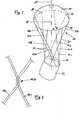
- a rotary parachute 10 is shown, consisting essentially of a cap 11, which is connected to a load carrier 13 via lines 12.
- the load carrier 13 is the load itself in the illustrated embodiment.
- the cap 11 of the parachute is made in the usual way from different webs and has different openings (not shown) through which air can flow.
- a total of 8 lines 12 are attached to each other at equal intervals.
- the attachment is carried out in the usual way, for example by sewing, clamping, riveting, knots, etc.
- suspension lines 12 now run from the lower edge 14 of the cap 11 to the upper edge of the load 13, on which they are also attached in a stationary manner.
- the connection of the suspension lines 12 to the load 13 takes place in a similar manner to the cap 11.
- each line 12 is offset from the (imaginary) central longitudinal axis 15 of the parachute 10, that is, the individual lines 12 are arranged so that they do not have an overall common point of intersection have imaginary extensions towards the load 13.
- the individual suspension line 12 is arranged such that when a longitudinal section is made through the parachute, both the corresponding suspension line attachment point 16 on the cap 11 and the central longitudinal axis 15 of the parachute 10 in the cutting surface lie at a certain angle this imaginary intersection runs.
- 4 suspension lines 12a to d are arranged such that they extend obliquely in the direction of rotation R between cap 11 and load 13, while the remaining 4 suspension lines 12e to h are attached with opposite inclinations between cap 11 and load 13.
- each suspension line 12 crosses at least two other suspension lines.
- the safety line 12b passes the safety lines 12e and 12h in the nodes 19, 20.
- each of the intersecting safety lines are connected to one another in a shear-resistant manner.
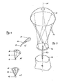
- FIG 2 an embodiment of such a shear-resistant connection is shown.
- the safety lines 12 designed as braided lines are spliced three times to one another, as a result of which an extremely secure connection of the safety lines 12 to one another is achieved.
- S o is formed a "solid" triangle, for example, through the node 19, which is formed by the corner points of intersection 19 and the suspension line attachment points of the suspension lines 12b and 12e to the load. 13
- the nodes 19, 20, which, as can be seen in FIG. 1, also exist between all the other lines 12, are of particular importance insofar as they can avoid displacements of the individual paths of the cap 11.
- the flexibility of the cap 11 would cause relative shifts, if the safety lines were not connected to one another in a fixed manner by corresponding nodes, which would adversely affect the fall behavior of such a parachute.
- the load 13 is suspended obliquely, that is, the surface of the load 13 is not parallel to the surface formed by the lower edge 14 of the cap 11, or in other words, the surface of the load 13 is vertical Case of the parachute 10 is not arranged horizontally. This is achieved in that the individual suspension lines 12 have a different length. As can be seen in FIG. 1 without any problems, the safety line 12e, for example, is significantly longer than the safety line 12h.
- a parachute with the features according to the invention has an exceptionally good fall behavior, a particularly favorable inherent stability and a minimal pendulum angle.
- the fall behavior can be further improved if a pull line (not shown) is incorporated in the area of the lower edge (base) 14 of the parachute cap 11 is.
- This pull line should then run from one suspension line attachment point to the other and be attached to the suspension line attachment points in each case.
- the length between each two adjacent suspension line connection points must be less than the length of the lower edge 14 of the cap 11 formed between the two suspension line connection points. This ensures that the distance between the suspension line connection points remains the same even with an air-filled cap, so that the fall behavior of the Parachute is not affected. In the air-filled state, this results in the shape of a polygon for the towing line (under supervision), the number of corners corresponding to the number of tether lines.
- the pull cord provided is arranged on the inside of the cap on its lower peripheral edge 14 in a manner similar to a reefing line. When the cap is full, the line is straight.
- FIG. 3 shows an exemplary embodiment of a recovery system according to the invention, in which an intermediate member 22 is arranged between the rotating parachute 10 and the load 13.
- a flexible shaft 23 runs vertically downward from the intermediate member 22 and is attached to the load 13 at the other end.
- the shaft 23 is detachably arranged between the intermediate member 22 and the load 13 so that it can be easily removed after the parachute has collapsed.
- the load 13 can be suspended eccentrically on the shaft 23.
- the shaft 23 or another connection at this point between the cap 11 and the load 13 must be such that it is on the one hand non-rotatable but on the other hand creates a flexible connection to the load 13. In particular, it must not turn itself up.
- FIG. 4 shows how a parachute according to the invention unfolds and then descends.
- the load 13 is suspended at an angle.
- stage b After the parachute has been released (stage a), the parachute deploys to such an extent that it reaches its full filling (stage b).
- the rotation of the parachute canopy is, for example, 2 revolutions / sec. A short time later the stationary state is reached, with the canopy 11 and load 13 rotating synchronously twice a second.
- a rotary parachute according to the invention or a complete rescue system are suitable for a variety of uses.
- the use for location purposes or the use of cameras for all-round photography may be mentioned here.
- the transmitted torque is greater, the further away the suspension line connection points on the load 13 are from the (imaginary) central longitudinal axis of the parachute.
Landscapes
- Engineering & Computer Science (AREA)
- Aviation & Aerospace Engineering (AREA)
- Toys (AREA)
Applications Claiming Priority (2)
| Application Number | Priority Date | Filing Date | Title |
|---|---|---|---|
| DE19833341990 DE3341990A1 (de) | 1983-11-22 | 1983-11-22 | Rotationsfallschirm |
| DE3341990 | 1983-11-22 |
Publications (1)
| Publication Number | Publication Date |
|---|---|
| EP0144035A1 true EP0144035A1 (de) | 1985-06-12 |
Family
ID=6214830
Family Applications (1)
| Application Number | Title | Priority Date | Filing Date |
|---|---|---|---|
| EP84113945A Ceased EP0144035A1 (de) | 1983-11-22 | 1984-11-17 | Rotationsfallschirm |
Country Status (3)
| Country | Link |
|---|---|
| US (1) | US4635884A (Sortimente) |
| EP (1) | EP0144035A1 (Sortimente) |
| DE (1) | DE3341990A1 (Sortimente) |
Families Citing this family (6)
| Publication number | Priority date | Publication date | Assignee | Title |
|---|---|---|---|---|
| GB8603473D0 (en) * | 1986-02-12 | 1986-03-19 | Marconi Co Ltd | Mooring tether |
| US4844384A (en) * | 1987-05-15 | 1989-07-04 | Barish David T | Rotating parachute |
| DE3827123C2 (de) * | 1988-08-10 | 1999-07-01 | Giws Ges Fuer Intelligente Wir | Flugkörper zum Absetzen einer Last |
| DE3913171A1 (de) * | 1988-12-23 | 1990-10-25 | Diehl Gmbh & Co | Aus einem fluggeraet ausstossbare submunition |
| US10836483B2 (en) * | 2009-09-11 | 2020-11-17 | Aerovironment, Inc. | Ad hoc dynamic data link repeater |
| WO2017015310A2 (en) | 2015-07-20 | 2017-01-26 | Aerovironment, Inc. | Ad hoc dynamic data link repeater |
Citations (3)
| Publication number | Priority date | Publication date | Assignee | Title |
|---|---|---|---|---|
| US2797885A (en) * | 1954-02-11 | 1957-07-02 | Barish David Theodore | Vortex ring parachute |
| US3433441A (en) * | 1966-05-16 | 1969-03-18 | North American Rockwell | Flexible aerodynamic body |
| GB1443196A (en) * | 1973-09-25 | 1976-07-21 | Rfd Co Ltd | Parachutes |
Family Cites Families (7)
| Publication number | Priority date | Publication date | Assignee | Title |
|---|---|---|---|---|
| GB192136A (en) * | 1921-10-21 | 1923-01-22 | V M L Ex Ltd | Improvements in or relating to parachutes |
| US1855320A (en) * | 1929-07-01 | 1932-04-26 | Neverfale Parachute Corp | Parachute |
| US2125198A (en) * | 1936-10-12 | 1938-07-26 | Irving Air Chute Gb Ltd | Parachute construction |
| US2411868A (en) * | 1943-06-24 | 1946-12-03 | Graham B Brown | Parachute |
| US2701697A (en) * | 1949-11-14 | 1955-02-08 | Radioplane Company | Rotating parachute |
| FR1174640A (fr) * | 1957-05-07 | 1959-03-13 | Luceber Ets | Perfectionnement aux parachutes |
| US3493199A (en) * | 1967-09-19 | 1970-02-03 | Abraham Flatau | Autorotating parachute |
-
1983
- 1983-11-22 DE DE19833341990 patent/DE3341990A1/de active Granted
-
1984
- 1984-11-17 EP EP84113945A patent/EP0144035A1/de not_active Ceased
- 1984-11-19 US US06/673,045 patent/US4635884A/en not_active Expired - Fee Related
Patent Citations (3)
| Publication number | Priority date | Publication date | Assignee | Title |
|---|---|---|---|---|
| US2797885A (en) * | 1954-02-11 | 1957-07-02 | Barish David Theodore | Vortex ring parachute |
| US3433441A (en) * | 1966-05-16 | 1969-03-18 | North American Rockwell | Flexible aerodynamic body |
| GB1443196A (en) * | 1973-09-25 | 1976-07-21 | Rfd Co Ltd | Parachutes |
Also Published As
| Publication number | Publication date |
|---|---|
| US4635884A (en) | 1987-01-13 |
| DE3341990A1 (de) | 1985-05-30 |
| DE3341990C2 (Sortimente) | 1992-10-29 |
Similar Documents
| Publication | Publication Date | Title |
|---|---|---|
| DE1931732A1 (de) | Fernbedienungseinrichtung | |
| EP1345731A1 (de) | Gliederschürze zur abdeckung von maschinenteilen | |
| DE1406575C3 (de) | Fallschirm | |
| DE3341990C2 (Sortimente) | ||
| EP0726192A1 (de) | Sicherheitssystem für Lenkwellen | |
| DE102004055111A1 (de) | Rahmen-Glas-Verbund | |
| DE19952976B4 (de) | Angetriebenes Scharnier mit automatischer, antriebsbetätigter Sperrvorrichtung | |
| DE4113725A1 (de) | Anordnung fuer eine loesbare verbindung von flexiblen bahnen oder dergleichen an mit nuten versehenen profilen | |
| DE4027906C2 (de) | Schultergurteinstelleinrichtung für einen Sitzgurt | |
| DE2544989C3 (de) | Vorrichtung zum Abtrennen der Aufziehvorrichtung eines Fallschirmes | |
| DE2630520C2 (de) | Fernverstellbarer Fahrzeugaußenspiegel | |
| EP1667879A1 (de) | Selbstsperrender gurtaufroller | |
| DE3236533A1 (de) | Fallschirm | |
| DE2655373A1 (de) | Vorrichtung zum verhindern des schwingens eines an einem seil o.dgl. haengenden koerpers | |
| DE69300265T2 (de) | Einrichtung an Planen. | |
| DE8333390U1 (de) | Rotationsfallschirm | |
| EP4214379A1 (de) | Anschlusseinrichtung für ein gerüstsystem zur montage eines gerüstgeländerstabs | |
| DE9209155U1 (de) | Stellorgan | |
| DE102010005910B4 (de) | Verdrillschutzanordnung | |
| DE3208576A1 (de) | Rohrverbindung | |
| CH715712A1 (de) | Verschlusskappe zum Verschliessen eines Behälters und Behälter mit einer solchen unverlierbar gehaltenen Verschlusskappe. | |
| DE3201058A1 (de) | "schutzabdeckung fuer wellen, spindeln, flachbahnen od. dgl.zumindest teilweise freiliegende maschinenelemente" | |
| DE10210885C1 (de) | Regalsystem mit Profilrohren und Knotenelementen | |
| DE2507522C2 (de) | Sicherungsring | |
| DE3446275C1 (de) | Umlaufender Bohrkopf mit einer zwischen einem Anschlussschaft und einem Werkzeugtraeger angeordneten Zustelleinrichtung |
Legal Events
| Date | Code | Title | Description |
|---|---|---|---|
| PUAI | Public reference made under article 153(3) epc to a published international application that has entered the european phase |
Free format text: ORIGINAL CODE: 0009012 |
|
| AK | Designated contracting states |
Designated state(s): FR GB IT |
|
| 17P | Request for examination filed |
Effective date: 19851203 |
|
| 17Q | First examination report despatched |
Effective date: 19861125 |
|
| STAA | Information on the status of an ep patent application or granted ep patent |
Free format text: STATUS: THE APPLICATION HAS BEEN REFUSED |
|
| 18R | Application refused |
Effective date: 19871206 |
|
| RIN1 | Information on inventor provided before grant (corrected) |
Inventor name: NOEHREN, HUBERT |