EP0143900B1 - Hilfseinrichtung zum Regulieren der Helligkeit von Niederspannungs-Leuchtstofflampen - Google Patents
Hilfseinrichtung zum Regulieren der Helligkeit von Niederspannungs-Leuchtstofflampen Download PDFInfo
- Publication number
- EP0143900B1 EP0143900B1 EP84110014A EP84110014A EP0143900B1 EP 0143900 B1 EP0143900 B1 EP 0143900B1 EP 84110014 A EP84110014 A EP 84110014A EP 84110014 A EP84110014 A EP 84110014A EP 0143900 B1 EP0143900 B1 EP 0143900B1
- Authority
- EP
- European Patent Office
- Prior art keywords
- side terminal
- terminal connection
- lamp
- line
- connection
- Prior art date
- Legal status (The legal status is an assumption and is not a legal conclusion. Google has not performed a legal analysis and makes no representation as to the accuracy of the status listed.)
- Expired
Links
- 230000001105 regulatory effect Effects 0.000 title claims abstract description 8
- 239000004020 conductor Substances 0.000 claims abstract description 21
- 230000001939 inductive effect Effects 0.000 claims abstract description 7
- XEEYBQQBJWHFJM-UHFFFAOYSA-N Iron Chemical group [Fe] XEEYBQQBJWHFJM-UHFFFAOYSA-N 0.000 claims abstract description 3
- 230000001276 controlling effect Effects 0.000 claims abstract 2
- 238000004804 winding Methods 0.000 claims description 13
- 239000003990 capacitor Substances 0.000 claims description 4
- 238000011144 upstream manufacturing Methods 0.000 description 2
- 238000010438 heat treatment Methods 0.000 description 1
- 238000000034 method Methods 0.000 description 1
Images
Classifications
-
- H—ELECTRICITY
- H05—ELECTRIC TECHNIQUES NOT OTHERWISE PROVIDED FOR
- H05B—ELECTRIC HEATING; ELECTRIC LIGHT SOURCES NOT OTHERWISE PROVIDED FOR; CIRCUIT ARRANGEMENTS FOR ELECTRIC LIGHT SOURCES, IN GENERAL
- H05B41/00—Circuit arrangements or apparatus for igniting or operating discharge lamps
- H05B41/14—Circuit arrangements
- H05B41/36—Controlling
- H05B41/38—Controlling the intensity of light
- H05B41/39—Controlling the intensity of light continuously
- H05B41/392—Controlling the intensity of light continuously using semiconductor devices, e.g. thyristor
- H05B41/3921—Controlling the intensity of light continuously using semiconductor devices, e.g. thyristor with possibility of light intensity variations
- H05B41/3924—Controlling the intensity of light continuously using semiconductor devices, e.g. thyristor with possibility of light intensity variations by phase control, e.g. using a triac
Definitions
- the invention relates to an auxiliary device for regulating the brightness of low-voltage fluorescent lamps with ballast by means of phase gating-controlling dimmers, in particular according to the preamble of claim 1.
- phase control dimmers often also called voltage control dimmers, which regulate the brightness of lamps by varying the voltage.
- voltage control dimmers In the case of low-voltage fluorescent lamps, there is only a regulation range of just under 10%, since low-voltage fluorescent lamps go out at a voltage below 200 volts. There are therefore special dimmers on the market that are technically and economically complex.
- auxiliary device for dimming fluorescent lamps (GB-A-2 079 551) it is ensured that the heating of the fluorescent lamp is switched on during the dimming process. In this case, extensive circuitry expenditure is required between the dimmer and the electronic valve and to the fluorescent lamp. Nevertheless, as is well known, such measures make the regulatory area relatively narrow.
- the object of the invention is to develop an improved auxiliary device for regulating the brightness of low-voltage fluorescent lamps by means of commercially available phase gating-controlling dimmers.
- the described object is achieved by an auxiliary device according to claim 1.
- the dimmer is not inductively loaded by the series reactor and the high-voltage coil ensures basic ionization in the lowest lighting stage.
- the high-voltage coil can be particularly easily integrated into the auxiliary device in a quick-start device known per se.
- the high-voltage coil can in particular be designed for a voltage on the output side of approximately 600 to 1500 volts.
- the two secondary windings of the inductively operating quick start device ensure that the lamp electrodes are heated in the usual way.
- An auxiliary device with a high-voltage coil makes it possible to regulate the brightness of low-voltage fluorescent lamps particularly far.
- the auxiliary device can also be retrofitted between the lamp-side connections and the mains-side connections for the ballast choke and for the dimmer and for the center conductor connection.
- the electronic valve can be a triac with a capacitor connected upstream on the control side.
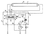
- the low-voltage fluorescent lamp 1 is limited in the usual way in its current consumption by the ballast 2.
- the brightness of the lamp can be regulated by means of a commercially available phase control dimmer 3.
- an auxiliary device 4 is interposed. It consists essentially of an electronic valve 5 with a line-side connection 6 for the series choke and a line-side connection 8 for the dimmer 3 leading to the control electrode 7 of the electronic valve 5.
- Further line-side connections 9 and 66, which are independent of the electronic valve, are for the center conductor M and provided for connecting the outer conductor L1. The potential of the center conductor is led to the connection 10 on the lamp side.
- the output of the electronic valve 5 is connected to a lamp-side connection 14.
- the electronic valve 5 is shown as a triac with a capacitor 11 connected upstream on the control side.
- this capacitor 11 can have a capacitance of approximately 01.1 J, 1.F. It differentiates the control voltage so that a voltage jump from the phase gating dimmer leads to the ignition of the triac 5.
- auxiliary device 4 also includes the devices for an inductive quick start device 12 of a known type, a high-voltage coil 13 can be easily integrated with it. Between the mains-side connection 9 for the center conductor M and the lamp-side connection 14 of the electronic control valve 5, the high-voltage coil 13 is advantageously switched on, which is coupled to the iron core 15 of the inductive quick start device 12.
- the high-voltage coil 13 can advantageously be designed so that it outputs a voltage in the range of 600 to 1500 volts at its terminals.
- the inductive quick start device 12 is advantageously in one shared housing.
- the quick-start device 12 with its primary winding 16 is switched on between the network-side connection 9 for the center conductor M and the network-side connection 66 for the outer conductor L1.
- a connection to a further connection 19 and a further connection to the lamp-side connection 14 of the electronic control valve 5 is formed from the other secondary winding 18.
- a current limiting resistor 20 of approximately 3.3 megohms can be switched on.
- the grounded lamp housing, which is symbolized by 21, can serve as a further starting aid for the low-voltage fluorescent lamp 1.
- the load circuit of the low-voltage fluorescent lamp is formed on the mains side by an outer conductor L1 connected to the ballast choke 2 and by the center conductor connected to the connection 9, the potential of the outer conductor, designated L2, also being supplied to the dimmer 3, as a result of which the low-voltage fluorescent lamp is at its brightness can be regulated.
Landscapes
- Engineering & Computer Science (AREA)
- Power Engineering (AREA)
- Discharge-Lamp Control Circuits And Pulse- Feed Circuits (AREA)
- Lighting Device Outwards From Vehicle And Optical Signal (AREA)
- Circuit Arrangements For Discharge Lamps (AREA)
Priority Applications (1)
| Application Number | Priority Date | Filing Date | Title |
|---|---|---|---|
| AT84110014T ATE41583T1 (de) | 1983-09-05 | 1984-08-22 | Hilfseinrichtung zum regulieren der helligkeit von niederspannungs-leuchtstofflampen. |
Applications Claiming Priority (2)
| Application Number | Priority Date | Filing Date | Title |
|---|---|---|---|
| DE3331996 | 1983-09-05 | ||
| DE19833331996 DE3331996A1 (de) | 1983-09-05 | 1983-09-05 | Hilfseinrichtung zum regulieren der helligkeit von niederspannungs-leuchtstofflampen |
Publications (2)
| Publication Number | Publication Date |
|---|---|
| EP0143900A1 EP0143900A1 (de) | 1985-06-12 |
| EP0143900B1 true EP0143900B1 (de) | 1989-03-15 |
Family
ID=6208283
Family Applications (1)
| Application Number | Title | Priority Date | Filing Date |
|---|---|---|---|
| EP84110014A Expired EP0143900B1 (de) | 1983-09-05 | 1984-08-22 | Hilfseinrichtung zum Regulieren der Helligkeit von Niederspannungs-Leuchtstofflampen |
Country Status (5)
| Country | Link |
|---|---|
| EP (1) | EP0143900B1 (da) |
| AT (1) | ATE41583T1 (da) |
| DE (2) | DE3331996A1 (da) |
| DK (1) | DK96884A (da) |
| NO (1) | NO842314L (da) |
Families Citing this family (2)
| Publication number | Priority date | Publication date | Assignee | Title |
|---|---|---|---|---|
| HU202701B (en) * | 1989-05-25 | 1991-03-28 | Jozsef Ladanyi | Fluorescent lamp unit of controllable light intensity |
| DE4218959A1 (de) * | 1991-07-11 | 1993-01-14 | Bosch Gmbh Robert | Schaltungsanordnung zum betrieb einer leuchtstofflampe |
Family Cites Families (5)
| Publication number | Priority date | Publication date | Assignee | Title |
|---|---|---|---|---|
| US3935505A (en) * | 1974-01-21 | 1976-01-27 | Joseph Spiteri | Fluorescent lamp dimmer |
| DE2508923A1 (de) * | 1975-03-01 | 1976-09-09 | Bbc Brown Boveri & Cie | Elektronische zusatzschaltungsanordnung |
| CA1106908A (en) * | 1977-04-21 | 1981-08-11 | Zoltan L. Gyursanzsky | Two-wire ballast for fluorescent tube dimming |
| CH630766A5 (de) * | 1978-07-31 | 1982-06-30 | Evers Poul Hahn | Einrichtung zur regulierung der helligkeit mindestens einer leuchtstofflampe. |
| GB2079551A (en) * | 1980-07-04 | 1982-01-20 | Home Automation Ltd | Improvements in dimming of fluorescent lights |
-
1983
- 1983-09-05 DE DE19833331996 patent/DE3331996A1/de not_active Withdrawn
-
1984
- 1984-02-24 DK DK96884A patent/DK96884A/da not_active Application Discontinuation
- 1984-06-08 NO NO842314A patent/NO842314L/no unknown
- 1984-08-22 EP EP84110014A patent/EP0143900B1/de not_active Expired
- 1984-08-22 AT AT84110014T patent/ATE41583T1/de not_active IP Right Cessation
- 1984-08-22 DE DE8484110014T patent/DE3477339D1/de not_active Expired
Also Published As
| Publication number | Publication date |
|---|---|
| DK96884D0 (da) | 1984-02-24 |
| EP0143900A1 (de) | 1985-06-12 |
| DK96884A (da) | 1985-03-06 |
| DE3331996A1 (de) | 1985-03-21 |
| DE3477339D1 (en) | 1989-04-20 |
| ATE41583T1 (de) | 1989-04-15 |
| NO842314L (no) | 1985-03-06 |
Similar Documents
| Publication | Publication Date | Title |
|---|---|---|
| DE2263582C2 (de) | Anordnung zum Zünden und Betrieb einer Niederdruckquecksilberdampfentladungslampe | |
| DE3879548T2 (de) | Wechselrichter zum Zünden und Speisen einer Gasentladungslampe. | |
| DE2903224C2 (de) | Schaltungsanordnung zum Zünden und Speisen einer mit einer vorheizbaren Elektrode versehenen Metalldampfentladungslampe | |
| DE2816715C2 (de) | Speiseschaltung für Leuchtstoffröhren | |
| DE29705183U1 (de) | Betriebsschaltung für Hochdruckgasentladungslampen mit Zündzeitüberbrückungsfunktion | |
| EP0488002B1 (de) | Verfahren und Einrichtung zur Steuerung von Gasentladungslampen mit elektronischen Vorschaltgeräten | |
| EP1467474A2 (de) | Schnittstellenschaltung zum Betrieb von kapazitiven Lasten | |
| DE3235197A1 (de) | Vorrichtung zur begrenzung und regelung des stroms einer gasentladungslampe | |
| EP0208083B1 (de) | Dimmerschaltung für ein elektronisches Leuchtstofflampen-Vorschaltgerät | |
| EP0143900B1 (de) | Hilfseinrichtung zum Regulieren der Helligkeit von Niederspannungs-Leuchtstofflampen | |
| DE102005030115A1 (de) | Schaltungsanordnung und Verfahren zum Betrieb mindestens einer LED und mindestens einer elektrischen Lampe | |
| DE102005030114A1 (de) | Schaltungsanordnung und Verfahren zum Betrieb mindestens einer elektrischen Lampe und mindestens einer LED | |
| DE4219958C1 (en) | Ballast circuit for discharge lamp - uses phase gate control to short out electrodes for interval in each half cycle, depending on brightness | |
| DE1224837B (de) | In mehreren Helligkeitsstufen zu betreibende Leuchte mit mehreren Leuchtstofflampen | |
| DE3345559C2 (da) | ||
| DE19541341C2 (de) | Transformator | |
| EP0111296B1 (de) | Anordnung zur Steuerung der Helligkeit einer Niederdruckentladungslampe | |
| DE4220291C1 (en) | Ballast circuit for fluorescent lamp with dimmer - includes source supplying brightness signal for control stage for transistor switch bridging lamp electrodes | |
| EP0104397B1 (de) | Schaltungsanordnung zur Verminderung der Leistungsaufnahme einer Leuchtstofflampe | |
| EP0201973A1 (de) | Schaltungsanordnung zum Betrieb von Gasentladungslampen mit periodisch wechselndem Lampenstrom | |
| DE29514817U1 (de) | Schaltungsanordnung zum Betrieb mindestens einer Niederdruckentladungslampe | |
| DE2029050A1 (de) | Anordnung zum Abblenden mindestens zweier parallel geschalteter Entladungs lampen | |
| EP0599887B1 (de) | Vorrichtung zum betreiben einer gasentladungslampe | |
| DE2439606A1 (de) | Universal-leuchtstofflampenhandleuchte mit transistorisiertem vorschaltgeraet | |
| DE19903015A1 (de) | Dimmbares Vorschaltgerät für Kaltkathoden-Fluoreszenzlampen |
Legal Events
| Date | Code | Title | Description |
|---|---|---|---|
| PUAI | Public reference made under article 153(3) epc to a published international application that has entered the european phase |
Free format text: ORIGINAL CODE: 0009012 |
|
| AK | Designated contracting states |
Designated state(s): AT CH DE FR IT LI SE |
|
| 17P | Request for examination filed |
Effective date: 19851126 |
|
| 17Q | First examination report despatched |
Effective date: 19870720 |
|
| GRAA | (expected) grant |
Free format text: ORIGINAL CODE: 0009210 |
|
| AK | Designated contracting states |
Kind code of ref document: B1 Designated state(s): AT CH DE FR IT LI SE |
|
| PG25 | Lapsed in a contracting state [announced via postgrant information from national office to epo] |
Ref country code: SE Effective date: 19890315 Ref country code: IT Free format text: LAPSE BECAUSE OF FAILURE TO SUBMIT A TRANSLATION OF THE DESCRIPTION OR TO PAY THE FEE WITHIN THE PRESCRIBED TIME-LIMIT;WARNING: LAPSES OF ITALIAN PATENTS WITH EFFECTIVE DATE BEFORE 2007 MAY HAVE OCCURRED AT ANY TIME BEFORE 2007. THE CORRECT EFFECTIVE DATE MAY BE DIFFERENT FROM THE ONE RECORDED. Effective date: 19890315 Ref country code: FR Free format text: THE PATENT HAS BEEN ANNULLED BY A DECISION OF A NATIONAL AUTHORITY Effective date: 19890315 |
|
| REF | Corresponds to: |
Ref document number: 41583 Country of ref document: AT Date of ref document: 19890415 Kind code of ref document: T |
|
| REF | Corresponds to: |
Ref document number: 3477339 Country of ref document: DE Date of ref document: 19890420 |
|
| EN | Fr: translation not filed | ||
| PLBE | No opposition filed within time limit |
Free format text: ORIGINAL CODE: 0009261 |
|
| STAA | Information on the status of an ep patent application or granted ep patent |
Free format text: STATUS: NO OPPOSITION FILED WITHIN TIME LIMIT |
|
| PGFP | Annual fee paid to national office [announced via postgrant information from national office to epo] |
Ref country code: CH Payment date: 19900227 Year of fee payment: 6 |
|
| 26N | No opposition filed | ||
| PGFP | Annual fee paid to national office [announced via postgrant information from national office to epo] |
Ref country code: DE Payment date: 19900410 Year of fee payment: 6 |
|
| REG | Reference to a national code |
Ref country code: CH Ref legal event code: PUE Owner name: ECKHARD FROEBEL |
|
| PG25 | Lapsed in a contracting state [announced via postgrant information from national office to epo] |
Ref country code: LI Effective date: 19900831 Ref country code: CH Effective date: 19900831 |
|
| REG | Reference to a national code |
Ref country code: CH Ref legal event code: PL |
|
| PG25 | Lapsed in a contracting state [announced via postgrant information from national office to epo] |
Ref country code: DE Effective date: 19910501 |
|
| PGFP | Annual fee paid to national office [announced via postgrant information from national office to epo] |
Ref country code: AT Payment date: 19920917 Year of fee payment: 9 |
|
| PG25 | Lapsed in a contracting state [announced via postgrant information from national office to epo] |
Ref country code: AT Effective date: 19930822 |