EP0143900B1 - Auxiliary device for regulating the intensity of low voltage fluorescent lamps - Google Patents
Auxiliary device for regulating the intensity of low voltage fluorescent lamps Download PDFInfo
- Publication number
- EP0143900B1 EP0143900B1 EP84110014A EP84110014A EP0143900B1 EP 0143900 B1 EP0143900 B1 EP 0143900B1 EP 84110014 A EP84110014 A EP 84110014A EP 84110014 A EP84110014 A EP 84110014A EP 0143900 B1 EP0143900 B1 EP 0143900B1
- Authority
- EP
- European Patent Office
- Prior art keywords
- side terminal
- terminal connection
- lamp
- line
- connection
- Prior art date
- Legal status (The legal status is an assumption and is not a legal conclusion. Google has not performed a legal analysis and makes no representation as to the accuracy of the status listed.)
- Expired
Links
Images
Classifications
-
- H—ELECTRICITY
- H05—ELECTRIC TECHNIQUES NOT OTHERWISE PROVIDED FOR
- H05B—ELECTRIC HEATING; ELECTRIC LIGHT SOURCES NOT OTHERWISE PROVIDED FOR; CIRCUIT ARRANGEMENTS FOR ELECTRIC LIGHT SOURCES, IN GENERAL
- H05B41/00—Circuit arrangements or apparatus for igniting or operating discharge lamps
- H05B41/14—Circuit arrangements
- H05B41/36—Controlling
- H05B41/38—Controlling the intensity of light
- H05B41/39—Controlling the intensity of light continuously
- H05B41/392—Controlling the intensity of light continuously using semiconductor devices, e.g. thyristor
- H05B41/3921—Controlling the intensity of light continuously using semiconductor devices, e.g. thyristor with possibility of light intensity variations
- H05B41/3924—Controlling the intensity of light continuously using semiconductor devices, e.g. thyristor with possibility of light intensity variations by phase control, e.g. using a triac
Definitions
- the invention relates to an auxiliary device for regulating the brightness of low-voltage fluorescent lamps with ballast by means of phase gating-controlling dimmers, in particular according to the preamble of claim 1.
- phase control dimmers often also called voltage control dimmers, which regulate the brightness of lamps by varying the voltage.
- voltage control dimmers In the case of low-voltage fluorescent lamps, there is only a regulation range of just under 10%, since low-voltage fluorescent lamps go out at a voltage below 200 volts. There are therefore special dimmers on the market that are technically and economically complex.
- auxiliary device for dimming fluorescent lamps (GB-A-2 079 551) it is ensured that the heating of the fluorescent lamp is switched on during the dimming process. In this case, extensive circuitry expenditure is required between the dimmer and the electronic valve and to the fluorescent lamp. Nevertheless, as is well known, such measures make the regulatory area relatively narrow.
- the object of the invention is to develop an improved auxiliary device for regulating the brightness of low-voltage fluorescent lamps by means of commercially available phase gating-controlling dimmers.
- the described object is achieved by an auxiliary device according to claim 1.
- the dimmer is not inductively loaded by the series reactor and the high-voltage coil ensures basic ionization in the lowest lighting stage.
- the high-voltage coil can be particularly easily integrated into the auxiliary device in a quick-start device known per se.
- the high-voltage coil can in particular be designed for a voltage on the output side of approximately 600 to 1500 volts.
- the two secondary windings of the inductively operating quick start device ensure that the lamp electrodes are heated in the usual way.
- An auxiliary device with a high-voltage coil makes it possible to regulate the brightness of low-voltage fluorescent lamps particularly far.
- the auxiliary device can also be retrofitted between the lamp-side connections and the mains-side connections for the ballast choke and for the dimmer and for the center conductor connection.
- the electronic valve can be a triac with a capacitor connected upstream on the control side.
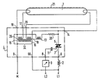
- the low-voltage fluorescent lamp 1 is limited in the usual way in its current consumption by the ballast 2.
- the brightness of the lamp can be regulated by means of a commercially available phase control dimmer 3.
- an auxiliary device 4 is interposed. It consists essentially of an electronic valve 5 with a line-side connection 6 for the series choke and a line-side connection 8 for the dimmer 3 leading to the control electrode 7 of the electronic valve 5.
- Further line-side connections 9 and 66, which are independent of the electronic valve, are for the center conductor M and provided for connecting the outer conductor L1. The potential of the center conductor is led to the connection 10 on the lamp side.
- the output of the electronic valve 5 is connected to a lamp-side connection 14.
- the electronic valve 5 is shown as a triac with a capacitor 11 connected upstream on the control side.
- this capacitor 11 can have a capacitance of approximately 01.1 J, 1.F. It differentiates the control voltage so that a voltage jump from the phase gating dimmer leads to the ignition of the triac 5.
- auxiliary device 4 also includes the devices for an inductive quick start device 12 of a known type, a high-voltage coil 13 can be easily integrated with it. Between the mains-side connection 9 for the center conductor M and the lamp-side connection 14 of the electronic control valve 5, the high-voltage coil 13 is advantageously switched on, which is coupled to the iron core 15 of the inductive quick start device 12.
- the high-voltage coil 13 can advantageously be designed so that it outputs a voltage in the range of 600 to 1500 volts at its terminals.
- the inductive quick start device 12 is advantageously in one shared housing.
- the quick-start device 12 with its primary winding 16 is switched on between the network-side connection 9 for the center conductor M and the network-side connection 66 for the outer conductor L1.
- a connection to a further connection 19 and a further connection to the lamp-side connection 14 of the electronic control valve 5 is formed from the other secondary winding 18.
- a current limiting resistor 20 of approximately 3.3 megohms can be switched on.
- the grounded lamp housing, which is symbolized by 21, can serve as a further starting aid for the low-voltage fluorescent lamp 1.
- the load circuit of the low-voltage fluorescent lamp is formed on the mains side by an outer conductor L1 connected to the ballast choke 2 and by the center conductor connected to the connection 9, the potential of the outer conductor, designated L2, also being supplied to the dimmer 3, as a result of which the low-voltage fluorescent lamp is at its brightness can be regulated.
Abstract
Description
Die Erfindung bezieht sich auf eine Hilfseinrichtung zum Regulieren der Helligkeit von Niederspannungs-Leuchtstofflampen mit Vorschaltdrossel durch phasenanschnittkontrollierende Dimmer, im einzelnen nach Gattungsbegriff von Patentanspruch 1.The invention relates to an auxiliary device for regulating the brightness of low-voltage fluorescent lamps with ballast by means of phase gating-controlling dimmers, in particular according to the preamble of claim 1.
Die einfachsten und auf dem Markt am häufigsten vorhandenen Dimmer sind phasenanschnittkontrollierende Dimmer, oft auch spannungskontrollierende Dimmer genannt, die also durch eine variierende Spannung die Helligkeit von Lampen regulieren. Bei Niederspannungs-Leuchtstofflampen bleibt hierfür lediglich ein Regulierungsbereich von knapp 10 %, da Niederspannungs-Leuchtstofflampen bei einer Spannung unterhalb 200 Volt erlöschen. Es sind daher Spezialdimmer auf dem Markt, die technisch und wirtschaftlich aufwendig sind.The simplest and most frequently available dimmers on the market are phase control dimmers, often also called voltage control dimmers, which regulate the brightness of lamps by varying the voltage. In the case of low-voltage fluorescent lamps, there is only a regulation range of just under 10%, since low-voltage fluorescent lamps go out at a voltage below 200 volts. There are therefore special dimmers on the market that are technically and economically complex.
Nach einer bekannten Hilfseinrichtung zum Dimmen von Leuchtstofflampen (GB-A-2 079 551) wird dafür gesorgt, daß während des Dimmvorgangs die Heizung der Leuchtstofflampe eingeschaltet ist. Hierbei sind zwischen Dimmer und elektronischem Ventil und zur Leuchtstofflampe umfangreiche schaltungstechnische Aufwendungen erforderlich. Dennoch ist bekanntlich durch derartige Maßnahmen der Regulierungsbereich verhältnismäßig eng.According to a known auxiliary device for dimming fluorescent lamps (GB-A-2 079 551) it is ensured that the heating of the fluorescent lamp is switched on during the dimming process. In this case, extensive circuitry expenditure is required between the dimmer and the electronic valve and to the fluorescent lamp. Nevertheless, as is well known, such measures make the regulatory area relatively narrow.
Der Erfindung liegt die Aufgabe zugrunde, eine verbesserte Hilfseinrichtung zum Regulieren der Helligkeit von Niederspannungs-Leuchtstofflampen durch marktübliche phasenanschnittkontrollierende Dimmer zu entwickeln.The object of the invention is to develop an improved auxiliary device for regulating the brightness of low-voltage fluorescent lamps by means of commercially available phase gating-controlling dimmers.
Die Lösung der geschilderten Aufgabe erfolgt nach der Erfindung durch eine Hilfseinrichtung nach Patentanspruch 1. Durch eine solche Einrichtung wird der Dimmer durch die Vorschaltdrossel nicht induktiv belastet und die Hochspannungsspule sorgt für eine Grundionisation im untersten Leuchtstadium.According to the invention, the described object is achieved by an auxiliary device according to claim 1. By such a device, the dimmer is not inductively loaded by the series reactor and the high-voltage coil ensures basic ionization in the lowest lighting stage.
Die Hochspannungspule läßt sich bei einer schnellstarteinrichtung an sich bekannter Art besonders leicht in die Hilfseinrichtung integrieren. Die Hochspannungsspule kann insbesondere für eine abgangsseitige Spannung von etwa 600 bis 1500 Volt ausgelegt sein. Darüber hinaus sorgen bei Einsatz einer Schnellstarteinrichtung die beiden Sekundärwicklungen der induktiv arbeitenden Schnellstarteinrichtung dafür, die Lampenelektroden in üblicher Weise aufzuheizen. Eine Hilfseinrichtung mit Hochspannungsspule ermöglicht es, die Helligkeit von Niederspannungs-Leuchtstofflampen besonders weit herunterzuregeln.The high-voltage coil can be particularly easily integrated into the auxiliary device in a quick-start device known per se. The high-voltage coil can in particular be designed for a voltage on the output side of approximately 600 to 1500 volts. In addition, when using a quick start device, the two secondary windings of the inductively operating quick start device ensure that the lamp electrodes are heated in the usual way. An auxiliary device with a high-voltage coil makes it possible to regulate the brightness of low-voltage fluorescent lamps particularly far.
Die Hilfseinrichtung kann auch nachträglich zwischen den lampenseitigen Anschlüssen und den netzseitigen Anschlüssen für die Vorschaltdrossel und für den Dimmer sowie für den Mittelleiteranschluß zwischengeschaltet werden.The auxiliary device can also be retrofitted between the lamp-side connections and the mains-side connections for the ballast choke and for the dimmer and for the center conductor connection.
Das elektronische Ventil kann ein Triac mit steuerseitig vorgeschaltetem Kondensator sein.The electronic valve can be a triac with a capacitor connected upstream on the control side.
Bei Verwendung einer induktiven Schnellstarteinrichtung in einem gemeinsamen Gehäuse kann man zwischen dem netzseitigen Anschluß für den Mittelpunktleiter und dem netzseitigen Anschluß für den Außenleiter die Primärwicklung einschalten und von einer Sekundärwicklung, deren einer Pol mit dem Mittelpunktanschluß der Primärwicklung verbunden ist, Verbindungen zu lampenseitigen externen Anschlüssen führen. Von der anderen Sekundärwicklung kann man eine Verbindung zu einem weiteren lampenseitigen Anschluß und eine weitere Verbindung zum lampenseitigen Anschluß des elektronischen Steuerventils ausführen. Hierdurch erzielt man eine kompakt aufgebaute Hilfseinrichtung mit wenigen übersichtlichen externen Anschlüssen.When using an inductive quick start device in a common housing, you can switch on the primary winding between the mains connection for the center conductor and the mains connection for the outer conductor, and connections to lamp-side external connections can be made from a secondary winding, one pole of which is connected to the center connection of the primary winding . From the other secondary winding, a connection can be made to a further lamp-side connection and a further connection to the lamp-side connection of the electronic control valve. This results in a compact auxiliary device with a few clear external connections.
Die Erfindung soll anhand eines in der Zeichnung grob schematisch wiedergegebenen Ausführungsbeispiels näher erläutert werden :The invention will be explained in more detail with reference to an exemplary embodiment shown roughly schematically in the drawing:
Die Niederspannungs-Leuchtstofflampe 1 wird in üblicher Weise in ihrer Stromaufnahme durch die Vorschaltdrossel 2 begrenzt. Durch einen marktüblichen phasenanschnittkontrollierenden Dimmer 3 kann die Helligkeit der Lampe reguliert werden. Um solche einfachen Dimmer 3 verwenden zu können, ist eine Hilfseinrichtung 4 zwischengeschaltet. Sie besteht im wesentlichen aus einem elektronischen Ventil 5 mit einem netzseitigen Anschluß 6 für die Vorschaltdrossel und einem zur Steuerelektrode 7 des elektronischen Ventils 5 geführten netzseitigen Anschluß 8 für den Dimmer 3. Weitere, vom elektronischen Ventil unabhängige netzseitige Anschlüsse 9 und 66 sind für den Mittelpunktleiter M und zum Anschließen des Außenleiters L1 vorgesehen. Das Potential des Mittelpunktleiters ist zum lampenseitigen Anschluß 10 geführt. Das elektronische Ventil 5 ist mit seinem Ausgang mit einem lampenseitigen Anschluß 14 verbunden.The low-voltage fluorescent lamp 1 is limited in the usual way in its current consumption by the ballast 2. The brightness of the lamp can be regulated by means of a commercially available phase control dimmer 3. In order to be able to use such
Im Ausführungsbeispiel ist das elektronische Ventil 5 als Triac mit einem steuerseitig vorgeschalteten Kondensator 11 wiedergegeben. Dieser Kondensator 11 kann in der Praxis eine Kapazität von etwa 01,1 J,1.F aufweisen. Er differenziert die Steuerspannung, so daß ein Spannungssprung vom phasenanschnittkontrollierenden Dimmer zur Zündung des Triacs 5 führt.In the exemplary embodiment, the
Wenn die Hilfseinrichtung 4 auch die Vorrichtungen für eine induktive Schnellstarteinrichtung 12 bekannter Art umfaßt, läßt sich hiermit leicht eine Hochspannungsspule 13 integrieren. Zwischen dem netzseitigen Anschluß 9 für den Mittelpunktleiter M und dem lampenseitigen Anschluß 14 des elektronischen Steuerventils 5 ist vorteilhafterweise die Hochspannungsspule 13 eingeschaltet, die mit dem Eisenkern 15 der induktiven Schnellstarteinrichtung 12 gekoppelt ist. Die Hochspannungsspule 13 kann günstigerweise so ausgelegt werden, daß sie an ihren Klemmen etwa eine Spannung im Bereich von 600 bis 1500 Volt abgibt.If the auxiliary device 4 also includes the devices for an inductive
Die induktive Schnellstarteinrichtung 12 ist im Ausführungsbeispiel Vorteilhafterweise in einem gemeinsamen Gehäuse untergebracht. Zwischen dem netzseitigen Anschluß 9 für den Mittelpunktleiter M und dem netzseitigen Anschluß 66 für den Außenleiter L1 ist die Schnellstarteinrichtung 12 mit ihrer Primärwicklung 16 eingeschaltet. Von einer Sekundärwicklung 17, deren einer Pol mit dem Mittelpunktanschluß der Primärwicklung verbunden ist, sind Verbindungen zu Anschlüssen bzw. Anschlußklemmen 10 und 17 geführt. Von der anderen Sekundärwicklung 18 ist eine Verbindung zu einem weiteren Anschluß 19 und eine weitere Verbindung zum lampenseitigen Anschluß 14 des elektronischen Steuerventils 5 ausgebildet.In the exemplary embodiment, the inductive
In Reihe zur Hochspannungsspule 13 kann ein Strombegrenzungswiderstand 20 von etwa 3,3 Megohm eingeschaltet sein. Als weitere Starthilfe für die NiederspannungsLeuchtstofflampe 1 kann in üblicher Weise das geerdete Lampengehäuse dienen, das mit 21 symbolisiert ist.In series with the high-
Der Lastkreis der Niederpsannungs-Leuchtstofflampe wird netzseitig durch einen an der Vorschaltdrossel 2 angeschlossenen Außenleiter L1 und durch den am Anschluß 9 angeschlossenen Mittelpunktleiter gebildet, wobei das Potential des Außenleiters, mit L2 bezeichnet, auch dem Dimmer 3 zugeführt wird, wodurch die NiederspannungsLeuchtstofflampe in ihrer Helligkeit reguliert werden kann.The load circuit of the low-voltage fluorescent lamp is formed on the mains side by an outer conductor L1 connected to the ballast choke 2 and by the center conductor connected to the connection 9, the potential of the outer conductor, designated L2, also being supplied to the
Claims (3)
Priority Applications (1)
| Application Number | Priority Date | Filing Date | Title |
|---|---|---|---|
| AT84110014T ATE41583T1 (en) | 1983-09-05 | 1984-08-22 | AUXILIARY DEVICE FOR ADJUSTING THE BRIGHTNESS OF LOW VOLTAGE FLUORESCENT LAMPS. |
Applications Claiming Priority (2)
| Application Number | Priority Date | Filing Date | Title |
|---|---|---|---|
| DE19833331996 DE3331996A1 (en) | 1983-09-05 | 1983-09-05 | AUXILIARY DEVICE FOR REGULATING THE BRIGHTNESS OF LOW-VOLTAGE FLUORESCENT LAMPS |
| DE3331996 | 1983-09-05 |
Publications (2)
| Publication Number | Publication Date |
|---|---|
| EP0143900A1 EP0143900A1 (en) | 1985-06-12 |
| EP0143900B1 true EP0143900B1 (en) | 1989-03-15 |
Family
ID=6208283
Family Applications (1)
| Application Number | Title | Priority Date | Filing Date |
|---|---|---|---|
| EP84110014A Expired EP0143900B1 (en) | 1983-09-05 | 1984-08-22 | Auxiliary device for regulating the intensity of low voltage fluorescent lamps |
Country Status (5)
| Country | Link |
|---|---|
| EP (1) | EP0143900B1 (en) |
| AT (1) | ATE41583T1 (en) |
| DE (2) | DE3331996A1 (en) |
| DK (1) | DK96884A (en) |
| NO (1) | NO842314L (en) |
Families Citing this family (2)
| Publication number | Priority date | Publication date | Assignee | Title |
|---|---|---|---|---|
| HU202701B (en) * | 1989-05-25 | 1991-03-28 | Jozsef Ladanyi | Fluorescent lamp unit of controllable light intensity |
| DE4218959A1 (en) * | 1991-07-11 | 1993-01-14 | Bosch Gmbh Robert | CIRCUIT ARRANGEMENT FOR OPERATING A FLUORESCENT LAMP |
Family Cites Families (5)
| Publication number | Priority date | Publication date | Assignee | Title |
|---|---|---|---|---|
| US3935505A (en) * | 1974-01-21 | 1976-01-27 | Joseph Spiteri | Fluorescent lamp dimmer |
| DE2508923A1 (en) * | 1975-03-01 | 1976-09-09 | Bbc Brown Boveri & Cie | Control and supply circuit for fluorescent tube - has dimmer coupled via frequency dependent pulse separator, rectifier and switch to control transformer |
| CA1106908A (en) * | 1977-04-21 | 1981-08-11 | Zoltan L. Gyursanzsky | Two-wire ballast for fluorescent tube dimming |
| CH630766A5 (en) * | 1978-07-31 | 1982-06-30 | Evers Poul Hahn | DEVICE FOR REGULATING THE BRIGHTNESS OF AT LEAST ONE FLUORESCENT LAMP. |
| GB2079551A (en) * | 1980-07-04 | 1982-01-20 | Home Automation Ltd | Improvements in dimming of fluorescent lights |
-
1983
- 1983-09-05 DE DE19833331996 patent/DE3331996A1/en not_active Withdrawn
-
1984
- 1984-02-24 DK DK96884A patent/DK96884A/en not_active Application Discontinuation
- 1984-06-08 NO NO842314A patent/NO842314L/en unknown
- 1984-08-22 DE DE8484110014T patent/DE3477339D1/en not_active Expired
- 1984-08-22 EP EP84110014A patent/EP0143900B1/en not_active Expired
- 1984-08-22 AT AT84110014T patent/ATE41583T1/en not_active IP Right Cessation
Also Published As
| Publication number | Publication date |
|---|---|
| EP0143900A1 (en) | 1985-06-12 |
| ATE41583T1 (en) | 1989-04-15 |
| DK96884D0 (en) | 1984-02-24 |
| NO842314L (en) | 1985-03-06 |
| DK96884A (en) | 1985-03-06 |
| DE3477339D1 (en) | 1989-04-20 |
| DE3331996A1 (en) | 1985-03-21 |
Similar Documents
| Publication | Publication Date | Title |
|---|---|---|
| DE2263582C2 (en) | Arrangement for igniting and operating a low-pressure mercury vapor discharge lamp | |
| DE2903224C2 (en) | Circuit arrangement for igniting and feeding a metal vapor discharge lamp provided with a preheatable electrode | |
| DE102005030115A1 (en) | Circuit arrangement and method for operating at least one LED and at least one electric lamp | |
| EP0488002B1 (en) | Process and device for operating discharge lamps through electronic ballasts | |
| DE2816715C2 (en) | Supply circuit for fluorescent tubes | |
| EP1755363A1 (en) | Circuit and method for operating at least one electric discharge lamp and at least one Led | |
| EP1467474A2 (en) | Interface circuit for operation of capacitive loads | |
| DE3235197A1 (en) | DEVICE FOR LIMITING AND REGULATING THE CURRENT OF A GAS DISCHARGE LAMP | |
| EP0208083B1 (en) | Dimmer circuit for an electronic ballast circuit for a fluorescent lamp | |
| EP0143900B1 (en) | Auxiliary device for regulating the intensity of low voltage fluorescent lamps | |
| DE4219958C1 (en) | Ballast circuit for discharge lamp - uses phase gate control to short out electrodes for interval in each half cycle, depending on brightness | |
| DE1224837B (en) | Luminaire with several fluorescent lamps that can be operated in several brightness levels | |
| DE19541341C2 (en) | transformer | |
| EP0111296B1 (en) | Device for controlling the intensity of a low pressure discharge lamp | |
| DE4220291C1 (en) | Ballast circuit for fluorescent lamp with dimmer - includes source supplying brightness signal for control stage for transistor switch bridging lamp electrodes | |
| DE3345559C2 (en) | ||
| EP0104397B1 (en) | Circuit to decrease the power consumption of a discharge lamp | |
| EP0201973A1 (en) | Circuit arrangement for operating gas discharge lamps with a periodic alternating lamp current | |
| EP0021508A1 (en) | Firing and operating circuit arrangement for gas and/or vapour discharge lamps | |
| DE3149447A1 (en) | CONTROL CIRCUIT FOR MAINTAINING THE OPERATING VOLTAGE OF AN ELECTRICAL CONSUMER | |
| DE2029050A1 (en) | Arrangement for dimming at least two discharge lamps connected in parallel | |
| EP0599887B1 (en) | Device for operating a gas-discharge lamp | |
| EP0123963A2 (en) | Circuit arrangement for controlling the intensity of the light of fluorescent lamps | |
| DE2439606A1 (en) | Universal voltage type operated hand held lamp - uses discharge tube and has electronics allowing it to run from any AC or DC supply | |
| DE19903015A1 (en) | Dimmable ballast apparatus for cold cathode fluorescent lamps, has controllable voltage source as pulse width/frequency controllable AC generator with output is supplied to intermediate tapping of first part-winding. |
Legal Events
| Date | Code | Title | Description |
|---|---|---|---|
| PUAI | Public reference made under article 153(3) epc to a published international application that has entered the european phase |
Free format text: ORIGINAL CODE: 0009012 |
|
| AK | Designated contracting states |
Designated state(s): AT CH DE FR IT LI SE |
|
| 17P | Request for examination filed |
Effective date: 19851126 |
|
| 17Q | First examination report despatched |
Effective date: 19870720 |
|
| GRAA | (expected) grant |
Free format text: ORIGINAL CODE: 0009210 |
|
| AK | Designated contracting states |
Kind code of ref document: B1 Designated state(s): AT CH DE FR IT LI SE |
|
| PG25 | Lapsed in a contracting state [announced via postgrant information from national office to epo] |
Ref country code: SE Effective date: 19890315 Ref country code: IT Free format text: LAPSE BECAUSE OF FAILURE TO SUBMIT A TRANSLATION OF THE DESCRIPTION OR TO PAY THE FEE WITHIN THE PRESCRIBED TIME-LIMIT;WARNING: LAPSES OF ITALIAN PATENTS WITH EFFECTIVE DATE BEFORE 2007 MAY HAVE OCCURRED AT ANY TIME BEFORE 2007. THE CORRECT EFFECTIVE DATE MAY BE DIFFERENT FROM THE ONE RECORDED. Effective date: 19890315 Ref country code: FR Free format text: THE PATENT HAS BEEN ANNULLED BY A DECISION OF A NATIONAL AUTHORITY Effective date: 19890315 |
|
| REF | Corresponds to: |
Ref document number: 41583 Country of ref document: AT Date of ref document: 19890415 Kind code of ref document: T |
|
| REF | Corresponds to: |
Ref document number: 3477339 Country of ref document: DE Date of ref document: 19890420 |
|
| EN | Fr: translation not filed | ||
| PLBE | No opposition filed within time limit |
Free format text: ORIGINAL CODE: 0009261 |
|
| STAA | Information on the status of an ep patent application or granted ep patent |
Free format text: STATUS: NO OPPOSITION FILED WITHIN TIME LIMIT |
|
| PGFP | Annual fee paid to national office [announced via postgrant information from national office to epo] |
Ref country code: CH Payment date: 19900227 Year of fee payment: 6 |
|
| 26N | No opposition filed | ||
| PGFP | Annual fee paid to national office [announced via postgrant information from national office to epo] |
Ref country code: DE Payment date: 19900410 Year of fee payment: 6 |
|
| REG | Reference to a national code |
Ref country code: CH Ref legal event code: PUE Owner name: ECKHARD FROEBEL |
|
| PG25 | Lapsed in a contracting state [announced via postgrant information from national office to epo] |
Ref country code: LI Effective date: 19900831 Ref country code: CH Effective date: 19900831 |
|
| REG | Reference to a national code |
Ref country code: CH Ref legal event code: PL |
|
| PG25 | Lapsed in a contracting state [announced via postgrant information from national office to epo] |
Ref country code: DE Effective date: 19910501 |
|
| PGFP | Annual fee paid to national office [announced via postgrant information from national office to epo] |
Ref country code: AT Payment date: 19920917 Year of fee payment: 9 |
|
| PG25 | Lapsed in a contracting state [announced via postgrant information from national office to epo] |
Ref country code: AT Effective date: 19930822 |