EP0142530B1 - Apparatus for compression molding - Google Patents
Apparatus for compression molding Download PDFInfo
- Publication number
- EP0142530B1 EP0142530B1 EP84901906A EP84901906A EP0142530B1 EP 0142530 B1 EP0142530 B1 EP 0142530B1 EP 84901906 A EP84901906 A EP 84901906A EP 84901906 A EP84901906 A EP 84901906A EP 0142530 B1 EP0142530 B1 EP 0142530B1
- Authority
- EP
- European Patent Office
- Prior art keywords
- vacuum
- die
- tanks
- die members
- mold cavity
- Prior art date
- Legal status (The legal status is an assumption and is not a legal conclusion. Google has not performed a legal analysis and makes no representation as to the accuracy of the status listed.)
- Expired - Lifetime
Links
- 238000000748 compression moulding Methods 0.000 title claims description 11
- 238000007789 sealing Methods 0.000 claims description 13
- 150000001875 compounds Chemical class 0.000 claims description 8
- 229920005989 resin Polymers 0.000 claims description 7
- 239000011347 resin Substances 0.000 claims description 7
- QSHDDOUJBYECFT-UHFFFAOYSA-N mercury Chemical compound [Hg] QSHDDOUJBYECFT-UHFFFAOYSA-N 0.000 claims description 5
- 229910052753 mercury Inorganic materials 0.000 claims description 5
- 239000000835 fiber Substances 0.000 claims description 3
- 239000012530 fluid Substances 0.000 claims 1
- 239000003677 Sheet moulding compound Substances 0.000 abstract description 24
- 238000000465 moulding Methods 0.000 abstract description 20
- 238000000034 method Methods 0.000 abstract description 9
- 239000000463 material Substances 0.000 description 8
- 238000003860 storage Methods 0.000 description 7
- 229920001187 thermosetting polymer Polymers 0.000 description 6
- 230000000295 complement effect Effects 0.000 description 4
- 238000010586 diagram Methods 0.000 description 4
- PYRKKGOKRMZEIT-UHFFFAOYSA-N 2-[6-(2-cyclopropylethoxy)-9-(2-hydroxy-2-methylpropyl)-1h-phenanthro[9,10-d]imidazol-2-yl]-5-fluorobenzene-1,3-dicarbonitrile Chemical compound C1=C2C3=CC(CC(C)(O)C)=CC=C3C=3NC(C=4C(=CC(F)=CC=4C#N)C#N)=NC=3C2=CC=C1OCCC1CC1 PYRKKGOKRMZEIT-UHFFFAOYSA-N 0.000 description 3
- PPBRXRYQALVLMV-UHFFFAOYSA-N Styrene Chemical group C=CC1=CC=CC=C1 PPBRXRYQALVLMV-UHFFFAOYSA-N 0.000 description 3
- 230000009471 action Effects 0.000 description 3
- 239000011324 bead Substances 0.000 description 3
- 239000000470 constituent Substances 0.000 description 3
- 230000007547 defect Effects 0.000 description 3
- ATUOYWHBWRKTHZ-UHFFFAOYSA-N Propane Chemical compound CCC ATUOYWHBWRKTHZ-UHFFFAOYSA-N 0.000 description 2
- 230000006835 compression Effects 0.000 description 2
- 238000007906 compression Methods 0.000 description 2
- 238000010438 heat treatment Methods 0.000 description 2
- 229910052751 metal Inorganic materials 0.000 description 2
- 239000002184 metal Substances 0.000 description 2
- 229920000728 polyester Polymers 0.000 description 2
- 230000008569 process Effects 0.000 description 2
- 239000000376 reactant Substances 0.000 description 2
- 230000002787 reinforcement Effects 0.000 description 2
- 239000012783 reinforcing fiber Substances 0.000 description 2
- XLYOFNOQVPJJNP-UHFFFAOYSA-N water Substances O XLYOFNOQVPJJNP-UHFFFAOYSA-N 0.000 description 2
- 229920000049 Carbon (fiber) Polymers 0.000 description 1
- 239000004971 Cross linker Substances 0.000 description 1
- 230000000712 assembly Effects 0.000 description 1
- 238000000429 assembly Methods 0.000 description 1
- 230000000903 blocking effect Effects 0.000 description 1
- 210000000988 bone and bone Anatomy 0.000 description 1
- 239000004917 carbon fiber Substances 0.000 description 1
- 238000005266 casting Methods 0.000 description 1
- 239000003054 catalyst Substances 0.000 description 1
- 238000006243 chemical reaction Methods 0.000 description 1
- 239000011248 coating agent Substances 0.000 description 1
- 238000000576 coating method Methods 0.000 description 1
- 239000002131 composite material Substances 0.000 description 1
- 238000010276 construction Methods 0.000 description 1
- 238000001816 cooling Methods 0.000 description 1
- 238000013461 design Methods 0.000 description 1
- 238000011161 development Methods 0.000 description 1
- 230000018109 developmental process Effects 0.000 description 1
- 238000002845 discoloration Methods 0.000 description 1
- 239000006185 dispersion Substances 0.000 description 1
- 238000006073 displacement reaction Methods 0.000 description 1
- 239000000945 filler Substances 0.000 description 1
- 239000006261 foam material Substances 0.000 description 1
- 239000011521 glass Substances 0.000 description 1
- 230000006872 improvement Effects 0.000 description 1
- 238000004519 manufacturing process Methods 0.000 description 1
- 230000007246 mechanism Effects 0.000 description 1
- 239000000203 mixture Substances 0.000 description 1
- 238000012986 modification Methods 0.000 description 1
- 230000004048 modification Effects 0.000 description 1
- 238000009828 non-uniform distribution Methods 0.000 description 1
- 239000004033 plastic Substances 0.000 description 1
- 229920001225 polyester resin Polymers 0.000 description 1
- 239000004645 polyester resin Substances 0.000 description 1
- 229920001296 polysiloxane Polymers 0.000 description 1
- 238000003825 pressing Methods 0.000 description 1
- 238000012545 processing Methods 0.000 description 1
- 239000001294 propane Substances 0.000 description 1
- 238000005086 pumping Methods 0.000 description 1
- 230000009467 reduction Effects 0.000 description 1
- 239000002990 reinforced plastic Substances 0.000 description 1
- 230000003014 reinforcing effect Effects 0.000 description 1
- 230000008439 repair process Effects 0.000 description 1
- 239000012260 resinous material Substances 0.000 description 1
- 150000003384 small molecules Chemical class 0.000 description 1
- 239000007787 solid Substances 0.000 description 1
- 239000002904 solvent Substances 0.000 description 1
- 230000003746 surface roughness Effects 0.000 description 1
- 239000012815 thermoplastic material Substances 0.000 description 1
- 239000004634 thermosetting polymer Substances 0.000 description 1
- 238000009834 vaporization Methods 0.000 description 1
- 230000008016 vaporization Effects 0.000 description 1
Images

Classifications
-
- B—PERFORMING OPERATIONS; TRANSPORTING
- B29—WORKING OF PLASTICS; WORKING OF SUBSTANCES IN A PLASTIC STATE IN GENERAL
- B29C—SHAPING OR JOINING OF PLASTICS; SHAPING OF MATERIAL IN A PLASTIC STATE, NOT OTHERWISE PROVIDED FOR; AFTER-TREATMENT OF THE SHAPED PRODUCTS, e.g. REPAIRING
- B29C70/00—Shaping composites, i.e. plastics material comprising reinforcements, fillers or preformed parts, e.g. inserts
- B29C70/04—Shaping composites, i.e. plastics material comprising reinforcements, fillers or preformed parts, e.g. inserts comprising reinforcements only, e.g. self-reinforcing plastics
- B29C70/28—Shaping operations therefor
- B29C70/40—Shaping or impregnating by compression not applied
- B29C70/42—Shaping or impregnating by compression not applied for producing articles of definite length, i.e. discrete articles
- B29C70/46—Shaping or impregnating by compression not applied for producing articles of definite length, i.e. discrete articles using matched moulds, e.g. for deforming sheet moulding compounds [SMC] or prepregs
- B29C70/48—Shaping or impregnating by compression not applied for producing articles of definite length, i.e. discrete articles using matched moulds, e.g. for deforming sheet moulding compounds [SMC] or prepregs and impregnating the reinforcements in the closed mould, e.g. resin transfer moulding [RTM], e.g. by vacuum
-
- B—PERFORMING OPERATIONS; TRANSPORTING
- B29—WORKING OF PLASTICS; WORKING OF SUBSTANCES IN A PLASTIC STATE IN GENERAL
- B29C—SHAPING OR JOINING OF PLASTICS; SHAPING OF MATERIAL IN A PLASTIC STATE, NOT OTHERWISE PROVIDED FOR; AFTER-TREATMENT OF THE SHAPED PRODUCTS, e.g. REPAIRING
- B29C43/00—Compression moulding, i.e. applying external pressure to flow the moulding material; Apparatus therefor
- B29C43/32—Component parts, details or accessories; Auxiliary operations
- B29C43/36—Moulds for making articles of definite length, i.e. discrete articles
- B29C43/3607—Moulds for making articles of definite length, i.e. discrete articles with sealing means or the like
-
- Y—GENERAL TAGGING OF NEW TECHNOLOGICAL DEVELOPMENTS; GENERAL TAGGING OF CROSS-SECTIONAL TECHNOLOGIES SPANNING OVER SEVERAL SECTIONS OF THE IPC; TECHNICAL SUBJECTS COVERED BY FORMER USPC CROSS-REFERENCE ART COLLECTIONS [XRACs] AND DIGESTS
- Y10—TECHNICAL SUBJECTS COVERED BY FORMER USPC
- Y10S—TECHNICAL SUBJECTS COVERED BY FORMER USPC CROSS-REFERENCE ART COLLECTIONS [XRACs] AND DIGESTS
- Y10S425/00—Plastic article or earthenware shaping or treating: apparatus
- Y10S425/06—Vacuum
Definitions
- Such parts are molded from fiber reinforced resinous thermosetting materials.
- Such parts are generally made by compressing a mixture of resin and reinforcing fibers in a mold.
- the mold is generally formed of two or more pieces collectively called a mold set which is mounted within a press. When the separate dies of the die set are brought into proximity, these form a mold cavity which has the configuration of the finished part.
- the molds have associated heating means to heat and cure the resinous material to its thermoset condition.
- the materials most commonly used in molding techniques of this kind are resins which contain reinforcing fibers, such as glass, polyaramide or carbon fibers.
- the resin materials may also contain one or more solid particulate fillers. In general, such compounds are relatively viscous at room temperature and cure upon the application of heat via the heated mold set to a thermoset rigid condition.
- the resin materials are generally formed into a sheet molding compound for ease of handling, several sheets can be stacked forming a charge having a thickness greater than the finished part to be formed into a desired shape. Such a charge is placed on the lower mold half and upon the application of pressure and mild heat from the dies, the sheet molding compound flows to fill the mold cavity.
- the parts formed using these molding techniques are frequently complex in shape and include various ribs, bosses and other projections or complex dimensional configurations, not all portions of the mold are filled simultaneously.
- the uneven filling rate within the mold causes air to be entrapped within the molded part resulting in substantial porosity.
- the uneven filling can cause insufficient dispersion of the constituents within the mold.
- the porosity and non-uniform distribution, particularly of reinforcement fibers, cause surface problems. Air entrapment between layers will also create the aforementioned problems and lack of durability.
- the problem to be solved by the invention is to allow sheet molding compounds to he molded under a vacuum without substantial increase in macro porosity or surface roughness resulting in an acceptable part which can be painted or otherwise finished and which is produced with no need for additional finishing steps or coating either within or without the mold.
- molding comprises the steps of placing the compound to be molded within the mold cavity when the dies are open.
- the dies are closed to a partially closed position to engage a vacuum seal, thereby sealing the mold cavity and surrounding area to form a vacuum chamber, without the upper die contacting the sheet molding compound contained within the mold cavity.
- the vacuum chamber is then evacuated to a reduced pressure of less than 7 inches of mercury absolute followed by closing the dies to a fully closed condition.
- the sheet molding compound will spread and fill the mold.
- the mold cavity is again returned to atmospheric pressure while the molding pressure is maintained on the part during the remainder of the curing cycle.
- a plurality of vacuum storage tanks are fluidly connected to the vacuum chamber.
- the vacuum tanks can be activated sequentially to withdraw a portion of the air within the mold cavity into the vacuum storage tank.
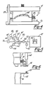
- FIGs 2 through 4 depict the major steps in the sequence of molding operations employed while carrying out the process of the present invention.
- a compression die set 10 has an upper moveable die 12 mounted on a moveable upper platen 14 and a lower fixed die 16 mounted on a fixed bed 18.
- the upper and lower dies 12, 16 are complementary and form a mold in the closed position.
- the upper and lower dies 12, 16 slideably mate along complementary vertical surfaces 20, 22 when the dies nest in a telescoping manner into the semi-closed and closed positions as shown in Figs. 3 and 4.
- the upper die 12 moves vertically relative to the fixed die 16 under the action of an actuator means 24 such as a hydraulic pneumatic actuator attached to a fixed upper platen 26 generally acting through a ram or rams attached to the moveable upper platen 14.
- the upper die 12 and associated moveable platen 14 move vertically along fixed vertical guide members 28 which maintain the dies in alignment.
- the lower end of guide 28 is rigidly mounted in the fixed lower bed 18.
- the dies 12, 16 have a vacuum seal 30 associated therewith.
- the seal portion attached to upper die 12 comprises an L-shaped bracket member 32 having a vertical leg 34 attached to the upper die and a horizontal leg 36 extending outward perpendicularly from the upper die.
- the L-shaped bracket has a tubular member 38 attached.
- a lower sealing means comprising a horizontally disposed shelf 40 extending perpendicularly away from lower die 16 and a raised pointed bead disposed on the shelf 40, the bead being adapted to engage the tube 38.
- the bead 42 will engage the tube 38 at an intermediate position, as shown in Fig. 3, before the dies are fully closed to form a sealed vacuum chamber 47 of which mold cavity 46 within the die set 10 is a part.
- the tubing diameter is large enough to form the seal before the molding compound 44 flows to fill the mold but there is sufficient travel allowed by the seal that the dies can be fully closed without seal damage.
- a piece of sheet molding compound 44 is placed on or in one of the dies when the dies are fully open. With the dies 12, 16 in the closed compression molding position shown in Fig. 4, the sheet molding compound 44 located within the cavity will slowly spread to fill the mold cavity 46 formed between the upper and lower dies.
- the dies are heated by steam, oil or other heating means in order to provide sufficient energy to cure the resin present in the sheet molding compound to a hard thermoset condition.
- the first step of any compression molding process is the provision of a die and cure base step 48 associated with a press suitable for applying the compressive force necessary to cause the sheet molding compound (SMC) to spread within the mold cavity as the mold is closed.
- the die is generally started in an open position step 50 with sufficient space between dies to allow the desired quantity of sheet molding compound, normally disposed as one or more sheets to be placed between the molds - step 52.
- the compound placed in the mold need not be formed in a rectangular shape and may have a configuration when viewed from the top like a dog bone or other configuration dictated by the flow of material within the die. Shaped charges are frequently used in order to equalize the time it takes for compound flowing from the charge to reach the outer portions of the mold.
- the die set 10 is closed to an evacuation position step 54 where the vacuum seal 30 is engaged and the interior cavity 46 of the die set is substantially sealed from the atmosphere as part of a vacuum chamber 47. This position will be reached before the upper die 12 contacts the SMC.
- the plastic flow is primarily in a substantially reduced pressure environment maintained within the vacuum chamber 47.
- the vacuum chamber 47 is evacuated in step 56 to the desired operating pressure.
- pressures will be reduced in the die cavity to approximately less than 7 inches of mercury absolute prior to final molding and curing of the sheet molding compound. Since many sheet molding compounds contain a quantity of low molecular weight monomeric or polymeric materials used as solvents, reactants, cross-linkers, or catalysts, it is desirable to minimize the SMC's exposure time to the reduced pressure prior to the molding and curing of the compound. Minimizing the exposure time will minimize the amount of low molecular weight constituents that are withdrawn from the body of the sheet molding compound by the reduced pressure. The vaporization of low molecular weight compounds in reduced pressure atmospheres is well known and further discussion is not necessary.
- polyester compounds having low shrink characteristics contain a certain amount of styrene monomer in addition to the primary polyester reactants and a thermoplastic material. Withdrawing excessive amounts of styrene from the surface of the part will result in macro porosity and possible discoloration of the parts. Therefore, where polyester resins are used, it is desired to limit the evacuation time of the vacuum chamber to no more than 20 seconds.
- the die is closed to its curing position in step 58 causing the sheet molding compound to spread and fill the mold cavity.
- the press is maintained in the closed curing position during step 60 with the pressure continuously being applied to insure that the presssure is uniformly distributed throughout the sheet molding compound. Simultaneously heat is applied to the dies in order to cause chemical reaction between the constituents of the thermosetting resin forming a hard thermoset material.
- the thermoset resin consolidates and holds the fibrous reinforcement in a rigid consolidated condition.
- the vacuum chamber 47 is returned to atmospheric pressure when the die has fully closed as shown in Fig. 4 since vacuum is not necessary and indeed may be harmful once the material has spread to completely fill the die cavity.
- Fig. 5 a schematic diagram of the die cavity 46, vacuum chamber 47 and associated vacuum apparatus 48.
- the vacuum apparatus has storage tanks, a vacuum pump and a plurality of valves.
- the die cavity 46 represents the schematic mold or die set, such as that shown in Figs. 3 and 4 located within vacuum chamber 47, which has a vacuum line 50 emanating from the interior of the chamber 47.
- the vacuum line 50 has an atmospheric exposure valve 52 attached to the vacuum line, the valve being operable between a first open position allowing atmospheric air to enter the valve in the vacuum line and a second closed position blocking the movement of air from the atmosphere into the vacuum line.
- a vacuum line control valve 54 is disposed in the vacuum line 50 between the atmospheric exposure valve 52 and a vacuum pump 56 and associated vacuum storage tanks 58. In the open position, vacuum valve 54 connects the vacuum pump 56 and associated vacuum storage tanks 58 to the vacuum line 50. In the closed position, vacuum line valve 54 isolates the pump and its associated storage tanks 58 from the remainder of the system.
- Three vacuum tanks 58 are shown separately connected to the terminus of the vacuum line by means of secondary vacuum lines 60 having secondary vacuum valve members disposed therein.
- the secondary vacuum valve 62 In the open position, the secondary vacuum valve 62 will expose the vacuum line to the vacuum present within an associated vacuum storage tank 58 and in the closed position will isolate the associated vacuum tank from the remainder of the system.
- the vacuum pump 56 is shown permanently connected to the terminus of the vacuum line 50.
- the vacuum pumps contemplated in the use of this invention can be positive displacement rotary vanes with an oil seal and water cooling. Such pumps are standard and well known in the art. Other forms of vacuum pumps can also be used.
- the vacuum tanks or vacuum surge tanks 58 used can be standard water or propane type tanks, said tanks having sufficient strength to withstand atmospheric pressure when the interior of the chamber has been evacuated to approximately 7 inches of mercury absolute.
- the atmospheric valve 52 will close and the vacuum line valve 54 will open exposing the interior of the mold cavity to the pumping action of the vacuum pump 56.
- a vacuum tank valve 62 will open for a short period of time, for example approximately 1 to 4 seconds and then close entrapping a substantial quantity of air contained in the vacuum chamber 47.
- a second vacuum tank valve will open for approximately 1 to 4 seconds withdrawing a substantial portion of the remaining atmosphere contained in the vacuum chamber 47 into the second associated vacuum tank at which time the second valve will close and a third valve will open exposing the vacuum chamber 47 to the rapid withdrawal action of the third associated vacuum tank.
- the vacuum pump will continue to pump the die cavity 46 until the desired reduced pressure is reached at which time the die will close to the pressing or part forming position shown in Fig. 4.
- the vacuum line valve 54 will close isolating the vacuum pump and associated tanks from the vacuum system and the atmospheric valve 52 will open allowing atmospheric pressure to flow back into the vacuum chamber 47.
- the vacuum tank valves 62 will open and the vacuum pump 56 will empty the vacuum tanks for the next molding cycle.
- the volume of the tanks to be used will depend on the volume of the die cavity when the mold is in the evacuating position.
- Using a vacuum tank having a volume approximately equal to the vacuum chamber to he evacuated will result in reducing the pressure in the vacuum chamber by a factor of approximately one-half each time an evacuated vacuum tank is exposed to the system.
- three tanks it is possible to reduce the pressure in the die cavity to about on-eighth of the beginning pressure in a matter of approximately 3 to 12 seconds. If greater reduction is necessary, use of larger chambers or more chambers is possible.
- a further way in which to reduce the amount of gas which must be removed from the vacuum chamber in order to achieve the desired pressure is to reduce its internal volume. Because the vacuum seal 30 is disposed about the periphery of the die, the vacuum chamber's volume which is contained within the vacuum seal can represent a considerable volume. This is especially true since the seal 30 must be shaped so as to allow it to function within the press necessitating certain compromises with respect to the shape of the seal and its location on the die set. Portions of the vacuum chamber which are not subjected to compression during the molding cycle, can be completely or partially filled with closed cell foam material which effectively reduces the volume to be evacuated during the evacuation cycle.
- the system has used three vacuum tanks. More vacuum tanks may be used if desired, however, vacuum tanks in excess of approximately four or five represent a substantial number of operations necessary to evacuate the vacuum chamber and the use of more than three tanks would generally not be desirable from a production standpoint.
- Use of only a single tank equal in volume to the space to be evacuated within the die cavity results in reducing the pressure by a factor of only one-half and has been found that the use of a plurality of tanks provides the desired rapid evacuation in the vacuum chamber without undue complexity of machinery and control mechanisms.
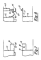
- Figs. 6, 7 and 8 show additional seal configurations useful in the practice of this invention.
- the exterior of upper die 12 has been finished to a smooth parallel condition.
- a moveable ring 64 is mounted on a horizontal arm 66 which extends radially inward from an air cylinder 68 mounted to the press frame (not shown).
- the moveable ring 64 has a wiper blade and seal 70 mounted in a position to contact the side wall of die 12.
- the lower die exterior has an L-shaped (in cross-section) collar 72 attached thereto with one flange extending perpendicularly outward from the die wall.
- a strip of tubing 73 such as silicone tubing is disposed on the upper surface of the collar where it is contacted by a horizontally extending flange 74 of moveable ring 64.
- the flange 74 will contact the tube 73 when the dies are closed to the evacuating position.
- Fig. 7 shows a sealing means formed of two complementary elastomeric members 76 and 78 disposed about the periphery of the upper die 12 and base 16.
- sealing member 76 has a lip 80 depending therefrom toward the second sealing member 78.
- the second sealing member has a complementary channel 82 adapted to receive the lip 80 to form a seal.
- Fig. 8 shows a seal means similar to Fig. 6 except moveable ring 64 has a flexible diaphragm 84 sealing the ring to the moveable upper die.
- the outer periphery of the diaphragm is attached to the moveable ring and the inner edge of the diaphragm is attached to the upper die.
Landscapes
- Engineering & Computer Science (AREA)
- Mechanical Engineering (AREA)
- Chemical & Material Sciences (AREA)
- Composite Materials (AREA)
- Casting Or Compression Moulding Of Plastics Or The Like (AREA)
- Press Drives And Press Lines (AREA)
- Moulding By Coating Moulds (AREA)
- Processing And Handling Of Plastics And Other Materials For Molding In General (AREA)
Priority Applications (1)
| Application Number | Priority Date | Filing Date | Title |
|---|---|---|---|
| AT84901906T ATE66404T1 (de) | 1983-04-25 | 1984-04-25 | Vorrichtung zum pressformen. |
Applications Claiming Priority (2)
| Application Number | Priority Date | Filing Date | Title |
|---|---|---|---|
| US488494 | 1983-04-25 | ||
| US06/488,494 US4488862A (en) | 1983-04-25 | 1983-04-25 | Compression molding apparatus having vacuum chamber |
Publications (3)
| Publication Number | Publication Date |
|---|---|
| EP0142530A1 EP0142530A1 (en) | 1985-05-29 |
| EP0142530A4 EP0142530A4 (en) | 1987-10-27 |
| EP0142530B1 true EP0142530B1 (en) | 1991-08-21 |
Family
ID=23939889
Family Applications (1)
| Application Number | Title | Priority Date | Filing Date |
|---|---|---|---|
| EP84901906A Expired - Lifetime EP0142530B1 (en) | 1983-04-25 | 1984-04-25 | Apparatus for compression molding |
Country Status (8)
| Country | Link |
|---|---|
| US (1) | US4488862A (enExample) |
| EP (1) | EP0142530B1 (enExample) |
| JP (2) | JPS60501153A (enExample) |
| AU (1) | AU568853B2 (enExample) |
| BR (1) | BR8406601A (enExample) |
| CA (1) | CA1217017A (enExample) |
| DE (1) | DE3484954D1 (enExample) |
| WO (1) | WO1984004273A1 (enExample) |
Families Citing this family (40)
| Publication number | Priority date | Publication date | Assignee | Title |
|---|---|---|---|---|
| US4855097A (en) * | 1983-04-25 | 1989-08-08 | The Budd Company | Compression molding a charge using vacuum |
| US4612149A (en) * | 1983-04-25 | 1986-09-16 | The Budd Company | Compression molding a charge using vacuum |
| WO1986001174A1 (en) * | 1984-08-07 | 1986-02-27 | Richard Silvester | Thrust augmenter |
| CA1267763A (en) * | 1986-03-19 | 1990-04-17 | Kenneth A. Iseler | Vacuum compression molding method using preheated charge |
| EP0299611A1 (en) * | 1987-06-05 | 1989-01-18 | Takeda Chemical Industries, Ltd. | Compression molding apparatus and method |
| US4867924A (en) * | 1988-04-22 | 1989-09-19 | The Budd Company | Method and apparatus for compression molding under vacuum |
| US4959189A (en) * | 1988-09-26 | 1990-09-25 | E. I. Du Pont De Nemours And Company | Process for forming a composite structure of thermoplastic polymer and sheet molding compound |
| US5001000A (en) * | 1988-09-26 | 1991-03-19 | E. I. Du Pont De Nemours And Company | Process for forming a composite structure of thermoplastic polymer and sheet molding compound |
| US5000997A (en) * | 1989-02-06 | 1991-03-19 | The Budd Company | Method for making a painted part and part made thereby |
| US5268400A (en) * | 1990-07-19 | 1993-12-07 | The Budd Company | Flexible sheet molding compound and method of making the same |
| US5100935A (en) * | 1990-07-19 | 1992-03-31 | The Budd Company | Flexible sheet molding compound and method of making the same |
| US5298212A (en) * | 1991-01-16 | 1994-03-29 | Surface Technologies, Inc. | Method for forming a laminated substrate |
| GB2272397A (en) * | 1992-10-14 | 1994-05-18 | Lotus Car | Moulding method and apparatus |
| ES2108602B1 (es) * | 1994-01-19 | 1998-07-16 | Hispano Mecano Electrica Sa | Perfeccionamientos en los procedimientos para moldeo de poliester y similares. |
| US5753164A (en) * | 1995-08-30 | 1998-05-19 | The Budd Company | Automated thermoset molding method |
| US6106274A (en) * | 1995-08-30 | 2000-08-22 | The Budd Company | Molding apparatus with charge overflow |
| DE19648844C1 (de) * | 1996-11-26 | 1997-09-18 | Jenoptik Jena Gmbh | Einrichtung und Verfahren zur Abformung mikrosystemtechnischer Strukturen |
| US6146578A (en) * | 1997-10-09 | 2000-11-14 | Lear Corporation | Method for molding headliners |
| US6416841B1 (en) | 1997-12-10 | 2002-07-09 | Pechiney Emballage Flexible Europe | Tear tape for plastic packaging |
| US6264454B1 (en) | 1998-03-11 | 2001-07-24 | The Budd Company | Wrapped SMC charge method and apparatus |
| US6103150A (en) * | 1998-03-11 | 2000-08-15 | The Budd Company | Molding overflow feedback method |
| US6103032A (en) * | 1998-04-24 | 2000-08-15 | The Budd Company | Sheet molding compound manufacturing improvements |
| US6119750A (en) * | 1998-04-24 | 2000-09-19 | The Budd Company | Sheet molding compound manufacturing improvements |
| US6533976B1 (en) * | 2000-03-07 | 2003-03-18 | Northrop Grumman Corporation | Method of fabricating ceramic matrix composites employing a vacuum mold procedure |
| US6805546B2 (en) * | 2001-10-24 | 2004-10-19 | Thyssenkrupp Budd Company | Vacuum assisted molding apparatus |
| WO2005032781A1 (en) * | 2003-10-07 | 2005-04-14 | Vertech Hume Pty Ltd | Vertical moulding of long concrete articles |
| US8127691B2 (en) * | 2004-03-03 | 2012-03-06 | Fitzpatrick Technologies, Llc | SMC pallet |
| US20060081158A1 (en) * | 2004-10-19 | 2006-04-20 | Fitzpatrick Technologies, L.L.C. | Pultrusion pallet |
| US20060220273A1 (en) * | 2005-03-29 | 2006-10-05 | Armstrong Bradford D | Process for compression moulding liquid resins with structural reinforcements |
| US20070017422A1 (en) * | 2005-07-19 | 2007-01-25 | Fitzpatrick Technologies, Llc | Pallet with composite components |
| US20070017423A1 (en) * | 2005-07-19 | 2007-01-25 | Ingham Terry L | Pallet With Recycled Components |
| US7915089B2 (en) * | 2007-04-10 | 2011-03-29 | Infineon Technologies Ag | Encapsulation method |
| US8261673B2 (en) * | 2007-09-26 | 2012-09-11 | Fitzpatrick Technologies | Pallet with lead board |
| JP4578517B2 (ja) * | 2007-12-26 | 2010-11-10 | Scivax株式会社 | インプリント装置およびインプリント方法 |
| US7968042B2 (en) * | 2008-04-16 | 2011-06-28 | Aptina Imaging Corporation | Method and apparatus for step-and-repeat molding |
| DE102012110307B4 (de) * | 2012-10-29 | 2020-01-23 | Kraussmaffei Technologies Gmbh | Verfahren zur Herstellung von Verbundmaterial-Bauteilen aus Kunststoff durch Hochdruck-Harztransferpressen und zugehöriges Hochdruck-Harztransferpressen-Werkzeug |
| CN103963318B (zh) | 2013-01-29 | 2019-08-09 | 康廷南拓结构塑料有限公司 | 热固性片状制品的真空成形方法 |
| EP2960036A1 (en) * | 2014-06-26 | 2015-12-30 | TCTech Sweden AB | Method and device for embossing/pressing |
| GB201610865D0 (en) * | 2016-06-22 | 2016-08-03 | Composite Tech And Applications Ltd | An apparatus for manufacturing a composite component |
| CN107243553A (zh) * | 2017-06-29 | 2017-10-13 | 奇瑞汽车股份有限公司 | 一种用于解决冲压件变形以及气孔坑的模具结构 |
Family Cites Families (17)
| Publication number | Priority date | Publication date | Assignee | Title |
|---|---|---|---|---|
| US2452382A (en) * | 1945-04-30 | 1948-10-26 | Emmet S Long | Apparatus for molding rubber and plastic materials |
| FR1241907A (fr) * | 1958-11-19 | 1960-09-23 | Straumann Inst Ag | Appareillage pour traitements thermiques sous vide poussé |
| US3504070A (en) * | 1968-02-19 | 1970-03-31 | Comet Ind | Vacuum forming method and apparatus |
| US3871060A (en) * | 1971-12-29 | 1975-03-18 | Ladney M Jr | Method of constructing mold for forming plastic foam parts |
| US3959434A (en) * | 1972-07-17 | 1976-05-25 | M. Lowenstein & Sons, Inc. | Three dimensional decorative material and process for producing same |
| FR2197644A1 (en) * | 1972-08-31 | 1974-03-29 | Ferte Albert | Sterilising autoclave vacuum system - reduces sterilising cycle time and speeds evacuation of air from vessel |
| US3840239A (en) * | 1972-10-26 | 1974-10-08 | Gen Tire & Rubber Co | Compression molding in a vacuum and seal for use therein |
| IT1030195B (it) * | 1975-02-20 | 1979-03-30 | Marocco G | Procedimento ed apparecchiatura per la produzione di blocci di marmo e simili pietre naturali |
| US4076788A (en) * | 1976-12-02 | 1978-02-28 | General Motors Corporation | Mold coating of freshly molded articles |
| JPS5597929A (en) * | 1979-01-19 | 1980-07-25 | Matsushita Electric Ind Co Ltd | Production of flat plate-shaped body |
| JPS55158952A (en) * | 1979-05-30 | 1980-12-10 | Ootake Kikai Kogyo Kk | Moldng and vulcanizing of rubber |
| US4267142A (en) * | 1979-10-22 | 1981-05-12 | Lankheet Jay A | Reinforced resin molding method and apparatus |
| US4374080A (en) * | 1981-01-13 | 1983-02-15 | Indy Electronics, Inc. | Method and apparatus for encapsulation casting |
| US4416841A (en) * | 1981-03-11 | 1983-11-22 | Corea John E | Method for centrifugal casting of thermosetting plastics |
| JPS57187212A (en) * | 1981-05-12 | 1982-11-17 | Akira Washida | Vacuum molding apparatus |
| JPS581522A (ja) * | 1981-06-25 | 1983-01-06 | Sekisui Chem Co Ltd | Frpの製造方法 |
| JPS6036417Y2 (ja) * | 1982-11-22 | 1985-10-29 | 株式会社内藤製作所 | 加硫成形装置 |
-
1983
- 1983-04-25 US US06/488,494 patent/US4488862A/en not_active Expired - Lifetime
-
1984
- 1984-04-25 JP JP59501845A patent/JPS60501153A/ja active Granted
- 1984-04-25 DE DE8484901906T patent/DE3484954D1/de not_active Expired - Lifetime
- 1984-04-25 WO PCT/US1984/000627 patent/WO1984004273A1/en not_active Ceased
- 1984-04-25 EP EP84901906A patent/EP0142530B1/en not_active Expired - Lifetime
- 1984-04-25 AU AU28630/84A patent/AU568853B2/en not_active Ceased
- 1984-04-25 CA CA000452779A patent/CA1217017A/en not_active Expired
- 1984-04-25 BR BR8406601A patent/BR8406601A/pt not_active IP Right Cessation
-
1991
- 1991-04-02 JP JP3069705A patent/JPH0651310B2/ja not_active Expired - Lifetime
Also Published As
| Publication number | Publication date |
|---|---|
| AU2863084A (en) | 1984-11-19 |
| WO1984004273A1 (en) | 1984-11-08 |
| JPH04219218A (ja) | 1992-08-10 |
| EP0142530A4 (en) | 1987-10-27 |
| DE3484954D1 (de) | 1991-09-26 |
| CA1217017A (en) | 1987-01-27 |
| JPH0651310B2 (ja) | 1994-07-06 |
| EP0142530A1 (en) | 1985-05-29 |
| AU568853B2 (en) | 1988-01-14 |
| JPH04448B2 (enExample) | 1992-01-07 |
| JPS60501153A (ja) | 1985-07-25 |
| US4488862A (en) | 1984-12-18 |
| BR8406601A (pt) | 1985-03-12 |
Similar Documents
| Publication | Publication Date | Title |
|---|---|---|
| EP0142530B1 (en) | Apparatus for compression molding | |
| US4551085A (en) | Compression molding apparatus having vacuum chamber | |
| EP0189471B1 (en) | Compression molding a charge using vacuum | |
| US5130071A (en) | Vacuum compression molding method using preheated charge | |
| US3135640A (en) | Process of and an apparatus for manufacturing hollow articles from reinforced synthetic resins | |
| US2441097A (en) | Plastics molding apparatus | |
| US3267517A (en) | Apparatus for molding hardenable plastics in a vacuum | |
| US4855097A (en) | Compression molding a charge using vacuum | |
| AU636418B2 (en) | Reaction injection molding apparatus for forming fiber-resin forced molded article | |
| CA2170106C (en) | Resin transfer molding process | |
| US6929770B2 (en) | Mandrel-assisted resin transfer molding process employing resin outflow perimeter channel between male and female mold elements | |
| US20030075840A1 (en) | Vacuum assisted molding | |
| JP3027607B2 (ja) | 合成樹脂から成る大きな物体の真空成形方法 | |
| CA1217018A (en) | Compression molding apparatus having vacuum chamber | |
| US3368239A (en) | Apparatus for molding impregnated glass fiber articles | |
| CN1009181B (zh) | 一种空心体的制造方法 | |
| US3442998A (en) | Method for making impregnated fiber articles | |
| EP0553486A1 (en) | Tooling and process for moulding polymeric materials in the liquid state | |
| CS223857B2 (en) | Method of casting and facility for executing the same | |
| CN221187586U (zh) | 一种碳纤维模压真空导流装置 | |
| CN212241915U (zh) | 一种方便注塑的汽车上装饰板模具 | |
| EP1645387A1 (en) | System and method for gas suction in a mould for foaming | |
| JPH02204013A (ja) | 成形型および成形方法 | |
| JPS61130013A (ja) | コンプレツシヨンモ−ルド装置 | |
| ES2070074A1 (es) | Perfeccionamientos en la fabricacion de elementos de recipiente para fluidos a presion. |
Legal Events
| Date | Code | Title | Description |
|---|---|---|---|
| PUAI | Public reference made under article 153(3) epc to a published international application that has entered the european phase |
Free format text: ORIGINAL CODE: 0009012 |
|
| 17P | Request for examination filed |
Effective date: 19850125 |
|
| AK | Designated contracting states |
Designated state(s): AT BE CH DE FR GB LI LU NL SE |
|
| A4 | Supplementary search report drawn up and despatched |
Effective date: 19871027 |
|
| 17Q | First examination report despatched |
Effective date: 19890309 |
|
| GRAA | (expected) grant |
Free format text: ORIGINAL CODE: 0009210 |
|
| AK | Designated contracting states |
Kind code of ref document: B1 Designated state(s): AT BE CH DE FR GB LI LU NL SE |
|
| PG25 | Lapsed in a contracting state [announced via postgrant information from national office to epo] |
Ref country code: LI Effective date: 19910821 Ref country code: CH Effective date: 19910821 Ref country code: BE Effective date: 19910821 Ref country code: AT Effective date: 19910821 |
|
| REF | Corresponds to: |
Ref document number: 66404 Country of ref document: AT Date of ref document: 19910915 Kind code of ref document: T |
|
| REF | Corresponds to: |
Ref document number: 3484954 Country of ref document: DE Date of ref document: 19910926 |
|
| REG | Reference to a national code |
Ref country code: CH Ref legal event code: PL |
|
| ET | Fr: translation filed | ||
| PG25 | Lapsed in a contracting state [announced via postgrant information from national office to epo] |
Ref country code: LU Free format text: LAPSE BECAUSE OF NON-PAYMENT OF DUE FEES Effective date: 19920430 |
|
| PLBE | No opposition filed within time limit |
Free format text: ORIGINAL CODE: 0009261 |
|
| STAA | Information on the status of an ep patent application or granted ep patent |
Free format text: STATUS: NO OPPOSITION FILED WITHIN TIME LIMIT |
|
| 26N | No opposition filed | ||
| EAL | Se: european patent in force in sweden |
Ref document number: 84901906.2 |
|
| PGFP | Annual fee paid to national office [announced via postgrant information from national office to epo] |
Ref country code: FR Payment date: 20010330 Year of fee payment: 18 |
|
| PGFP | Annual fee paid to national office [announced via postgrant information from national office to epo] |
Ref country code: SE Payment date: 20010402 Year of fee payment: 18 Ref country code: DE Payment date: 20010402 Year of fee payment: 18 |
|
| PGFP | Annual fee paid to national office [announced via postgrant information from national office to epo] |
Ref country code: GB Payment date: 20010403 Year of fee payment: 18 |
|
| PGFP | Annual fee paid to national office [announced via postgrant information from national office to epo] |
Ref country code: NL Payment date: 20010412 Year of fee payment: 18 |
|
| REG | Reference to a national code |
Ref country code: GB Ref legal event code: IF02 |
|
| PG25 | Lapsed in a contracting state [announced via postgrant information from national office to epo] |
Ref country code: GB Free format text: LAPSE BECAUSE OF NON-PAYMENT OF DUE FEES Effective date: 20020425 |
|
| PG25 | Lapsed in a contracting state [announced via postgrant information from national office to epo] |
Ref country code: SE Free format text: LAPSE BECAUSE OF NON-PAYMENT OF DUE FEES Effective date: 20020426 |
|
| PG25 | Lapsed in a contracting state [announced via postgrant information from national office to epo] |
Ref country code: NL Free format text: LAPSE BECAUSE OF NON-PAYMENT OF DUE FEES Effective date: 20021101 Ref country code: DE Free format text: LAPSE BECAUSE OF NON-PAYMENT OF DUE FEES Effective date: 20021101 |
|
| EUG | Se: european patent has lapsed |
Ref document number: 84901906.2 |
|
| GBPC | Gb: european patent ceased through non-payment of renewal fee |
Effective date: 20020425 |
|
| PG25 | Lapsed in a contracting state [announced via postgrant information from national office to epo] |
Ref country code: FR Free format text: LAPSE BECAUSE OF NON-PAYMENT OF DUE FEES Effective date: 20021231 |
|
| NLV4 | Nl: lapsed or anulled due to non-payment of the annual fee |
Effective date: 20021101 |
|
| REG | Reference to a national code |
Ref country code: FR Ref legal event code: ST |