EP0140992B1 - Elément transducteur, méthode de sa fabrication et utilisation pour un capteur de pression - Google Patents
Elément transducteur, méthode de sa fabrication et utilisation pour un capteur de pression Download PDFInfo
- Publication number
- EP0140992B1 EP0140992B1 EP83111227A EP83111227A EP0140992B1 EP 0140992 B1 EP0140992 B1 EP 0140992B1 EP 83111227 A EP83111227 A EP 83111227A EP 83111227 A EP83111227 A EP 83111227A EP 0140992 B1 EP0140992 B1 EP 0140992B1
- Authority
- EP
- European Patent Office
- Prior art keywords
- plate
- diaphragm
- insulating
- transduction element
- base plate
- Prior art date
- Legal status (The legal status is an assumption and is not a legal conclusion. Google has not performed a legal analysis and makes no representation as to the accuracy of the status listed.)
- Expired
Links
Images

Classifications
-
- G—PHYSICS
- G01—MEASURING; TESTING
- G01L—MEASURING FORCE, STRESS, TORQUE, WORK, MECHANICAL POWER, MECHANICAL EFFICIENCY, OR FLUID PRESSURE
- G01L19/00—Details of, or accessories for, apparatus for measuring steady or quasi-steady pressure of a fluent medium insofar as such details or accessories are not special to particular types of pressure gauges
- G01L19/0061—Electrical connection means
- G01L19/0084—Electrical connection means to the outside of the housing
-
- G—PHYSICS
- G01—MEASURING; TESTING
- G01L—MEASURING FORCE, STRESS, TORQUE, WORK, MECHANICAL POWER, MECHANICAL EFFICIENCY, OR FLUID PRESSURE
- G01L19/00—Details of, or accessories for, apparatus for measuring steady or quasi-steady pressure of a fluent medium insofar as such details or accessories are not special to particular types of pressure gauges
- G01L19/06—Means for preventing overload or deleterious influence of the measured medium on the measuring device or vice versa
- G01L19/0627—Protection against aggressive medium in general
- G01L19/0645—Protection against aggressive medium in general using isolation membranes, specially adapted for protection
-
- G—PHYSICS
- G01—MEASURING; TESTING
- G01L—MEASURING FORCE, STRESS, TORQUE, WORK, MECHANICAL POWER, MECHANICAL EFFICIENCY, OR FLUID PRESSURE
- G01L19/00—Details of, or accessories for, apparatus for measuring steady or quasi-steady pressure of a fluent medium insofar as such details or accessories are not special to particular types of pressure gauges
- G01L19/14—Housings
- G01L19/147—Details about the mounting of the sensor to support or covering means
Definitions
- the invention relates to a transducer element with a membrane plate made of semiconductor material having at least one membrane region with at least one piezoresistor and an insulating plate on which the membrane plate is fastened.
- the invention further relates to methods for producing the transducer element and a pressure sensor using the transducer element.
- the measuring element of such pressure transducers is a plate, preferably made of silicon (Si) single crystal, arranged on an insulating substrate, such as glass, on which an elastic membrane region is formed, which is deflected under the measuring pressure acting on it.
- the resistors are attached or diffused into the membrane area, which are connected to full or half measuring bridges in a known manner.
- Silicon as a single crystal material has excellent mechanical properties in that it shows practically no signs of aging and wear. Silicon is therefore an ideal semiconductor material for the formation of the membrane plates, especially since it can be machined with high precision mechanically or chemically and has particularly good electrical properties.
- the main disadvantage of silicon is the temperature expansion coefficient, which is four to six times lower than that of the steels commonly used for the pressure transducer housing, in particular the austenitic corrosion-resistant steels. Therefore, temperature changes can easily lead to tension and warping of the Si membrane plates attached to such steels, which in turn e.g. Zero deviations can result.
- a piezoresistive pressure transducer based on a transducer element in which the Si membrane plate by an anodic connection, which requires heating in the temperature range of 360 ° C-500 ° C, on an insulating glass plate is attached. Since glass has a higher coefficient of expansion than silicon, the laminate from the two plates tends to tighten during cooling by placing the Si membrane plate laterally under compressive stress. In extreme cases, this can cause the membrane to "fold over" from one stable position to another (sleeve cover effect). Such instability, even when the extreme case is not reached, changes the slope or calibration curve in a highly undesirable manner and is the cause of various deviations from the linearity. In addition, the zero point is strongly dependent on the temperature.
- a piezoresistive pressure transducer based on a Si membrane plate is also known, which is attached to a mounting plate made of an Fe-Ni alloy via a thick soft solder layer.
- Soft solders have significantly higher coefficients of expansion than silicon and therefore also cause tensioning of the membrane plate when the temperature changes.
- such pressure transducers are not suitable for precision measurements.
- GB-A-20 80 541 describes a sensor with an Si membrane plate attached to one side of a gas plate.
- a tubular holder made of an Fe-Ni alloy is attached to the opposite side of the glass plate.
- the thermal expansion coefficients of adjacent components are matched to one another. Although it can be achieved with a certain composition of the Fe-Ni alloy that its thermal expansion coefficient largely corresponds to that of Pyrex glass, a perfect match cannot be achieved.
- pressure transducers can be produced in which there is no need to crack during the anodic connection, provided that certain upper temperature limit values are not exceeded, but the remaining differences in the coefficients of thermal expansion have the consequence that none with regard to the zero point constancy and measuring accuracy substantial improvement over other known arrangements can be achieved.
- the invention is based on the object of creating a converter element of the type mentioned at the outset which can be produced inexpensively and with high precision and in which temperature changes over a wide temperature range only go or none Result in tension in the measuring membrane.
- a base plate is attached to the surface of the insulating plate facing away from the membrane plates, which has a coefficient of thermal expansion which is essentially the same as that of the membrane plate and whose dimensions are matched to the dimensions of the membrane plate in such a way that the temperature change Deformation forces exerted by the membrane and base plate on the insulating plate are essentially the same in order to achieve a stress-symmetrical state.
- the deformation forces exerted by the two plates on the insulating plate are essentially the same sense; for example, if the temperature expansion coefficient of the semiconductor material is smaller than that of the insulation material, the temperature expansion coefficient of the material of the base plate should also be smaller than that of the insulation material.
- the base plate can also be anodically bonded to the insulator, or glass frits are used for bonding. Both methods require heating to 400 ° C to 500 ° C. In the event of a temperature change, the force effects of both plates bound to the insulator are in the same sense and support each other.
- a glass plate which is bound on one side to a silicon membrane plate and on the other side to a base plate also made of silicon, is prevented from thermally contracting when cooled from both sides and the force of the glass plate on the membrane plate is less than because there would be no base plate.
- the thermal effect of the force of the base plate on the glass plate causes the same tension during the cooling process, which continues and is maintained through weakening through the glass plate.
- the converter element according to the invention is therefore characterized in that temperature changes in a wide temperature range of at least 100 ° C. result in little to no change in the preload of the membrane parts.
- the pressure transducers equipped with the transducer element according to the invention are therefore distinguished by high accuracy, temperature independence of the sensitivity and zero point stability.
- the base plate and the membrane plate can consist of the same or different materials, provided that their thermal expansion coefficients are similar to that of the insulator or the membrane plates.
- the preferred material for the base and membrane plate is silicon, while the insulating plate is preferably made of a suitable glass material. This has among other things the advantage that the plates can be attached to each other by rigid anodic connections.
- the base plate can be made of a metallic material, e.g. an iron-nickel alloy with a similar coefficient of expansion.
- the base plate compensates for expansion between the insulating plate and the intermediate carrier, even if this should consist of a material with a higher coefficient of expansion than the material of the insulating plate.
- the connection of the base plate to the mushroom-shaped intermediate carrier can be an adhesive, a glass frit or a solder.
- a solderable surface coating can be provided on the intermediate carrier. Transducer elements with such intermediate carriers can therefore be soldered particularly economically on the mounting plates or brackets of the pressure transducers in the so-called batch process.
- the method for producing a transducer element of the type mentioned at the outset is characterized in that anodically connecting a water having a multiplicity of membrane regions from the semiconductor material and a plate substrate made of the insulating material, which cuts the laminate formed into units each having at least one membrane region, Manufacture base plates from a material with substantially the same coefficient of thermal expansion as the membrane plate and a dimension matched to the membrane plate of each unit, and attach a prefabricated base plate to the insulating plate of each unit, after which, when the temperature changes, those exerted by the base plate and membrane plate on the insulating plate Deformation forces to achieve a tension ymmetric state are substantially the same.
- the base plate is preferably attached to the insulating plate simultaneously in one and the same heat treatment process together with the attachment of the base plate to the holder of the receiver or to a mushroom-shaped intermediate carrier.
- the base plate is preferably connected to the insulating plate or the holder by glass frits, but an adhesive connection would also be possible.
- An alternative to the aforementioned method is characterized in that a plate substrate made of the insulating material arranged between a wafer having a plurality of membrane regions and made of the semiconductor material and a base wafer and anodically connected to the wafer, the base wafer being made of a material with essentially the same coefficient of thermal expansion as the membrane wafer and having a dimension matched to the membrane wafer, and so formed Laminates into units with at least one membrane area, according to which, when the temperature changes, the deformation forces exerted by the membrane and base plate of each unit on the insulating plate are essentially the same in order to achieve a stress-symmetrical state.
- the transducer element obtained can then be processed in a further step, e.g. be attached to a mounting plate or holder of the pressure transducer by gluing or by glass frit. Glass frits are the application of a glass powder to the surfaces to be joined and the subsequent melting of the glass.
- a pressure transducer using a transducer element of the aforementioned type is characterized in that the transducer element is attached directly or via an intermediate carrier fastened to the base plate to a holder arranged in the transducer housing.
- the attachment can be done by gluing, soldering or glass frit.
- the holder should preferably be connected to the transducer housing in an elastic manner.
- a particularly advantageous development of the invention is therefore characterized in that the holder is connected to the transducer housing via a stretch-elastic tubular part.
- the holder thus has an essentially U-shaped cross section. This not only elastically absorbs the thermal expansion of the transducer housing, but also provides the additional advantage that the sensitive glazing with which the electrical conductors that conduct the measurement signals to the outside are fastened in the holder is located far enough away from the point can be where the tubular part is welded to the transducer housing. This avoids harmful local overheating of the glazing.
- the tubular elastic part can be arranged on the same side of the holder as the transducer element. In this case, the posture with the transducer element on it is installed from below into the transducer housing. Therefore, before installing the bracket, a sealing membrane for a pressure transmission medium to be provided on the housing can be attached and checked for proper function.
- the elastic tubular part can also be arranged on the side of the posture facing away from the transducer element. This opens up the possibility of also allowing the pressure transmission medium to act laterally on the holder or the tubular part, so that the electrical conductors which are glazed in the holder are exposed to a lateral pressure. This prevents the electrical conductors from being pressed out of the glazing, in particular at high measuring pressures.
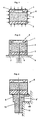
- the general reference numeral 8 shows a force-symmetrical or strain-compensated transducer element according to the invention, which is an upper membrane plate 1, a intermediate insulating plate 2 and a lower base plate 3 comprises.
- the membrane plate 1 consists of a semiconductor material, preferably silicon, in the central region of which a recess 4 is made from below, which thins the wall thickness of the plate 1 like a membrane.
- the membrane plate 1 has piezoresistors which can be diffused into or attached to the plate by known methods of semiconductor technology.
- the membrane plate 1 is fastened on the insulating plate 2 with its thick-walled edge region.
- the insulating plate 2 should consist of a material with a suitable coefficient of thermal expansion in relation to the membrane plate 1, which can also be easily connected to the membrane plate 1.
- Particularly suitable for the insulating plate 2 are glass materials, preferably borosilicate glasses, whose thermal expansion coefficient is lower than that of other glasses, but still higher than that of silicon.
- the base plate 3 can basically consist of any suitable material that has a coefficient of thermal expansion that is as low or lower as the material of the membrane plate 1. Silicon has proven to be suitable for the base plate 3.
- the plates 1 and 3 can be connected by known methods of semiconductor technology, with the anodic connection being preferred in particular because of its high strength and rigidity.
- the anodic connection technology is known to the person skilled in the art and therefore need not be explained in more detail.
- the base plate 3 can be advantageous to make the base plate 3 thicker than the membrane plate 1.
- lower stress peaks in the membrane plate 1 can be achieved by asymmetrical distribution of forces.
- the intermediate carrier 9, 9 ' which, in conjunction with a transducer element for relative pressure measurements, is also penetrated by a through-hole aligned with the bore 6, can have a solderable surface layer 11 on its shank region 10. This opens e.g. the possibility of simultaneously soldering a large number of intermediate carriers 9, 9 'with transducer elements 8 attached to them to a corresponding plurality of brackets 7 in the so-called batch process.
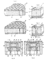
- the plate-shaped substrate 17, as indicated at 15, can be pierced.
- the two-layer laminate according to FIG. 4 has the advantage that the bonding zone 16 between the wafer 18 and the insulating substrate 17, which is preferably a glass plate, can easily be monitored optically. You can immediately see the zones that have entered into a perfect connection between the two plates. 4, units corresponding to one transducer element each with a membrane plate 1 and an insulating plate 2 according to FIG. 5 are e.g. cut using a diamond saw. A prefabricated base plate 3, as described in connection with Fig. 1, is then placed on each unit thus formed, e.g. fixed by a glass frit connection 14.
- the reference number 19 indicates connection points on the membrane plate 1 via which the electrical signal of the resistors can be taken off.
- the method shown in FIG. 6 differs from the method according to FIG. 5 in that a further wafer 20, from which the base plates 3 are formed, is applied to the side of the insulating substrate 17 opposite the wafer 18. Wafers 18 and 20 are connected to insulating substrate 17, preferably by anodic connections 16.
- a converter element cut out of the three-layer laminate according to FIG. 6 is shown in FIG. 7 and corresponds to the element which was explained in more detail in connection with FIGS. 1 and 2.
- the transducer element can be over an intermediate layer 5, e.g. a glass frit connection, can be fastened on the holder 7 of the sensor, or an adhesive can also be provided.
- FIG. 8 shows a pressure sensor with a symmetrical transducer element 8 according to FIG. 1.
- the transducer element 8 is attached or glued directly to the plate-shaped holder of the transducer via an intermediate layer 5.
- the holder 7 has bores in which electrical conductors 22 are cast in glass eyes 26.
- the electrical conductors 22 are connected to the connection points 19 of the resistors on the membrane plate 1 by wires 27 made of gold or aluminum.
- the holder 7 lies on an annular shoulder surface at an intermediate point of the sensor housing 32 and is hermetically connected to the sensor housing by a circumferential weld seam 24.
- the transducer element 8 is pressurized via a pressure transmission medium 25, which is preferably silicone oil.
- the pressure transmission medium essentially fills the space enclosed by the housing 32 above the holder 7, which, as shown, is sealed at the top by an elastic metal membrane 28 attached to the housing 32.
- a ring 21 made of a ceramic material is inserted in the housing.
- the bracket 7 is because of the better processing and the necessary through holes for the conductors 22 made of a non-corrosion-resistant steel with a temperature expansion coefficient that is smaller than the expansion coefficient of the austenitic steels preferably used for the housing of the pressure transducer.
- the holder carrying the transducer element is connected to the transducer housing 33 via a tubular elastic part 30.
- This stretch-elastic connection has the effect that thermal stresses have a significantly lower effect on the intermediate layer between the holder and the transducer element than is the case with the simple plate-shaped holder according to the embodiment according to FIG. 8.
- the elastic connection therefore makes another important contribution to the creation of piezoresistive pressure transducers for precision measurements, in which the measuring accuracy is essentially not affected by temperature changes.
- the tubular, elastic part 30 is molded on the same side as the transducer element 8 on the holder 7 and, as indicated at 31, is welded to a horizontal shoulder surface on the transducer housing 33 by means of butt welding on its free upper end face.
- the sensor according to FIG. 9 corresponds to that according to FIG. 8, so that reference can be made to this extent.
- 9 has the advantage that the Arrangement of holder 7 and transducer element 8 can be inserted from below into the housing 33 after the membrane 28 has been attached to the housing. The proper fastening and formation of the membrane 28 can therefore be checked before the holder 7 with the transducer element 8 is fastened to the housing 33 via the tubular part 30.
- Fig. 10 shows a pressure sensor with a holder 7, which has a recess on its upper side in which the transducer element 8 e.g. is attached by a layer 40 based on an epoxy resin.
- the tubular stretch-elastic part 30 protrudes from the lower side of the holder 7 facing away from the transducer element 8 and is butt-welded on its free end face to a shoulder surface on the sensor housing 39. Since the tubular part 30 extends away from the membrane 28, the arrangement from the holder 7 with the transducer element 8 attached to it must first be attached to the housing 39 before the membrane 28 can be installed.
- a plate 33 with compensation resistors 34 can also be fastened to a lower region of the transducer housing 39.
- the electrical conductors 22 are guided through the plate 33 via sliding bushes 37.
- Strands 36 of the electrical conductor 22 are used for signal discharge.
- the plate 33, the resistors 34 and the electrical conductors 22 can be embedded in a plastic compound 35, which is introduced in the lower region of the housing 39 as shown.
- FIG. 11 shows a pressure transducer for relative pressure measurements using an arrangement of transducer element and intermediate carrier, as shown in FIG. 3 on the right half of the drawing.
- the symmetrical transducer element 8 is fastened to the T-shaped intermediate carrier, which in turn is soldered with its shaft region 10 into a hole in the holder 7.
- a cement connection can also be provided.
- the holder 7 with the elastic tubular part 30 and the soldered arrangement of intermediate carrier and transducer element is inserted into the sensor housing 53 from below, after which the free upper end face of the tubular part 30 with an annular heel surface on the sensor housing 53 , as indicated at 31, butt-welded.
- the pressure supply to the underside of the membrane plate of the transducer element 8 required for the relative pressure measurement takes place via a tube 50 which is fastened to the shaft region 10 of the intermediate carrier and extends downwards out of the transducer.
- the length L of the tubular elastic part 30 can be selected according to the respective conditions, so that it is always ensured that the glass eyes 26 holding the electrical conductors 22 are not overheated by the welding at the point 31 and at the same time the tubular elastic part 30 is the desired one can have a stretch-compensating effect.
- the transducer shown in FIG. 11 essentially corresponds to the embodiment according to FIG. 9 and, with respect to the parts provided in the lower part of the transducer housing, to parts 33 to 37 in the embodiment according to FIG. 10, so that reference can be made here.
Landscapes
- Physics & Mathematics (AREA)
- General Physics & Mathematics (AREA)
- Chemical & Material Sciences (AREA)
- Analytical Chemistry (AREA)
- Measuring Fluid Pressure (AREA)
- Pressure Sensors (AREA)
- Transducers For Ultrasonic Waves (AREA)
Claims (18)
Priority Applications (5)
| Application Number | Priority Date | Filing Date | Title |
|---|---|---|---|
| AT83111227T ATE34613T1 (de) | 1983-11-10 | 1983-11-10 | Wandlerelement, verfahren zu seiner herstellung sowie verwendung fuer einen druckaufnehmer. |
| DE8383111227T DE3376760D1 (en) | 1983-11-10 | 1983-11-10 | Transducer element, method for its manufacture and its use in a pressure pick-up device |
| EP83111227A EP0140992B1 (fr) | 1983-11-10 | 1983-11-10 | Elément transducteur, méthode de sa fabrication et utilisation pour un capteur de pression |
| US06/645,262 US4675643A (en) | 1983-11-10 | 1984-08-29 | Pressure transducer utilizing a transduction element |
| JP59237407A JPS60167385A (ja) | 1983-11-10 | 1984-11-10 | トランスジユ−サ素子とその製造方法及びトランスジユ−サ素子を組み込んだ圧力トランスジユ−サ |
Applications Claiming Priority (1)
| Application Number | Priority Date | Filing Date | Title |
|---|---|---|---|
| EP83111227A EP0140992B1 (fr) | 1983-11-10 | 1983-11-10 | Elément transducteur, méthode de sa fabrication et utilisation pour un capteur de pression |
Publications (2)
| Publication Number | Publication Date |
|---|---|
| EP0140992A1 EP0140992A1 (fr) | 1985-05-15 |
| EP0140992B1 true EP0140992B1 (fr) | 1988-05-25 |
Family
ID=8190798
Family Applications (1)
| Application Number | Title | Priority Date | Filing Date |
|---|---|---|---|
| EP83111227A Expired EP0140992B1 (fr) | 1983-11-10 | 1983-11-10 | Elément transducteur, méthode de sa fabrication et utilisation pour un capteur de pression |
Country Status (5)
| Country | Link |
|---|---|
| US (1) | US4675643A (fr) |
| EP (1) | EP0140992B1 (fr) |
| JP (1) | JPS60167385A (fr) |
| AT (1) | ATE34613T1 (fr) |
| DE (1) | DE3376760D1 (fr) |
Families Citing this family (36)
| Publication number | Priority date | Publication date | Assignee | Title |
|---|---|---|---|---|
| EP0215140B1 (fr) * | 1985-09-11 | 1989-04-26 | Kunz, Manfred | Capteur de pression |
| DE3772514D1 (de) * | 1986-10-28 | 1991-10-02 | Sumitomo Electric Industries | Messverfahren fuer einen halbleiter-druckmessfuehler. |
| DE3777188D1 (de) * | 1987-11-27 | 1992-04-09 | Kristal Instr Ag | Messzelle, insbesondere fuer relativ- und differenzdruckmessungen. |
| US5000047A (en) * | 1988-03-29 | 1991-03-19 | Nippondenso Co., Ltd. | Pressure sensor |
| US4926155A (en) * | 1988-12-12 | 1990-05-15 | Johnson Service Company | Integrated circuit silicon pressure transducer package |
| US4930929A (en) * | 1989-09-26 | 1990-06-05 | Honeywell Inc. | Glass tube/stainless steel header interface for pressure sensor |
| KR930011091B1 (ko) * | 1990-06-08 | 1993-11-20 | 미쯔비시 덴끼 가부시끼가이샤 | 압력 센서 |
| US5421956A (en) * | 1991-11-20 | 1995-06-06 | Nippondenso Co., Ltd. | Method of fabricating an integrated pressure sensor |
| US5333505A (en) * | 1992-01-13 | 1994-08-02 | Mitsubishi Denki Kabushiki Kaisha | Semiconductor pressure sensor for use at high temperature and pressure and method of manufacturing same |
| DE4211816C2 (de) * | 1992-04-08 | 1995-08-31 | Danfoss As | Drucksensor |
| DE4321804A1 (de) * | 1993-06-30 | 1995-01-12 | Ranco Inc | Verfahren zur Herstellung von Kleinbauelementen |
| US5703296A (en) * | 1995-06-27 | 1997-12-30 | Delco Electronics Corp. | Pressure sensor having reduced hysteresis and enhanced electrical performance at low pressures |
| DE19612964A1 (de) * | 1996-04-01 | 1997-10-02 | Bosch Gmbh Robert | Drucksensor und Verfahren zur Herstellung eines Drucksensors |
| KR100432068B1 (ko) * | 1996-04-13 | 2004-09-08 | 로베르트 보쉬 게엠베하 | 압력센서 |
| JPH1130559A (ja) * | 1997-07-10 | 1999-02-02 | Fuji Koki Corp | 圧力センサ |
| US6311561B1 (en) | 1997-12-22 | 2001-11-06 | Rosemount Aerospace Inc. | Media compatible pressure sensor |
| US6076409A (en) * | 1997-12-22 | 2000-06-20 | Rosemount Aerospace, Inc. | Media compatible packages for pressure sensing devices |
| US6570485B1 (en) * | 2000-11-17 | 2003-05-27 | Honeywell International Inc. | Transducer packaging assembly for use in sensing unit subjected to high G forces |
| US7641864B2 (en) * | 2001-06-15 | 2010-01-05 | Avure Technologies Incorporated | Thermal sensor connector for pressure vessel |
| AU2003294666A1 (en) * | 2002-12-12 | 2004-06-30 | Danfoss A/S | A pressure sensor |
| JP2004198147A (ja) * | 2002-12-16 | 2004-07-15 | Toyoda Mach Works Ltd | 圧力センサ |
| US6883380B2 (en) * | 2003-05-16 | 2005-04-26 | Rosemount Inc | Pressure sensor capsule |
| JP2005037310A (ja) * | 2003-07-18 | 2005-02-10 | Fuji Koki Corp | 圧力センサ |
| US20060255669A1 (en) * | 2005-05-12 | 2006-11-16 | Remy International, Inc. | Flexible diode connection for pressfit bridge rectifier |
| US7458275B2 (en) * | 2007-03-15 | 2008-12-02 | Rosemount Inc. | Welded header for pressure transmitter |
| CN101960276B (zh) * | 2007-10-30 | 2013-07-03 | 阿自倍尔株式会社 | 压力传感器及其制造方法 |
| DE102008049143B4 (de) * | 2008-09-26 | 2012-08-16 | Intelligente Sensorsysteme Dresden Gmbh | Drucksensor und Herstellungsverfahren |
| US8371175B2 (en) * | 2009-10-01 | 2013-02-12 | Rosemount Inc. | Pressure transmitter with pressure sensor mount |
| TWI633289B (zh) * | 2013-03-13 | 2018-08-21 | 不二工機股份有限公司 | 壓力感測器 |
| DE102014119396A1 (de) * | 2014-12-22 | 2016-06-23 | Endress + Hauser Gmbh + Co. Kg | Druckmesseinrichtung |
| EP3124946B1 (fr) | 2015-07-31 | 2020-02-26 | Kistler Holding AG | Capteur de pression et procédé de fabrication d'un tel capteur de pression |
| EP3124945B1 (fr) | 2015-07-31 | 2018-09-12 | Kistler Holding AG | Capteur de pression piezoélectrique |
| EP3124947B1 (fr) | 2015-07-31 | 2018-12-05 | Kistler Holding AG | Capteur de pression |
| EP3124938B1 (fr) | 2015-07-31 | 2019-02-20 | Kistler Holding AG | Capteur de pression |
| JP6835028B2 (ja) * | 2018-03-30 | 2021-02-24 | 横河電機株式会社 | 気密端子及びセンサユニット |
| DE102018130917A1 (de) * | 2018-12-05 | 2020-06-10 | Danfoss A/S | Sensoranordnung |
Citations (1)
| Publication number | Priority date | Publication date | Assignee | Title |
|---|---|---|---|---|
| US3764950A (en) * | 1972-07-17 | 1973-10-09 | Fairchild Camera Instr Co | Methods for making semiconductor pressure transducers and the resulting structures |
Family Cites Families (8)
| Publication number | Priority date | Publication date | Assignee | Title |
|---|---|---|---|---|
| DE33749C (de) * | J. DAX in Köln a. Rhein, Alte Mauer am Bach Nr. 22 | Zinkfackel | ||
| NL7415668A (nl) * | 1974-12-02 | 1976-06-04 | Philips Nv | Drukopnemer. |
| JPS5524423A (en) * | 1978-08-10 | 1980-02-21 | Nissan Motor Co Ltd | Semiconductor pressure sensor |
| JPS5543819A (en) * | 1978-09-22 | 1980-03-27 | Hitachi Ltd | Pressure detecting equipment |
| EP0033749B2 (fr) * | 1980-02-06 | 1987-11-11 | Hans W. Dipl.-Phys. Keller | Cellule de mesure de la pression piézorésistive en forme de boîte cylindrique |
| DE3009163A1 (de) * | 1980-03-10 | 1981-09-24 | Siemens AG, 1000 Berlin und 8000 München | Messwertaufnehmer fuer druck |
| JPS5723830A (en) * | 1980-07-18 | 1982-02-08 | Hitachi Ltd | Post material for pressure transducer of semiconductor and its preparation |
| US4527428A (en) * | 1982-12-30 | 1985-07-09 | Hitachi, Ltd. | Semiconductor pressure transducer |
-
1983
- 1983-11-10 AT AT83111227T patent/ATE34613T1/de not_active IP Right Cessation
- 1983-11-10 EP EP83111227A patent/EP0140992B1/fr not_active Expired
- 1983-11-10 DE DE8383111227T patent/DE3376760D1/de not_active Expired
-
1984
- 1984-08-29 US US06/645,262 patent/US4675643A/en not_active Expired - Fee Related
- 1984-11-10 JP JP59237407A patent/JPS60167385A/ja active Pending
Patent Citations (1)
| Publication number | Priority date | Publication date | Assignee | Title |
|---|---|---|---|---|
| US3764950A (en) * | 1972-07-17 | 1973-10-09 | Fairchild Camera Instr Co | Methods for making semiconductor pressure transducers and the resulting structures |
Also Published As
| Publication number | Publication date |
|---|---|
| JPS60167385A (ja) | 1985-08-30 |
| US4675643A (en) | 1987-06-23 |
| ATE34613T1 (de) | 1988-06-15 |
| EP0140992A1 (fr) | 1985-05-15 |
| DE3376760D1 (en) | 1988-06-30 |
Similar Documents
| Publication | Publication Date | Title |
|---|---|---|
| EP0140992B1 (fr) | Elément transducteur, méthode de sa fabrication et utilisation pour un capteur de pression | |
| DE2938240C2 (de) | Verfahren zum Herstellen einer druckempfindlichen Einrichtung | |
| DE4203832C2 (de) | Halbleiter-Druckaufnehmer | |
| EP0351701B1 (fr) | Capteur de pression et son procédé de fabrication | |
| DE19714703B4 (de) | Drucksensor | |
| DE69509773T2 (de) | Verfahren zum einbau eines absolutdrucksensors | |
| DE69021325T2 (de) | Halbleiter-Druck-Messfühler verbunden mit einem Trägerelement. | |
| EP0189492B1 (fr) | Méthode de fabrication d'un transducteur de mesure pour mesurer des grandeurs mécaniques | |
| DE8407322U1 (de) | Piezoresestive druckmesszelle | |
| DE2820478A1 (de) | Kapazitiver druckfuehlerwandler und verfahren zu seiner herstellung | |
| DE3128188C2 (de) | Druckmeßfühler in Halbleiterbauweise | |
| DE3913031A1 (de) | Drucksensor | |
| EP2411781A1 (fr) | Capteur de pression | |
| DE3025996C2 (de) | Verfahren zur Herstellung eines Wegaufnehmers | |
| DE19531058A1 (de) | Halbleiter-Beschleunigungssensor bzw.-Drucksensor und Verfahren zu dessen Herstellung | |
| DE10134586A1 (de) | Sensoreinrichtung zum Erfassen einer Dehnungsbeanspruchung | |
| DE102006023724B4 (de) | Messzellenanordnung für einen Drucksensor mit Kraftmesselement aus Glas | |
| DE3041229A1 (de) | Druckmessdose und verfahren zu ihrer herstellung | |
| DE102016112200A1 (de) | Druckaufnehmer | |
| DE102018123041A1 (de) | Druckmesseinrichtung | |
| DE3033028A1 (de) | Praezisionswiderstand und verfahren zu dessen herstellung. | |
| EP0317664A1 (fr) | Cellule de mesure, en particulier pour des mesures de pression relatives et différentielles | |
| DE10316084A1 (de) | Halbleiterdrucksensor | |
| EP0147614B1 (fr) | Capteur de pression avec un détecteur de quartz | |
| DE2237536A1 (de) | Halbleiter-druckwandler |
Legal Events
| Date | Code | Title | Description |
|---|---|---|---|
| PUAI | Public reference made under article 153(3) epc to a published international application that has entered the european phase |
Free format text: ORIGINAL CODE: 0009012 |
|
| AK | Designated contracting states |
Designated state(s): AT CH DE FR GB LI |
|
| 17P | Request for examination filed |
Effective date: 19850608 |
|
| RAP1 | Party data changed (applicant data changed or rights of an application transferred) |
Owner name: KRISTAL INSTRUMENTE AG |
|
| 17Q | First examination report despatched |
Effective date: 19860711 |
|
| R17C | First examination report despatched (corrected) |
Effective date: 19870303 |
|
| GRAA | (expected) grant |
Free format text: ORIGINAL CODE: 0009210 |
|
| AK | Designated contracting states |
Kind code of ref document: B1 Designated state(s): AT CH DE FR GB LI |
|
| PG25 | Lapsed in a contracting state [announced via postgrant information from national office to epo] |
Ref country code: FR Free format text: THE PATENT HAS BEEN ANNULLED BY A DECISION OF A NATIONAL AUTHORITY Effective date: 19880525 |
|
| REF | Corresponds to: |
Ref document number: 34613 Country of ref document: AT Date of ref document: 19880615 Kind code of ref document: T |
|
| GBT | Gb: translation of ep patent filed (gb section 77(6)(a)/1977) | ||
| REF | Corresponds to: |
Ref document number: 3376760 Country of ref document: DE Date of ref document: 19880630 |
|
| EN | Fr: translation not filed | ||
| PG25 | Lapsed in a contracting state [announced via postgrant information from national office to epo] |
Ref country code: AT Effective date: 19881110 |
|
| PGFP | Annual fee paid to national office [announced via postgrant information from national office to epo] |
Ref country code: CH Payment date: 19890217 Year of fee payment: 6 |
|
| PLBE | No opposition filed within time limit |
Free format text: ORIGINAL CODE: 0009261 |
|
| STAA | Information on the status of an ep patent application or granted ep patent |
Free format text: STATUS: NO OPPOSITION FILED WITHIN TIME LIMIT |
|
| 26N | No opposition filed | ||
| PG25 | Lapsed in a contracting state [announced via postgrant information from national office to epo] |
Ref country code: GB Effective date: 19891110 |
|
| PG25 | Lapsed in a contracting state [announced via postgrant information from national office to epo] |
Ref country code: LI Effective date: 19891130 Ref country code: CH Effective date: 19891130 |
|
| GBPC | Gb: european patent ceased through non-payment of renewal fee | ||
| REG | Reference to a national code |
Ref country code: CH Ref legal event code: PL |
|
| PG25 | Lapsed in a contracting state [announced via postgrant information from national office to epo] |
Ref country code: DE Effective date: 19900801 |